Welcome to TianoCore
Welcome to TianoCore, the community supporting an open source implementation of UEFI.
EDK II is a modern, feature-rich, cross-platform firmware development environment for the UEFI and PI specifications.
We hope that you’ll delve into our work, use TianoCore for platform firmware, Report Issues that you find, and contribute to the community. Learn more on TianoCore - Who We Are.
The latest stable tag of EDK II is edk2-stable202508.
If you want to compile firmware or utilities, we recommend the Getting Started with EDK II page. This provides an overview of downloading EDK II from GitHub and building a sample platform (OVMF, EmulatorPkg, MdePkg, ...). There are multiple hardware platforms using EDK II open source UEFI firmware, including MinnowBoard Max/Turbot, Aaeon UpSquared, and Intel® Galileo Gen 2. This allows you to experiment and develop UEFI features on real hardware.
TianoCore uses github issues to track issues and feature requests. Please review Reporting Issues and Reporting Security Issues for more information. If you would like to contribute code or fix issues, please see How To Contribute along with our Inclusive Language Guidelines. The Tasks page has a list of priority work items.
![]()
Getting Started With Edk Ii
New build instructions are available. It is recommended to start with the new instructions if learning how to build edk2 for the first time. This page is retained for reference.
New instructions: Build Instructions
Downloading and Compiling Code
This page shows the steps for downloading EDK II from GitHub and compiling projects under various OS/compiler environments.
How to Setup a Local EDK II Tree
Several build environments are supported and documented. If instructions are not available for your exact system configuration, you may still be able to tweak the instructions to work on your system.
- Linux: Using EDK II with Native GCC (recommended for current versions of Linux)
- Microsoft Windows: Windows systems (Win7/8/8.1/10)
- Mac OS X: Xcode
- UNIX: Unix-like systems (For non-Linux UNIX, older Linux distros, or when using Cygwin)
Note: Some other build tools may be required depending on the project or package:
- Nasm
- ASL Compiler
- Install Python 3.7 or later (https://www.python.org/) to run python
tool from source
- Python 2.7.10 or later can still be used with PYTHON_HOME
Note: Some of the examples use the Multiple_Workspace `PACKAGES_PATH` feature to the configure EDK II build environment. For example, this is required for using platform code based on edk2-platforms: (https://github.com/tianocore/edk2-platforms).
Once you have a basic build environment running, you can build a project in RELEASE or DEBUG mode.
GitHub Help
GitHub (https://help.github.com/index.html) provides step-by-step instructions for user registration and basic features supported by GitHub
- Setup GitHub for Linux/Windows/MAC (https://help.github.com/articles/set-up-git)
- Download and install a git GUI interface: git GUI Clients (https://git-scm.com/download/gui/win) | TortoiseGit (https://tortoisegit.org/)
GitHub EDK II Project Repositories
- The EDK II project repository is available at https://github.com/tianocore/edk2.
- Prebuilt Windows tools are available at https://github.com/tianocore/edk2-BaseTools-win32.
- EDK II Platforms are available at https://github.com/tianocore/edk2-platforms.
- Content that is not released under an accepted open source license can be found at https://github.com/tianocore/edk2-non-osi.
EDK II Development Process
After setting up your build environment see EDK II Development Process for making contributions to the EDK II Project.
Further Help
If you have questions about the code or run into obstacles getting things to work, please join the EDK II developer Mailing-Lists and ask your EDK II related questions on the list.
For info on writing a simple UEFI EDK II Application, see: Getting Started Writing Simple Application
To review the basic setup of .DSC, .DEC, and .INF files, see: Build Description Files
EDK II Build Instructions
Over the life of the project, EDK II has evolved it's build process. A common theme has been reducing the number of manual steps involved and easing environment setup and configuration so developers can more quickly get started writing firmware code.
There's currently three high-level approaches to build (listed in recommended order):
Build Option Comparison
Containers have seen widespread adoption in software development. The capability to deploy well-defined, ready-to-go images, results in unmatched performance, portability, and consistency of build environments. By extension, TianoCore leverages containers for both server-side builds (e.g. for pull requests and continuous integration) and for local developer builds. The TianoCore project maintains containers in tianocore/containers.
If you just want to get started quickly and be able to receive the best support possible (since issues in containers are easy to reproduce, fix, and deploy), then start with the container instructions.
Prior to containers, building involved a lot of manual steps. Downloading compilers, various dependencies, running the right commands in the right order, and so on. A lot of that work was reduced and moved into a tool that orchestrates a lot of the underlying steps needed to simply set up a build environment and start building code. That tool is called "Stuart". So if you would like a local build environment without using containers, it is recommended to use Stuart. Containers use Stuart and the CI system uses Stuart and many CI checks are performed by Stuart to allow pull requests to be submitted. So running CI locally with Stuart will put you in a great position to have code ready for contribution to the project.
At the core of the build is an application called build. Ultimately, containers and Stuart will eventually call
build to actually build the code and prior to the introduction of those two approaches, build was the primary
build path. So, you can still call build directly. This will result in more manual steps and a lack of the feature
set brought by the other two options but you can produce a working firmware image (in most cases) with build.
EDK II Platforms
EDK II Platforms
Note: new platforms are being developed in the edk2-platforms repository. Some older platforms still reside in the main edk2 repository.
Virtual/Simulated Platforms
- OVMF - UEFI firmware support for the QEMU open source machine emulator and virtualizer.
- Nt32Pkg - enabling UEFI application development in a Microsoft* Windows environment.
- EmulatorPkg - enable UEFI emulation within an OS environment.
- ArmVirtPkg - UEFI emulation for ARM processors.
Intel® Processor Platforms
Recent Intel platform EDK II implementations follow a software architecture intended to aid in uniform delivery of Intel platforms called EDK II Minimum Platform. That architecture is described and maintained in the EDK II Minimum Platform Specification draft. Brief and practical information regarding the goals of a Minimum Platform and how to build are available in the Intel platform Readme.md.
EDK II Minimum Platforms
- Kaby Lake MinPlatform - EDK II platform firmware on 7th Generation Intel® Core™ Processors and chipsets (formerly Kaby Lake platforms).
- Whiskey Lake MinPlatform - EDK II platform firmware on 8th Generation Intel® Core™ Processors and chipsets (formerly Whiskey Lake platforms).
Other Platforms
- Intel Atom® Processor E3900 Series - Designed for platforms using the Intel Atom® Processor E3900 Series (formerly Apollo Lake). Includes the Leaf Hill CRB, Up Squared, and MinnowBoard 3 Module.
- Intel® Galileo Gen 2 - Arduino* certified, Intel® Quark™ processor, built on fully open-source hardware
- MinnowBoard Max/Turbot - Open hardware platform with open source UEFI firmware, based on the Intel® Atom™ E3800 Series processor.
- MinnowBoard - Intel® Atom™ E640 processor w/ IA32 UEFI firmware (deprecated)
ARM Processor Platforms
- Beagle Board - low-power open-source hardware single-board computer produced by Texas Instruments.
- Omap35xxPkg provides UEFI support For Texas Instruments OMAP35xx based platforms.
EDK II Documents
- Getting Started with EDK II
- EDK II Specifications
- Training
- EDK II User Documentation
- EDK II Libraries and Helper files
- EDK II White papers
- EDK II Driver Developer Page
- Code Style
- EDK II Overview (historical project documentation)
- EDK II Security White Papers
Reporting Issues
When you find the problem, you can submit the issue in the code github repo. For example, the problem in edk2 project will be submitted into https://github.com/tianocore/edk2/issues. Before you submit the issue, you need to apply for your github account. Then, use your account to login in github, next open the project issue page and type New issue, you will enter into the page to submit the issue. You can report Bug, Document, Feature or security issue.
Security Advisories and the process used to evaluate security issues can be found in Reporting Security Issues
NOTE: Never send any security issue details in email.
How to report a Security Issue
The latest tracking and update of security issues for EDK II can be found at GHSA-GitHub-Security-Advisories-Process.
At present the repository tracked by Tianocore Infosec includes the main EDK II repository. For issues found in repos like edk2-platforms, it is recommended to reach out to the respective component who is named in the subdirectory - you can find a list of relevant companies in this domain at UEFI.org - Reporting a Security Issue, for example.
Also, it is encouraged to attach a patch that mitigates the issues with the bug report, if possible.
How Security Issues are Evaluated
When a Tianocore Security Issue is entered, the issue is evaluated by the Infosec group to determine if the issue is a security issue or not. If it is not deemed to be a security issue, then the issue is converted to a standard issue and follows the normal issue resolution process. If the issue is confirmed to be a security issue, then the priority, severity, and impact of the issue is assessed by the Infosec group. Discussions, resolution, and patches are completed within GHSA. A date for public disclose is determined, and on that date the issue is made public and added to the list of Security Advisories.
If you believe you have found a security vulnerability (per MITRE’s definition), please submit the report as an EDK II security advisory. Please include the requested information (as much as you can provide) to help us better understand the nature and scope of the possible issue.
The following will help us triage and advance the report more quickly:
- Proof-of-concept or exploit code
- Proposed patch
Priority will be given to reports that include proof-of-concept or exploit code. EDK II Infosec may decide to reduce the Severity of the report to Low if a proof-of-concept or exploit code is not included in the report. Alternatively, EDK II Infosec may decide not to accept issues without this exploitability insight.
Please analyze AI-generated results before submitting a report. Use the capabilities of AI models to generate proof-of-concept code and suggested patches, then include them in the report.
The outputs of tools are not sufficient. Although automation tools and fuzzers and scanners are common trade practice in the security community, they often produce many results for further investigation and can yield many false positives. Reports from automated tools or scans must include additional analysis to demonstrate the exploitability of the vulnerability.
If you are interested in being involved in the evaluation of Tianocore Security Issues, then please send an email request to join the Tianocore Infosec group to the Tianocore Community Manager or one of the Tianocore Stewards.
Also, Tianocore Infosec team members should only share details of unmitigated issues within the draft GHSA. Any sharing of unmitigated issues on un-encrypted email or open source prior to embargo expiry may lead to removal from the Infosec group.
Now that Tianocore is a CNA, namely cvedetails.com - Tianocore-Edk2, CVE issuance will be a “Must” for Tianocore content and “May” for downstream derivatives of Tianocore (open or closed).
We request that the reporter perform the initial CVSS calculation. It is recommended to use CVSS:3.1/AV:L/AC:L/PR:L/UI:N/S:U/C:L/I:H/A:L. If reporter doesn’t wish to grade, then Infosec will propose a grade and share w/ reporter prior to applying the grading.
The Tianocore Infosec team uses the following flow to evaluate items

Security Advisories
List of current EDK II Security Advisories can be found at:
- Published GHSAs
- Security Advisory Log Gitbook (no longer maintained)
List of all Third Party EDK II Security Advisories can be found at:
Community Information
Additional Projects
EDK II is a modern, feature-rich, cross-platform firmware development environment for the UEFI and PI specifications. Click for a list of EDK II Documents and EDK II Specifications.
EDK II Projects
- UEFI Development Kit 2017 (UDK2017) is a stable release of portions of EDK II.
- edk2-buildtools are the primary set of tools for processing EDK II content.
- ShellPkg is a UEFI 2.0 Shell implementation.
- The EDK II Application Development Kit (EADK) includes Standard C Libraries in UEFI Shell Applications (replacement for the EFI Toolkit).
- UEFI Driver Developer Resources for EDK II support UEFI driver development by independent hardware vendors (IHV), including the UEFI Driver Wizard and UEFI Driver Writers Guide (DWG).
- edk2-fat-driver is a driver for the FAT12/16/32 filesystems.
- gcc-shell is a port of the older EFI shell to add GCC build support and ARM processor support.
- EDK II Security Package and other security information.
- Open Tasks suggested by the EDK II community.
- Coreboot UEFI Payload open community project.
- EDK II Build Data Viewer project at 01.org
- MicroPython Test Framework for UEFI
- framework for unit testing and test automation, based on a port of MicroPython to UEFI for a lightweight and minimalist implementation.
EDK II Platforms
Events and Hack-a-thons
TianoCore technical sessions and workshops are featured at a variety of conferences. Hack-a-thons are in-person events designed to encourage developer feedback on TianoCore projects and features. These are typically associated with, or adjacent to, other firmware-related conferences.
- OSFC 2018 - Open Source Firmware Conference. Sept 12-15, 2018. Erlangen, Germany.
- YVR 2018 - Linaro Connect. Sept 17-21, 2018. Vancouver, BC.
Other Projects (Non EDK II Projects)
Important Information
- Getting Started for Developers
- EDKII Packages
- Code Style
- EDK II Documents
- Start using UEFI
- EDK II Overview
Training
UEFI and EDK II Learning and Development
These online courses provide background information on the UEFI specification and EDK II. This self-paced training is recommended for anyone new to UEFI. UEFI-EDKII-Learning-Dev
TianoCore Developer Training
The tianocore-training repo contains self-paced training for EDK II. Training covers a broad set of topics, broken into four basic groups:
- Overview and EDK II Build
- UEFI Drivers
- Platform Porting and Debug
- Unit Test Framework for Developer validation
- Minimum Platform Architecture for the Intel Open Board platforms
- Advanced Topics (Network, Security, Capsule Update, HII, ...)
Hands-on labs are available on Microsoft Windows and Linux for multiple platforms:
Training material presentation PDFs can be viewed directly in a web browser Presentation PDFs. Supplemental lab materials are available for download in Lab_Material_FW.zip
How to Contribute
- Getting Started with EDK II
- EDK II Development Process
- Mailing Lists
- Training
- EDK II Documents
- Reporting Issues
- Reporting Security Issues
- FAQs
Bug Triage
The Bug Triage Meetings will occur bi-monthly.
Monthly Meeting
Our Monthly Meetings will focus on community news and general discussion.
Community Design Meetings
Our Design Meetings will occur bi-monthly. Please post to the discussion list with any topics that you'd like to discuss.
Basetools Support Python2 Python3
1. What BaseTools has changed in order to be compatible with Python2 and Python3?
- If Python2 has a built-in module or its methods that doesn't exist in Python3,replace it with
another appropriate methods. For example,
'itertools', 'IterableUserDict', 'long', 'reduce', 'argparse.ArgumentParser', 'get_bytes_le', 'iteritems', 'xrange'. - If Python2 and Python3 have the same built-in modules and methods, but the use of the module
or method or the output data is inconsistent, other means or constraints are needed to make it
consistent. For example,
'map', 'super', 'division', Sort dict and set, Dict attribute such as 'dict.items', 'dict.values', 'dict.keys'. - Some of the changes are due to problems with Python2 and Python3 coding.
For example, File IO operations, data output from the uuid module, Bytes string,
'Struck.pack', 'Struck.unpack'. - Update windows and linux run scripts file. The main solution is to choose the Python version independently.
2. How is each problem solved?
If Python2 has a built-in module or its methods that doesn't exist in Python3,replace it with another appropriate methods
'long': 'long' change to 'int''get_bytes_le': 'get_bytes_le' change to 'bytes_le''iteritems': 'iteritems' change to 'items''xrange': 'xrange' change to 'range''itertools': 'itertools.ifilter' change to 'filter','itertools.imap' change to 'map'.You can also use loop statements'IterableUserDict': 'from UserDict import IterableUserDict' change to 'from collections import OrderedDict''reduce': Reduce is a built-in module in Python2 but it needs to be imported in Python3. 'from functools import reduce''ArgumentParser': Python3 is missing the 'version' parameter from Python2.Define this argument yourself using 'add argument', Parser.add_argument("--version", action='version', version=__version__)
Consistency problems between Python2 and Python3 built-in modules and methods
'map': 'map(argument)' change to 'list(map(argument))''super': You can delete it directly or override the methods of the parent class'division': '//' change to '/''Dict attribute': 'dict.values' change to 'list(dict.values)', 'dict.items' change to 'list(dict.items)', etc
Some of the changes are due to problems with Python2 and Python3 coding
- File IO operations: Note the use of
"w" and "wb","r" and "rb". "codecs.open","io.open"can specify the encoding of the open file. - SaveFileOnChange(): The third parameter determines the write mode for "w" or "wb".
- uuid module:
'uuid.UUID(Value).bytes_le'It's a byte in Python3 but it's a string in Python2. - Bytes string:
BytesIO('') change to BytesIO(). You can also use lists instead of BytesIO or StringIO. Some of the strings that you write in your program need to be preceded by "b" or use the bytearray() function. When Python3 uses the str() method, the result begins with "b'". - Struck:
'unpack' and 'pack'can specify the encoding of the data.
Update windows and linux run scripts file
- PYTHON_COMMAND is used within the program as the python application and can be specified directly. For example, PYTHON_COMMAND=C:\Python27\python.exe
- Use Python3 based on PYTHON3_ENABLE environment. if PYTHON3_ENABLE is equal to the TRUE, PYTHON_COMMAND is automatically set to Python3 applications. If PYTHON3_ENABLE is set to a different value, the Python2 setup process will be validated. Python3 is used by default if PYTHON3_ENABLE is not defined.
- If tool is applied to Windows system, using Python2 applications must set PYTHON3_ENABLE not equal to TRUE and then set PYTHON_HOME in the same way as before.
- If tool is applied to Linux system, using Python2 applications must set PYTHON3_ENABLE not equal to TRUE.
Basetools
The BaseToolsPkg provides build related tools for both EDK and EDK2. Build related tools include AutoGen, Build, GenSec, GenFV, GenFW, and GenRds (see EDK II Tools List). For details refer to the document in BaseTools/UserManuals directory.
The tools are developed under the EDK II Build Tools project.
Source Repository: https://github.com/tianocore/edk2/tree/master/BaseTools
Build Description Files
Understanding the basic setup of .DCS, .DEC, and .INF build description files.
Please check for the latest version of the EDK II Specifications
Table of Contents
- The .INF File - Module Information file
- The .DEC File - Package Declaration file
- The .DSC File - Platform Description File
The .INF file
For the Spec and Description see: INF on the EDK II Specifications page This file describes how to build a module (i.e. a driver, library, application, etc…).
INF Comments
The single hash # character indicates comments in the (INF) file. In line comments terminate the processing of a line.
In line comments must be placed at the end of the line, and may not be placed within the section ([,]) tags. Hash
characters appearing within a quoted string are permitted.
Note: The <Usage Block> will start with double ## within the various sections and is not a comment and will be
parsed for the the Intel(R) UEFI Packaging Tool included in the EDK II base tools project. The usages in the comment
block describe how the Protocol, PPIS or GUID is used in the C code.
INF [Defines]
INF_VERSION = 1.25
Defines the version of the EDK II INF specification the INF file supports.
BASE_NAME = NameOuputWithoutExtension
Defines the base output name of the module (application, library, etc...) when built resulting in the final .efi or .lib binary.
MODULE_UNI_FILE = NameOuput.uni
Optional entry used to locate an Unicode file which can be used for localization of the module's Abstract and Description from the header section. The .uni file must be relative to the directory the INF file .
FILE_GUID = 11111111-2222-3333-4444-555555555555
A unique GUID for this module. See http://www.guidgen.com/
MODULE_TYPE = USER_DEFINED
The type of module being built. This includes things such as UEFI_DRIVER, UEFI_APPLICATION, DXE_DRIVER, etc… For libraries it can be BASE, USER_DEFINED, etc…
VERSION_STRING = 1.0
The developer defined version of your module, Major "." Minor number.
ENTRY_POINT = MainFunctionName
If your module is not a library, this variable defines the function to begin execution. This is similar to the main() function in C.
LIBRARY_CLASS = LibNameToReference | AllowedModuleType1 AllowedModuleType2 Etc . . .
If your module is a library, this is the name the library is to be known as within the build system followed by a vertical bar and a list of space delimitated module types this library can be used with.
CONSTRUCTOR = LibInitializationFunction
If your module is a library and requires initialization on startup, you can use the CONSTRUCTOR variable to indicate the function name to call prior to a modules main entry point being called.
INF [Packages]
List the various packages the module will use. This tells the build system where to look for library classes (header files for the library), PCDs, GUIDs, Protocols, and PPIs via the different packages .DEC files. The .DCS file from this package is not used. Typically minimum required package is the MdePkg.dec
MdePkg/MdePkg.dec
INF [Sources]
List the various source and header files used to build the module.
      MyFile.h
      MyFile.c
INF [LibraryClasses]
List the various libraries the module uses and should be linked with. This is the LibNameToReference value the library
module used in its .INF file. For each entry in this section there needs to be an entry [LibraryClasses] sector of the
.DSC file this module is associated with. This is because the packages in the [Packages] section are not used to
determine the library module to link with.
For Example:
LibNameToReference
INF [Protocols]
List the various protocol GUIDs variable name needed/used by the sources. The variable name is defined in one of the
[Packages].DEC [Guids] section. Also listed are the Usage Block definitions for the protocol for this module
For Example:
gEfiDiskInfoProtocolGuid ## BY_START
The ## BY_START is a key word that means that this protocol is produced by a Driver Binding protocol Start function.
INF [Guids]
List the various GUIDs variable name needed/used by the sources. The variable name is defined in one of the
[Packages].DEC [Guids] section.
For Example:
gEfiDiskInfoScsiInterfaceGuid ## SOMETIMES_PRODUCES ## UNDEFINED
The usage block ## SOMETIMES_PRODUCES and guide type ## UNDEFINED Means that the module will produce a GUID that
does not fit into the defined PROTOCOL or PPI types. This module conditionally produces the named GUID.
INF [BuildOptions]
Add compiler specific options needed to build the module.
The .DEC file
For the Spec and Description see: DEC on the EDK II
Specifications page
This file is used to declare what is available in the package and tells the build system where to find things such as
“Include” directories. It can also be used to replace the use of #define values or constant variables in .h files though
a mechanism called the Platform Configuration Database(PCD). This file is used when a module includes this package in
its [Packages] section.
DEC Comments
The single hash # character indicates comments in the (INF) file. In line comments terminate the processing of a line.
In line comments must be placed at the end of the line, and may not be placed within the section ([,]) tags. Hash
characters appearing within a quoted string are permitted.
Comment Block entries
A double ## hash is used for comment block entries. This is a recommended format for comment information regarding the
header files, module types an item supports and other information.
The general format of these comment blocks in the [Guids], [Protocols] and [Ppis] sections is:
## Path/To/HeaderFile.h
  GUID_C_Name = <GUID> [## <ModuleTypeList>] [# <HelpText>]
DEC [Defines]
DEC_SPECIFICATION = 1.25
Defines the version of the EDK II DEC specification the DEC file supports.
PACKAGE_NAME         = NameOfThePackage
PACKAGE_GUID         = 11111111-2222-3333-4444-555555555555
PACKAGE_VERSION      = 1.00
The above example are similar to the example for the .inf File above.
DEC [Includes]
This section lists the include directories for the package and modules that use the package (the search path for .h
files). The [Includes] section can also indicate directories by Architecture used by appending a period and
architecture name to the Includes name. For example [Includes.IA32], [Includes.X64]. This is where your .C modules
look for #include <header.h> files.
For example:
  [Includes]
    TheIncludesDirectoryForThePackage
DEC [LibraryClasses]
Lists the libraries available in (provided by) the package and where the header file can be found. The libraries
available are the modules that belong to the package which are libraries. The name of the library available must match
the LIBRARY_CLASS names given in the various .INF files that belong to the package. This is used by the build system
when your modules .INF [Packages] section includes this package and its [LibraryClasses] include a LibNameToReference.
The build system then generates the #include to the header file in the autogen.h file so you don’t need to include it in
your source modules.
For example:
  ##  @libraryclass  Name description of library function.
  #   This library does something.
    LibNameToReference | relative/path/to/header.h
DEC [Guids]
Defines various GUIDS available / used by the package. It replaces #defines that would otherwise be in a .h file. However you still must define a .h file that includes an extern reference to the variable name.
For Example:
- note the
##comment below is recommended for documentation but not required by the build system.
    ##location/of/extern/header.h
    gSomeVarGuid = {0x11111111, 0x2222, 0x3333, {0x44, 0x44, 0x55, 0x55, 0x55, 0x55, 0x55, 0x55}}
Now in a file /location/of/extern/header.h we add
extern EFI_GUID gSomeVarGuid;
[Pcds . . .] -Sections
   [PcdsFeatureFlag]
   [PcdsFixedAtBuild]
   [PcdsFixedAtBuild,PcdsPatchableInModule]
   [PcdsDynamic,]
These sections represent the creation of a Platform Configuration Database (PCD). Essentially this is a replacement for using #defines, #if defined, and static const variables in .h files. The desire of the designers of the EDK II was to discourage the use of #if define() type coding which could lead to difficulties in porting when trying to locate the constants and "#define" variables within the source code. Instead it uses the compilers optimizations to strip the use of code not used by using PCDs. Also to make the code more portable, it is recommended to use of const variables over #defines where values may need to be patchable in binary form.
Example:
  [PcdsFixedAtBuild, PcdsPatchableInModule, PcdsDynamic, PcdsDynamicEx]

    . . .

  ## This PCD defines the times to print hello world string.
  #  This PCD is a sample to explain UINT32 PCD usage.
  # @Prompt HellowWorld print times.
  gEfiMdeModulePkgTokenSpaceGuid.PcdHelloWorldPrintTimes|1|UINT32|0x40000005
The .DSC file
For the Spec and Description see: DSC on the EDK II Specifications page This file describes how to build a package; a package being a set of components to be provided together. Note the Build will need at least one .DSC file to be successful.
DSC [Defines]
The values in this section are self-explanatory.
PLATFORM_NAME            = name of the platform
PLATFORM_GUID            = 11111111-2222-3333-4444-555555555555
PLATFORM_VERSION         = 1.00
DSC_SPECIFICATION        = 1.26
OUTPUT_DIRECTORY         = Build/packagedirectory
SUPPORTED_ARCHITECTURES  = IA32|IPF|X64|EBC|ARM
BUILD_TARGETS            = DEBUG|RELEASE
SKUID_IDENTIFIER         = DEFAULT
DSC [LibraryClasses]
List the various libraries the components of this package may use. This tells the build system where the library to link
with is located. The modules .INF file indicates the LibNameToReference in its [LibraryClasses] section and the build
system looks to this section for how to find it. The build system does not use your [Packages] section of the .INF to
find the library to link with; it uses the [Packages] section to find the location of the header files for a library in
a packages .DEC file. The format is:
LibNameToReference|Path/To/Library/Inf/File.inf
DSC [Pcds . . .] -Sections
[PcdsFeatureFlag]
[PcdsFixedAtBuild]
[PcdsFixedAtBuild,PcdsPatchableInModule]
[PcdsDynamic,]
'''Etc…'''
These sections represent the redefinition of a particular token variable in the Platform Configuration Database (PCD). These are optional and only needed if the project needs a different value as defined in the .DEC file.
DSC [Components]
List the various components or modules to build for this package specifically built as a result of when the package .DSC
file is built; not when the package is referenced by the [Packages]section of an .INF file. You can also specify
architecture specific sections by appending a period and architecture to the end of Component
(e.g. [Components.IA32]).
This section can also be used for building a library referenced in the [Packages] section of an .INF file. This is used
when you want to build a separate library and link to it in a traditional way or for debugging the library to ensure it
builds properly.
There must be at least one .inf file listed in the components section for the build to be successful.
For example:
- Note: that the relative path is from the edk2 base directory and not the package directory (also referred to as the Work Space Directory)
  [Components]
     relative/path/to/module.inf
Frequently asked EDK II build questions
New instructions: Build Instructions
This page is retained for reference. Most of the content as of 2022 is still relevant, but it is recommended to view the new set of build instructions that describe how to develop using containers and build with the Stuart application.
Regarding the Build for EDK II, how do you specify a different compiler tool chain on the command line?
Use –t parameter for the build command. Example: Using the Microsoft Visual Studio 2019 tool chain ...
build –t VS2019
For using other tools see Getting Started with EDK II. This provides some detailed instructions for setting up some different tool chains? The file Conf/tools_def.txt contains a list of targets.
Is it possible to use PCDs @ build time?
It depends on what you are trying to do. For use in code, yes. For example Featureflag PCD type can be used. For determining if something should be built then it might be better to use the “Build –D MACRO-NAME” options.
Is there information on Building on Linux?
For EDK II, yes, the build tools will need to be recompiled for GCC. Link for how to Build for GCC:
- Using EDK II with Native GCC
- Unix-like systems (For older Linux distributions, or when using Cygwin or Mac OS X)
What does the parsing tool do?
The parsing is part of the first stage of the build process. There are tools for parsing the set build description files and the target.txt for a package or platform and creates the intermediate make and autogen files
Regarding writing UEFI Applications in EDK II, where is the output and/or the binary UEFI application after doing a build?
The Build output directory is defined in the defines section of a .DSC file. For example, Nt32Pkg\Nt32Pkg.dsc - the UEFI application would be in Build\NT32\DEBUG_MYTOOLS\IA32
OUTPUT_DIRECTORY = Build/NT32
SUPPORTED_ARCHITECTURES = IA32
BUILD_TARGETS = DEBUG
How do I get my UEFI application to the target UEFI System?
Copy the UEFI Binary image from the output directory after the build to a USB thumb drive. Insert the USB drive in the UEFI target system. Boot to the EFI Shell. The USB thumb drive should be one of the file systems, e.g. FS0:. Cd to that USB drive and run your UEFI application from the shell prompt
Is the Build tool source code part of the Build?
No, the repository for the Tool Source is a separate project. The binaries by default are for a Windows build machine. For building on a non Windows machine there are instructions for recompiling the build tools.
The sources are also in the BaseTools directory with the pre-build Windows executables. These sources are provided because they are the sources that were used to build the binaries. On Windows systems, the tools do not need to be built. The pre-build binaries can be used. One Linux, Unix, and OS/X systems, these sources are used to build the binaries for that OS, or in the case of Python, the Python sources are executed directly.
The BaseTools Source Project is where advanced development is done on the EDK II tools. Tool developers work in this separate project until a new feature is stable, and only once it is stable is a feature added to the BaseTools directory and new binaries are generated.
Can we use Ifdefs?
This is not recommended but can be used within the DSC or FDF as part of the build. But here is an example:
!ifdef $(SOURCE_DEBUG_ENABLE)
MSFT:*_*_X64_GENFW_FLAGS = --keepexceptiontable
GCC:*_*_X64_GENFW_FLAGS = --keepexceptiontable
INTEL:*_*_X64_GENFW_FLAGS = --keepexceptiontable
!endif
When can the report generator show the protocols produced by modules?
The report generator can show protocols produced by modules. The Runtime DXE core will also report what is missing before handing off.
Buffer Security Check Flag Behavior
UEFI applications and drivers are not executed in an Operating System environment. This is important, as the switches have very specific (and, in the pre-boot space, negative) impacts on generated code. The switch does two things in the code that are not acceptable for the pre-boot environment:
- The switch enables additional code in the compiled code base, which requires a larger stack space than may be available in the pre-boot environment
- The switch injects a call to a compiler specific function that is not present in our Firmware builds, and which we do not have information on how to emulate.
We disable these settings, as enabling them would create non-functioning code.
However, please be aware that Detecting Stack Overflows in Firmware is critical in validation and development, and we use other techniques in our code to do so. We just cannot generically support the /Gs flags (as noted above).
The tools do have this flag set, as they are used within the Operating System environment, where the intrinsic added by the compiler can be processed correctly.
Are there Dual-mode drivers in EDK II?
No. The EDK II build system does not support the dual mode drivers described in the PI Specification. These types of modules are very difficult to implement correctly, so we recommend that developer implement two different modules instead. The EDK II does allow them to share sources, but 2 different PE/COFF images would be generated when built.
Is there a tool to parse the BIOS Build tree?
a) Use the report generator build into the build tool “BUILD –Y” on the command line
-Y REPORTTYPE, --report-type=REPORTTYPE
Flags that control the type of build report to
generate. Must be one of: [PCD, LIBRARY, FLASH, DEPEX,
BUILD_FLAGS, FIXED_ADDRESS, EXECUTION_ORDER].
To specify more than one flag, repeat this option on
the command line and the default flag set is [PCD,
LIBRARY, FLASH, DEPEX, BUILD_FLAGS, FIXED_ADDRESS]
Use “–Y DEPEX” and this will generate a text file with dependencies
b) Predicted dispatch order is limited because it makes assumptions about the behavior of the modules. It cannot handle that some PPI and DXE protocols that might be conditionally produced. Documented in the EDK2010 March 2010 release notes.
c) Behavior of dispatch – filter for DEBUG_DISPATCH in DSC in the PCD for the error level PcdDebugPrintErrorLevel
How does the build tool load the reset vector at 0xFFFFFFF0?
This is defined in the PI Specification, Volume 3. http://www.uefi.org/specs
In the FV (Firmware Volume) there is something called a Volume Top File inf the FV . A Volume Top File (VTF) is a file that must be located such that the last byte of the file is also the last byte of the firmware volume. Regardless of the file type, a VTF must have the file name GUID of EFI_FFS_VOLUME_TOP_FILE_GUID as defined below.
From a PI point of view the first module that runs is the SEC core. If you look at the VTF file it is basically the code that contains the reset vector, and it jumps to the SEC code.
Reference: https://github.com/tianocore/edk2/tree/master/UefiCpuPkg/ResetVector/Vtf0
So the hard code bit is the FV (Firmware Volume) that that contains the Volume Top File needs to start at an address where the end of the FV will end up at the magic reset vector address.
In general the EFI build system constructs relocatable PE/COFF images, and every image is linked at zero. If the code executes from FLASH, then when the FV is constructed the PE/COFF images that are XIP (eXecute In Place) have their PE/COFF image relocated based on where they end up in the FV (based on info in FDF file). This is done by the build system. If the EFI code runs from RAM then it is loaded by a PE/COFF loader and relocated to its load address.
Common Instructions For Unix
Common instructions for Unix
Note: New build instructions are available. It is recommended to start with the new instructions if learning how to
build edk2 for the first time. This page is retained for reference.
New instructions: Build Instructions
A significant portion of the steps are common on the various UNIX-like platforms. You should start with the instructions for the operating system that most closely matches your platform, and it will direct you here at the appropriate time.
Note these instructions are not for current Linux distributions, only UNIX-like systems that do not work with the Using EDK II with Native GCC instructions. Please follow the Using EDK II with Native GCC guide for mainstream Linux distros.
Get the edk2 source tree using Git
bash$ mkdir ~/src
bash$ cd ~/src
bash$ git clone https://github.com/tianocore/edk2
For EDKII project developers
- Clone the EDK II project repository
- git clone https://github.com/tianocore/edk2
- Change to the edk2 directory
- Build the tools
- make -C BaseTools
- Run the edksetup.sh script
- . edksetup.sh
When the above steps are done, you can work in the edk2 directory for code development.
Build the EDK II BaseTools
bash$ make -C edk2/BaseTools
Build gcc x64 UEFI cross compiler
In order to build UEFI images for x64, you will need to build a cross-compiler build of gcc. This can take quite a while to complete, possibly several hours on older systems. But, a Python script has been provided to automate this build process.
Note: This is only needed if behind a internet firewall!
bash$ export http_proxy=http://proxy.domain.com:proxy_port
To build gcc for x64, use these commands (this will take quite a while to complete):
bash$ cd ~/src/edk2/BaseTools/gcc
bash$ ./mingw-gcc-build.py --arch=x64 \
  --prefix=~/programs/gcc/x64
Setup build shell environment
bash$ cd ~/src/edk2
bash$ export EDK_TOOLS_PATH=~/src/edk2/BaseTools
bash$ . edksetup.sh BaseTools
Modify Conf Files
You will need to edit the Conf/tools_def.txt and Conf/target.txt files. These changes will enable the MdeModulePkg to be built using the gcc x64 compiler.
Enable GCC X64 Cross-Compiler
For the Conf/tools_def.txt file, find the following entry and comment the line out:
DEFINE UNIXGCC_X64_PETOOLS_PREFIX = /opt/tiano/x86_64-pc-mingw64/x86_64-pc-mingw64/bin/
Next, find the following entry and uncomment the line:
DEFINE UNIXGCC_X64_PETOOLS_PREFIX = ENV(HOME)/programs/gcc/x64/bin/x86_64-pc-mingw32-
Set Build Target Information
For the Conf/target.txt file, find the following lines:
ACTIVE_PLATFORM       = Nt32Pkg/Nt32Pkg.dsc
TARGET_ARCH           = IA32
TOOL_CHAIN_TAG        = MYTOOLS
And change the cooresponding lines to match these:
ACTIVE_PLATFORM       = MdeModulePkg/MdeModulePkg.dsc
TARGET_ARCH           = X64
TOOL_CHAIN_TAG        = UNIXGCC
Build Hello World! (and the rest of MdeModulePkg)
Now you should be able to simply run the build command to compile the MdeModulePkg.
bash$ build
As a tangible result of the build, you should have the HelloWorld UEFI X64 application. If you have a X64 UEFI system available to you, then this application should be able to run successfully under the shell.
bash$ ls Build/MdeModule/DEBUG_UNIXGCC/X64/HelloWorld.efi
Enabling Other Tools
The above showed how to setup an X64 build environment for building the core MdeModulePkg. However, other packages may require additional tools such as an IA32 cross-compiler and an ASL compiler. The steps to build these tools are described in this section.
Build gcc IA32 UEFI cross compiler
In order to build UEFI images for IA32, you will need to build a cross-compiler build of gcc. This can take quite a while to complete, possibly several hours on older systems. But, a Python script has been provided to automate this build process.
Note: This is only needed if behind a internet firewall!
bash$ export http_proxy=http://proxy.domain.com:proxy_port
To build gcc for IA32, use these commands (this will take quite a while to complete):
bash$ cd ~/src/edk2/BaseTools/gcc
bash$ ./mingw-gcc-build.py --arch=ia32 \
  --prefix=~/programs/gcc/ia32
Modify Conf Files
Once the cross-compiler has been successfully built the Conf/tools_def.txt will need to be updated so the cross-compiler can be used.
Find the following statement in Conf/tools_def.txt and comment the line out:
DEFINE UNIXGCC_IA32_PETOOLS_PREFIX = /opt/tiano/i386-tiano-pe/i386-tiano-pe/bin/
Next, find the following statement and uncomment the line:
DEFINE UNIXGCC_IA32_PETOOLS_PREFIX = ENV(HOME)/programs/gcc/ia32/bin/i686-pc-mingw32-
To enable building your target image with IA32 support the Conf/target.txt will also need to be modified.
Find the TARGET_ARCH definition in Conf/target.txt and change the corresponding line to match this
TARGET_ARCH = IA32
Build the Intel ASL (iasl) compiler
The Intel ASL compiler is not required for all edk2 developers. It is unlikely that UEFI Application or UEFI Driver builds will need an ASL compiler. But, if you are building an entire system firmware image, then you may need an ASL compiler. For example, the edk2 OVMF sample platform does require an ASL compiler in order to be built.
First, download the latest ACPI-CA release from http://www.acpica.org.
OS X users: At this time, the latest versions of ACPI-CA are not building on Mac OS X, so please use the release from 20081031 instead.
bash$ cd ~/src
bash$ wget http://www.acpica.org/download/acpica-unix-20090521.tar.gz
bash$ tar -zxf acpica-unix-20090521.tar.gz
bash$ make -C acpica-unix-20090521/compiler
bash$ ln -s ~/src/acpica-unix-20090521/compiler/iasl ~/programs/iasl
Modify Conf Files
Once the Intel ASL compiler has been successfully built the Conf/tools_def.txt will need to be updated so the ASL compiler can be used.
Find the following statement in Conf/tools_def.txt and comment the line out:
DEFINE UNIX_IASL_BIN = /usr/bin/iasl
Next, find the following statement and uncomment the line:
DEFINE UNIX_IASL_BIN = $(HOME)/programs/iasl
Build OVMF
Once your build environment is set up you might be interested in building the OVMF platform which is included in the main edk2 source tree. Since OVMF builds a full system firmware image this may be of interest to UEFI system firmware developers.
Common Instructions
Common EDK II Build Instructions for Linux
Note: New build instructions are available. It is recommended to start with the new instructions if learning how to
build edk2 for the first time. This page is retained for reference.
New instructions: Build Instructions
These instructions assume you have installed Linux packages required for an EDK II build environment, including git (example: Using EDK II with Native GCC). The following instructions are common to the majority of Linux environments.
Get the edk2 source tree using Git
bash$ mkdir ~/src
bash$ cd ~/src
bash$ git clone https://github.com/tianocore/edk2
Note: the 'git clone' command above pulls the latest code from edk2. If you want to work from a stable release, specify a release tag when cloning. Example:
bash$ git clone https://github.com/tianocore/edk2.git vUDK2017
Initialize submodules
bash$ git submodule update --init
Compile build tools
bash$ cd ~/src/edk2
bash$ make -C BaseTools
bash$ . edksetup.sh
When the above steps are done, you can work in the edk2 directory for code development.
Build the EDK II BaseTools
bash$ make -C edk2/BaseTools
Setup build shell environment
bash$ cd ~/src/edk2
bash$ export EDK_TOOLS_PATH=$HOME/src/edk2/BaseTools
bash$ . edksetup.sh BaseTools
Modify Conf Files
Running edksetup.sh populates the edk2/Conf directory with default
configuration files. You will need to edit the Conf/target.txt file to
set the build platform, target architecture, tool chain, and
multi-threading options. The example below is based on building the
MdeModulePkg using GCC5.
Set Build Target Information
For the Conf/target.txt file, find the following lines:
ACTIVE_PLATFORM       = Nt32Pkg/Nt32Pkg.dsc
TOOL_CHAIN_TAG        = MYTOOLS
And change the corresponding lines to match these:
ACTIVE_PLATFORM       = MdeModulePkg/MdeModulePkg.dsc
TOOL_CHAIN_TAG        = GCC5
Note: The gcc --version command can be used to find out your GCC
version. Use the GCC45 toolchain for gcc 4.5.* and the GCC46
toolchain for gcc 4.6.*.
Note: for GCC5 please install the gcc-5 package. Example for Ubuntu:
sudo apt-get install gcc-5
Locate the TARGET_ARCH setting:
TARGET_ARCH = IA32
Change this reflect the build architecture for the final UEFI binary.
Example: X64, IA32 X64 (which will build both architectures).
Optional: enable multi-threaded build. The default value for
MAX_CONCURRENT_THREAD_NUMBER is 1, which disables multi-threaded
build. Change this value based on your system's multi-threading
capabilities. The formula is '1 + (2 x processor threads)'.
Example: for an Intel Core i5 (two processor cores w/ hyperthreading),
the value is 9.
Build Hello World! (and the rest of MdeModulePkg)
Now you should be able to simply run the build command to compile
MdeModulePkg.
bash$ build
One result of the build is that you should have the HelloWorld UEFI application:
bash$ ls Build/MdeModule/DEBUG_*/*/HelloWorld.efi
Build OVMF
Once your build environment is set up you might be interested in building the OVMF platform which is included in the main EDK II source tree. Since OVMF builds a full system firmware image, this may be of interest to UEFI system firmware developers.
1. What is ECC tool?
ECC is a python tool which helps to detect coding style issues. It reports errors for the codes which don't follow EDK II C Coding Standards Specification.
2. Where is the ECC tool?
ECC tool is located in edk2/BaseTools/Source/Python/Ecc.
3. How to run ECC tool?
Steps to run the ECC tool:
-
1). Enter edk2 directory, run: edksetup.bat** (on Windows) Enter edk2 directory, run: source edksetup.sh (on Linux)
-
2). Then in the edk2 directory, you can type "Ecc" to run the ECC tool directly**.
-
3). If you meet the following errors:**
-
Error 1:
import antlr3
ImportError: No module named antlr3
This error may be met when you run the ECC tool with Python 2.x, then ECC depends on antlr V3.0.1, you can download it from http://www.antlr3.org/download/Python/.
After downloading and extracting it, you can enter the antlr tool directory and run:
C:\Python27\python.exe setup.py install(on Windows)python setup.py install(on Linux) -
Error 2:
import antlr4 as antlr
ModuleNotFoundError: No module named 'antlr4'
This error may be met when you run the ECC tool with Python 3.x, then ECC depends on antlr4, you can install it through the following command.
py -3 -m pip install antlr4-python3-runtime==4.7.1(on Windows)sudo python3 -m pip install antlr4-python3-runtime==4.7.1(on Linux)
-
-
4). You can type "Ecc -h/Ecc --help" to get the help info of the ECC tool.
-
5). Common usage model:
Ecc -c <config_file> -e <exception file> -t <to-be-scanned directory> -r <result CSV file>Notes: Please use the full path when specifying the target directory to scan.
config.iniandexception.xmlare in theedk2/BaseTools/Source/Python/Eccdirectory.
config.iniis the configuration file of the ECC tool. If the config file is not specified when running ECC, it will use the one in theEdk2/BaseTools/Source/Python/Eccdirectory by default.exception.xmlis used to skip some specific coding style issues.
For example, to run ECC to check the coding style in MdePkg:
Ecc –c D:/AWORK/edk2/BaseTools/Source/Python/Ecc/config.ini -e D:/AWORK/edk2/BaseTools/Source/Python/Ecc/exception.xml -t D:/AWORK/edk2/MdePkg -r MdePkgECC.csv
When running ECC for a specific sub-dir, it may report some errors such as some library instances are not used, but when running ECC for the whole project, these errors are gone. We can ignore such kind of errors when running ECC for a specific sub-dir.
-
6). You may need to maintain the config.ini and exception.xml files by yourself for your project.
-
a) If you want to skip to check some sub-dir or file, you can add them to the SkipDirList, SkipFileList part in the config.ini. A list for skip dirs when scanning source code:
SkipDirList = BUILD, ..., TEST\TESTA list for skip files when scanning source code:SkipFileList = .gitignore,...- b) If you want to skip a specific ECC error, you can add them to the exception.xml file.
The mapping relationship between exception format and ECC error is like below.
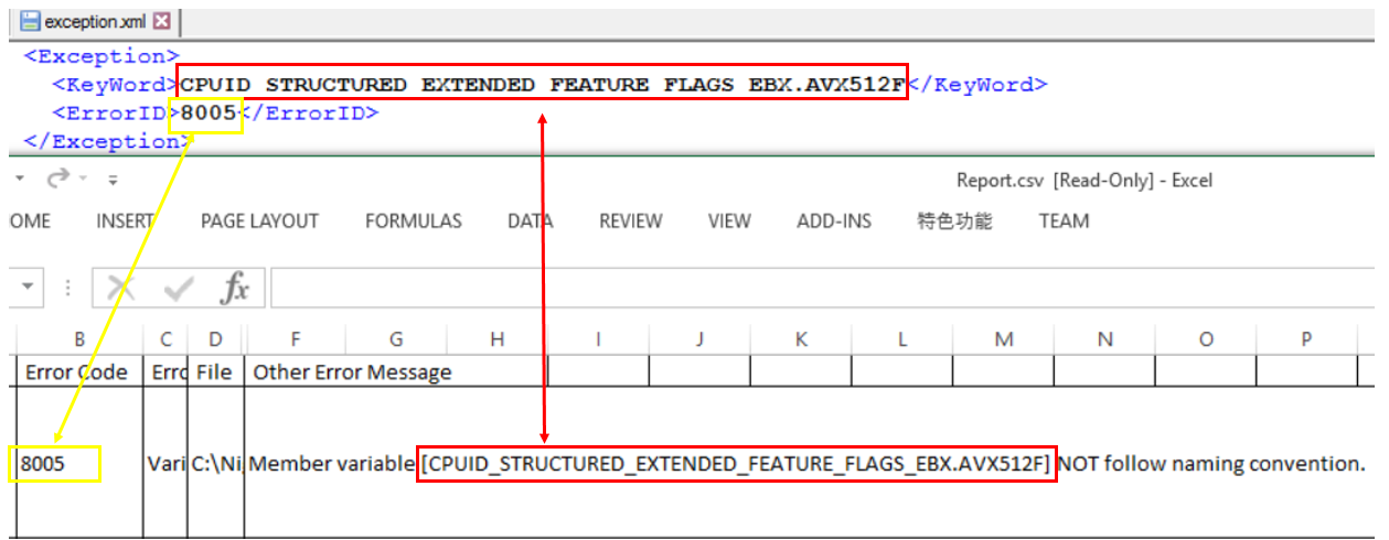
- b) If you want to skip a specific ECC error, you can add them to the exception.xml file.
The mapping relationship between exception format and ECC error is like below.
Tool Information
This is a table of all of the tools that are part of the EDK II BaseTools.
To build these tools see BuildTool Setup Guide.
| Tool Name | Tool Description |
|---|---|
| BootSectImage.exe | Parses the content of input file with Filename and prints BPB information to the screen. When patch option is specified it will patch BPB information using information from an input file or MBR. |
| BPDG.exe | Used to patch VPD binary data files. |
| build.exe | The master command line (CLI) tool that provides a single command for selecting various build options. |
| ECC.exe | Checks an EDK II Package directory for coding style. |
| EfiLdrImage.exe | Combines PE files into one with EFI loader header. |
| EfiRom.exe | Is used to build an Option ROM image from UEFI PE32 file(s) and/or legacy option ROM images that conform to PCI 2.3 or PCI 3.0 specifications for Option ROM layout. |
| GenBootSector.exe | Reads boot sector data of a drive into file or writes the boot sector data to a drive from a file. |
| GenCrc32.exe | Generates a CRC32 value when encoding the input file, then puts the calculated CRC32 value into the output file header. |
| GenDepex.exe | Parses the input dependency expression string or the preprocessed DSX file to generate the binary PI dependency expression according to module type. |
| GenFds.exe | Generates the Ffs, Fv, FD and Section data depending on the selected command line options. |
| GenFfs.exe | Generates FFS files for inclusion in a firmware volume. |
| GenFV.exe | Generates a PI firmware volume image or a UEFI capsule image from the PI firmware files or the binary files, which conforms to the firmware volume image format defined in PI specification or UEFI capsule image format defined in UEFI specification. |
| GenFw.exe | Processes a PE32 image to get image data or image file. |
| GenPage.exe | Is composed of two parts: the page table part, placed at the offset specified from option, and the non-page table part which is placed at the beginning of the output file. |
| GenPatchPcdTable.exe | Searches the image map file to find every patchable PCD name and its real address, then parses the binary EFI image to get each section name and address, and calculates PCD offset in the binary EFI image and writes it into the output file. |
| GenSec.exe | Generates valid EFI_SECTION type files, which conform to the firmware file section defined in the PI specification, from PE32/PE32+/COFF image files or other binary files. |
| GenVtf.exe | Generates the Boot Strap File (AKA Volume Top File, or VTF) for IPF images. |
| LzmaCompress.exe | Encodes or decodes files with LZMA encode or decode algorithm. |
| PatchPcdValue.exe | Sets the specific value into the binary image according to the input PCD offset and type. |
| Rsa2048Sha256GenerateKeys.exe | Generates signing keys. |
| Rsa2048Sha256Sign.exe | Used to sign an efi image |
| Split.exe | Creates two Binary files either in the same directory as the current working directory or in the specified directory. |
| TargetTool.exe | Prints current build setting, clear current setting, or modify the current setting in target.txt. |
| TianoCompress.exe | Encodes or decodes files with EFI extension encode or decode algorithm. |
| Trim.exe | Processes the preprocessed file by Compiler to remove the unused content to generate the file to be processed further by EDKII tools. |
| UPT.exe | Create, install or remove a UEFI Distribution Package. |
| VfrCompile.exe | Parses the preprocessed UEFI and Framework VFR file to generate UEFI IFR opcode table, Binary Data and IFR listing file. |
| VolInfo.exe | Displays the contents of a firmware volume residing in a file for informational purposes. |
EDK II Build Tools Project
This project is for development of the EDK II Build Tools. This is the primary set of tools for processing EDK II content. It contains configuration templates and source files. The tools support a Makefile based EDK II build with no additional packages required--the compiler tool chain, an assembler and optional ACPI assembler are the only additional tools need to build the EDK II project.
Source code in this project is divided into two types:
- Tools written in C (ANSI C) are primarily for tools that modify binary data structures
- Tools based on Python (Python) are primarily for tools that parse or process text files
Tools must adhere to the following requirements:
- Tools must be able to execute on a wide variety of operating systems.
- Tools written in Python use Python Tools and get converted to Win32 executable binary files before they are added to the BaseTools directory in the EDK II project.
To assist developers working with the Python tools, Python has been provided, along with the Python tools for creating graphical user interfaces (wxPython) and tools for creating native executable files (cxFreeze and py2app) for Microsoft*, Linux*, and Mac OS/X*. Python and the supporting Python package are available via SVN (See Resources below).
Tested and Released binaries for Microsoft Windows* 32-bit operating system are checked into the EDK II project along with the configuration files. The BaseTools use an INI format for build Meta Data files. You do not need to down load this project to build EDK II with the BaseTools. Refer to the BuildNotes2.txt file for details on using the BaseTools for the build.
Download and setup guide: BuildTool Setup Guide
- Prebuilt Windows tools are available at
https://github.com/tianocore/edk2-BaseTools-win32.git
- Note: the Prebuilt Windows tools (Win32 binaries) are only valid for the tip of https://github.com/tianocore/edk2. It is recommended to build the source tools for other EDK II branches and projects: Please see: Windows-systems#compile-tools
- BaseTools content (part of the edk2 project) is available at: https://github.com/tianocore/edk2.git
Project Info: Project Info ReadMe
Documentation User Manuals
View the EDK II Tools List for a description of each tool.
Releases
- Changes for UDK2017 BaseTools Notes
- Please see UDK2017 wiki page for more information on the latest release of Build Tools
UDK2015 :
Below Table are Releases for Archive purposes only
BuildTools Releases
Release: June 26, 2012
Downloads:
Description: Primary set of tools for processing EDK II content.
Tools included:
- BootSectImage
- Build Utility
- EfiLdrImage
- EfiRom
- Fpd2Dsc
- GenBootSector
- GenCrc32
- GenDepex
- GenFds
- GenFfs
- GenFv
- GenFw
- GenPage
- GenPatchPcdTable
- GenSec
- GenVtf
- UEFI Packaging Tool
- LzmaCompress
- Msa2Inf
- PatchPcdValue
- Spd2Dec
- SplitFile
- TargetTool
- TianoCompress
- Trim
- VfrCompiler
- VolInfo
Documents:
Readme:
General documentation:
Specifications: (None listed)
Technical information: (None listed)
Release: Jan 2, 2012
Downloads:
Description: Primary set of tools for processing EDK II content.
Documents:
Readme:
General documentation:
Specifications: (None listed)
Technical information: (None listed)
Notes
These tools are under constant development to ensure UEFI/PI specification conformance and to reduce build times.
Your Feedback is critical to making EDK II a success. Please submit any enhancements, defects, or requests through the edk2-devel mailing list.
Goto edk2-devel to Join the Mailing list
License information: BSD Plus Patent License
Project owner(s): See: Maintainers.txt
How to Build in edk2 with Stuart
EDK II packages are easy to build with set of tools called "stuart".
💡 If you are familiar with the
buildcommand and would like to learn aboutbuildvsstuart, see the comparison.
Steps are split into two categories: (1) one-time and (2) regular use.
One-Time Steps
If you've already completed these steps you don't need to run them again.
Pre-requisites (Git, Python, Compiler)
Git - Source Control Management (SCM) Tool
Git is the source control management tool used by this project.
You need git to pull the edk2 source code onto your system, make changes in the code, and submit
your changes back to the GitHub repository.
Python
Python is a programming language that many of the edk2 build tools are written in.
You will need Python to run the edk2 build tools including stuart, which is written in Python.
It is recommended you install a Python version that is equal to the version used in the
UsePythonVersion@0 step in this file
.azurepipelines/templates/pr-gate-steps.yml.
That version is constantly tested against the code in the repository.
C Compiler
A C compiler is needed to compile the firmware code.
Several options are available. This is an area where direct guidance cannot be provided.
You will need to choose a compiler supported on your host operating system and the particular firmware packages you are building.
However, it is common to use:
GCC on Linux
Ubuntu GCC Installation Instructions
apt-get update && apt-get install -y build-essential git nasm wget m4 bison flex uuid-dev python unzip acpica-tools gcc-multilib
Visual Studio on Windows
Visual Studio Installation Instructions (Windows)
  **Visual Studio 2022 Installation Instructions**
    ---

      Click to download [Visual Studio 2022 Build Tools](https://aka.ms/vs/17/release/vs_BuildTools.exe)


        Open an **Administrator Command Prompt** by right-clicking on **Command Prompt**
        and select **Run as Administrator**


        Change to the directory where you downloaded the `vs_BuildTools.exe` file
        (e.g. `C:\Downloads`)


        Enter the following command:

        `
          start /w vs_BuildTools.exe --quiet --wait --norestart --nocache --installPath C:\BuildTools ^
          --add Microsoft.VisualStudio.Component.VC.CoreBuildTools --add Microsoft.VisualStudio.Component.VC.Tools.x86.x64 ^
          --add Microsoft.VisualStudio.Component.Windows11SDK.22000 --add Microsoft.VisualStudio.Component.VC.Tools.ARM ^
          --add Microsoft.VisualStudio.Component.VC.Tools.ARM64
        `

    ---
**Visual Studio 2019 Installation Instructions**
  ---

    Click to download [Visual Studio 2019 Build Tools](https://aka.ms/vs/16/release/vs_BuildTools.exe)


      Open an **Administrator Command Prompt** by right-clicking on **Command Prompt**
      and select **Run as Administrator**


      Change to the directory where you downloaded the `vs_BuildTools.exe` file
      (e.g. `C:\Downloads`)


      Enter the following command:

      `
        start /w vs_BuildTools.exe --quiet --wait --norestart --nocache --installPath C:\BuildTools ^
        --add Microsoft.VisualStudio.Component.VC.CoreBuildTools --add Microsoft.VisualStudio.Component.VC.Tools.x86.x64 ^
        --add Microsoft.VisualStudio.Component.Windows10SDK.19041 --add Microsoft.VisualStudio.Component.VC.Tools.ARM ^
        --add Microsoft.VisualStudio.Component.VC.Tools.ARM64
      `

  ---
**Visual Studio 2017 Installation Instructions**
  ---

    Click to download [Visual Studio 2017 Build Tools](https://aka.ms/vs/15/release/vs_BuildTools.exe)


    Open an **Administrator Command Prompt** by right-clicking on **Command Prompt** and
    select **Run as Administrator**


    Change to the directory where you downloaded the `vs_BuildTools.exe` file
    (e.g. `C:\Downloads`)


      Enter the following command:

      `
        start /w vs_BuildTools.exe --quiet --wait --norestart --nocache --installPath C:\BuildTools ^
        --add Microsoft.VisualStudio.Component.VC.CoreBuildTools --add Microsoft.VisualStudio.Component.VC.Tools.x86.x64 ^
        --add Microsoft.VisualStudio.Component.Windows10SDK.17763 --add Microsoft.VisualStudio.Component.VC.Tools.ARM ^
        --add Microsoft.VisualStudio.Component.VC.Tools.ARM64
      `

  ---
Note: You can find the latest version of Visual Studio supported by edk2 on the
      [CI Status](https://github.com/tianocore/edk2#core-ci-build-status) section of the
      repo readme file.


      Note: If you still run into build problems finding tools in the SDK, try installing the Windows SDK manually
      using the following instructions.

  **Optional: Install the Windows SDK manually**
  ---

    Download the Windows Software Development Kit (SDK) from
    [Windows Dev Center - Windows SDK](https://developer.microsoft.com/en-us/windows/downloads/windows-sdk/)


    Follow the default options until you reach the "**Select the features you want to install**" page.

  Select the following options:
  Windows SDK Signing Tools for Desktop Apps
    Windows SDK for UWP Managed Apps
    Windows SDK for UWP C++ Apps
    Windows SDK for Desktop C++ x86 Apps
    Windows SDK for Desktop C++ amd64 Apps
    Windows SDK for Desktop C++ arm Apps
  Click **Download** and complete the installation process.

  ---
**Mono (Linux)**
[Mono](https://www.mono-project.com) needs to be installed on Linux.
`apt-get install mono-complete`
-
Clone the edk2 repo
- Open a command-prompt in the directory where you would like to keep the edk2 repo
- Clone the repo
- Example:
git clone https://github.com/tianocore/edk2.git
- Example:
-
Change into the edk2 directory
cd edk2
-
Create a Python virtual environment
- Note that the steps differ between Linux and Windows.
-
Linux Instructions
python3 -m venv .venvsource .venv/bin/activate- Windows Instructions
py -m venv .venv
.venv\Scripts\activate.bat4. Tell Git to ignore the Python virtual environment - Windows Instructions
-
Git will try to track your Python virtual environment as new code if it is not told to ignore it.
The edk2 project has been set to ignore the
.venvdirectory (since this commit), so if you are working on the current version of edk2 you can ignore this step.If you are working on another project (or older versions of the edk2 project), you can tell git to ignore the virtual environment like this:
- Open the file
.git/info/excludecd .gitcd info- Open the
excludefile in a text editor - Add the following line to the end of the file:
*venv*/**
- Close the file
- Note: Git will no longer try to track your Python virtual environments in this repository.
- Note that the steps differ between Linux and Windows.
That's it!
Your terminal may now indicate that a virtual environment is active by showing (.venv) before the
current line.
Regular Use Steps
These are steps you should run on a regular basis.
The steps are split into three categories: (1) once per session, (2) when dependencies are updated, and (3) before each build.
Once Per Session Steps
These assume your command prompt is in the edk2 repository directory.
-
Activate the Python virtual environment
- Linux
source .venv/bin/activate
- Windows
.venv\Scripts\activate.bat
- Linux
-
Update Python PIP modules
pip install -r pip-requirements.txt --upgrade
-
Get updated code dependencies
stuart_setup -c .pytool/CISettings.py
That's it!
When Dependencies are Updated Steps
The edk2 repo has a number of dependencies on external content. For example, it depends on git submodules, Python pip modules, tools in the form of application binaries, etc. If the corresponding version information for these is updated in the repo, you will need to pull the update.
The recommended steps to update dependencies are in this section.
Git Submodules
git submodule update --init --recursive
Python PIP Modules
pip install -r pip-requirements.txt --upgrade
Rebuild BaseTools
In Linux (Ubuntu) rebuilding BaseTools requires a one-time install of various dependencies, see the BaseTools build example.
Once any required dependencies are installed, the command to rebuild BaseTools (you may need to specify a different
toolchain with -t) is:
python3 BaseTools/Edk2ToolsBuild.py -t GCC5
Before Each Build Steps
Now every time you would like to build the code, you only need to run the following commands until you end this session and return.
-
Update other dependencies (like binaries)
-
stuart_update -c .pytool/CISettings.pyNote: It is recommended to specify the architecture and tool chain in the update command (see the
stuart_ci_buildcommand below) so any binaries specific to that architecture and tool chain are downloaded in this step.Note: The binaries downloaded by this step can be very large, it may take a long time to complete.
-
-
Run CI build (--help will give you options)
-
stuart_ci_build -c .pytool/CISettings.py TOOL_CHAIN_TAG=<your tag here>- Common options:
-p <pkg1,pkg2,pkg3>: To build only certain packages use a comma-separated list-a <arch1,arch2,arch3>: To run only certain architectures use a comma-separated list-t <target1,target2>: To run only tests related to certain targets use a comma-separated list
- Common options:
-
That's it to do a basic build.
The remainder of this page contains more details about the stuart_ci_build and stuart_build commands.
Examples
I want to build MdeModulePkg to test a change I made there
MdeModulePkg Build Example
The important parameter here is the -p parameter which specifies that MdeModulePkg should be built.
The example below uses:
- The
TOOL_CHAIN_TAGparameter to specify the build should useVS2019(Visual Studio 2019). - The
-aparameter is used to specify that theIA32andX64architectures should be built.
stuart_ci_build -c .pytool/CISettings.py -p MdeModulePkg -a IA32,X64 TOOL_CHAIN_TAG=VS2019
I only want to run the unit tests in a package
Unit Test Build Example
This example shows how to run only the host-based unit tests in MdeModulePkg.
- Normally, all package supported targets are tested including unit tests.
- Unit tests are run for the
NOOPTtarget.
stuart_ci_build -c .pytool/CISettings.py -p MdeModulePkg -a IA32,X64 TOOL_CHAIN_TAG=VS2019 -t NOOPT
The important parameter here is the -t parameter which specifies that only the NOOPT target should be built.
I want to build OvmfPkg to test a change I made there
OvmfPkg Build Example
OvmfPkg is considered a "platform firmware" for the QEMU open-source emulator.
- Therefore, it provides a platform build file (see What is PlatformBuild.py?)
- Located at OvmfPkg/PlatformCI/PlatformBuild.py
- Because we are building a platform build file, the build command will be
stuart_buildinstead ofstuart_ci_buildto compile the code
As a one-time step (and when binary dependencies are updated):
stuart_update -c PlatformBuild.py
Then to build:
stuart_build -c PlatformBuild.py -a IA32,X64 TOOL_CHAIN_TAG=VS2019
If you want to run CI checks such as CI plugins, you can use stuart_ci_build with the CI build file.
stuart_ci_build -c .pytool/CISettings.py -p OvmfPkg -a IA32,X64 TOOL_CHAIN_TAG=VS2019
I want to build OvmfPkg and automatically run with my firmware after build
OvmfPkg Build and Run Example
OvmfPkg is considered a "platform firmware" for the QEMU open-source emulator.
-
Therefore, it provides a platform build file (see What is PlatformBuild.py?)
-
Located at OvmfPkg/PlatformCI/PlatformBuild.py
-
Because we are building a platform build file, the build command will be
stuart_buildinstead ofstuart_ci_buildTo see what parameters are supported by this platform build file (at the time this page was written), we can pass the
--helpargument to thestuart_buildcommand:❯ stuart_build -c PlatformBuild.py --help usage: stuart_build [-h] [--SKIPBUILD] [--SKIPPREBUILD] [--SKIPPOSTBUILD] [--FLASHONLY] [--FLASHROM] [--UPDATECONF] [--CLEAN] [--CLEANONLY] [--OUTPUTCONFIG OUTPUTCONFIG] [-a BUILD_ARCH] [--build-config BUILD_CONFIG] [--verbose] options: -h, --help show this help message and exit --SKIPBUILD, --skipbuild, --SkipBuild Skip the build process --SKIPPREBUILD, --skipprebuild, --SkipPrebuild Skip prebuild process --SKIPPOSTBUILD, --skippostbuild, --SkipPostBuild Skip postbuild process --FLASHONLY, --flashonly, --FlashOnly Flash rom after build. --FLASHROM, --flashrom, --FlashRom Flash rom. Rom must be built previously. --UPDATECONF, --updateconf, --UpdateConf Update Conf. Builders Conf files will be replaced with latest template files --CLEAN, --clean, --CLEAN Clean. Remove all old build artifacts and intermediate files --CLEANONLY, --cleanonly, --CleanOnly Clean Only. Do clean operation and don't build just exit. --OUTPUTCONFIG OUTPUTCONFIG, --outputconfig OUTPUTCONFIG, --OutputConfig OUTPUTCONFIG Provide shell variables in a file -a BUILD_ARCH, --arch BUILD_ARCH Optional - CSV of architecture to build. IA32 will use IA32 for Pei & Dxe. X64 will use X64 for both PEI and DXE. IA32,X64 will use IA32 for PEI and X64 for DXE. default is IA32,X64 --build-config BUILD_CONFIG Provide shell variables in a file --verbose, --VERBOSE, -v verbose positional arguments: <key>=<value> - Set an env variable for the pre/post build process BLD_*_<key>=<value> - Set a build flag for all build types (key=value will get passed to build process) BLD_<TARGET>_<key>=<value> - Set a build flag for build type of <target> (key=value will get passed to build process for given build type)
The --flashonly and --flashrom commands are especially useful with OvmfPkg. They automatically load QEMU with the
newly built firmware.
The example below uses:
- The
TOOL_CHAIN_TAGparameter to specify that the build should useGCC5to build with GCC. - The
-aparameter is used to specify theIA32andX64architectures should be built. - The
--flashromparameter is used to load the firmware in QEMU and boot QEMU after the firmware build is completed.
stuart_build -c PlatformBuild.py -a IA32,X64 TOOL_CHAIN_TAG=GCC5 --flashrom
I want to build BaseTools
BaseTools Build Example
BaseTools has its own build script that leverages edk2-pytools to build the BaseTools applications.
Linux Pre-Requisites
-
sudo apt update -
sudo apt install build-essential uuid-devThe file BaseTools/Edk2ToolsBuild.py can be called as a standalone Python script. You just need to pass the tool chain tag you would like to build with.
Example:
python3 BaseTools/Edk2ToolsBuild.py -t GCC5
I just want to check if my changes will pass all the non-compiler checks in CI
CI Non-Compiler Checks Example
The NO-TARGET build target specifies that the actual firmware source code should not be built for any
particular target and, instead, the other parts of the CI process will be active such as the non-compiler checks
(plugins).
In the following example, the CI plugins will be run against all packages supported by the CISettings.py file.
stuart_ci_build -c .pytool/CISettings.py -t NO-TARGET
The CI checks could be run against a single package (or a selection of packages) by passing the package names to
with the -p parameter.
stuart_ci_build -c .pytool/CISettings.py -p MdePkg,UefiCpuPkg -t NO-TARGET
I want to fix all the spelling errors in my package. How do I just run the spell check plugin?
Spell Check Plugin Example
Plugins are automatically discovered in the workspace by stuart.
Stuart supports command-line arguments to disable all discovered plugins and only run those explicitly requested.
The following command disables all plugins and then enables only SpellCheck:
stuart_ci_build -c .pytool/CISettings.py --disable-all SpellCheck=run
Alternative Spell Check Plugin Example
You can also simply delete the other plugin directories so they are not discovered. You can then test with the remaining plugins and then use git to restore the deleted plugin directories back when done testing.
For example, to only test with the SpellCheck plugin, delete every other plugin folder from
.pytool/Plugin in your workspace.
Run the command to only perform CI checks:
stuart_ci_build -c .pytool/CISettings.py -t NO-TARGET
When done, restore the other plugin directories:
git restore .pytool/Plugin/**
Common Questions
What is CI?
Answer
Continuous integration is used in edk2 to test new contributions before they are merged to the edk2 main branch. Stuart is used within the edk2 CI process to pull build dependencies and build the code.
You can use stuart to perform the same CI checks locally that are done on the server (see the examples section).
Also see EDK II Continuous Integration.
What are BaseTools?
Answer
A collection of build related tools for edk2.
Examples:
- AutoGen
- Build
- GenSec
- GenFV
- GenFW
- GenRds
Each tool has a user manual located in BaseTools/UserManuals.
A more complete list of BaseTools is located in the EDK II Tools List.
What are edk2-pytools?
Answer
A collection of Python code for working with edk2.
- edk2-pytool-library - Python library code that seeks to provide an easy way to organize and share edk2 related functionality to facilitate reuse across environments, tools, and scripts.
- edk2-pytool-extensions - A Python project that consists of command line and other tools and extensions for building and maintaining an edk2 based UEFI firmware code tree.
What is CISettings.py?
Answer
CISettings.py is a common name given to a configuration file used with Stuart for CI. It is often
stored in a folder named .pytools in the root of a repository. So you'll likely encounter commands
like the following be used with the file:
stuart_ci_setup -c .pytool/CISettings.py TOOL_CHAIN_TAG=PUT_TAG_VALUE_HEREstuart_update -c .pytool/CISettings.py TOOL_CHAIN_TAG=PUT_TAG_VALUE_HEREstuart_ci_build -c .pytool/CISettings.py TOOL_CHAIN_TAG=PUT_TAG_VALUE_HERE
What is PlatformBuild.py?
Answer
PlatformBuild.py is a common name given to a configuration file used with Stuart for platform build.
It is often stored in the root directory of the package it builds.
For example:
stuart_setup -c SomePkg/PlatformBuild.py TOOL_CHAIN_TAG=PUT_TAG_VALUE_HEREstuart_update -c SomePkg/PlatformBuild.py TOOL_CHAIN_TAG=PUT_TAG_VALUE_HEREstuart_build -c SomePkg/PlatformBuild.py TOOL_CHAIN_TAG=PUT_TAG_VALUE_HERE
Like Stuart CI has "CI plugins", the build process has "build plugins". These can hook into the build in "pre-build" or "post-build".
What is the difference between stuart_ci_build and stuart_build?
Answer
stuart_ci_build- Runs CI plugins. By default, often runs CI on several packages at once. This includes all of the checks needed to consider the code ready for integration to the mainline.stuart_build- Does not run CI plugins. Builds one platform. Platforms often expose platform-specific parameters as defined in theirPlatformBuild.pyfile.
What does stuart_ci_build do exactly?
Answer
The Stuart CI process is composed of "CI plugins" that get discovered in the code tree at CI time and hook into the CI process. Some examples of CI plugins are a host-based unit test compile and execution, spell checking the code, performing markdown lint on the code, etc. Firmware (C code) compilation is performed during CI by a compiler CI plugin.
Each plugin reports back a pass/fail status. If any plugin fails, CI fails. However, plugins usually provide some
level of customization in a "CI package configuration file". If this file is present, it is in the root of the
package with the naming convention PkgName.ci.yaml. For example,
MdePkg.ci.yaml is the CI package configuration
file for MdePkg. Sometimes, CI plugins will allow the plugin to be set to run in "audit mode" so the plugin will run
and report results but not fail CI if errors are found. As an example, some packages in edk2 currently use this file to
run the spell checker CI plugin in audit mode.
The two main places to look for CI settings are:
- The CISettings.py file - Usually has repo-wide CI settings
- The CI package configuration file - Has package-specific CI settings for a given package
How do I get more detailed information if an error happens?
Answer
You can pass the -v argument to Stuart commands to get more detailed output.
Also, look in your /Build directory.
Each Stuart command produces a separate file. Open the file corresponding to the command you're using that has the failure.
stuart_ci_setup-CISETUP.txtstuart_setup-SETUPLOG.txtstuart_update-UPDATE_LOG.txtstuart_ci_build-CI_BUILDLOG.txtstuart_build-BUILDLOG_PACKAGENAME.txt
What are plugins?
Answer
The different types of plugins supported by Stuart and details about each type are available in the edk2-pytool-extensions Plugin Manager page.
How do I get lower-level technical details?
Answer
Start in the edk2-pytool-extensions User Documentation.
Multiple Workspace
Introduction
An update to the EDKII build tools now allows the setting of multiple paths that will be searched when attempting to resolve the location of packages. This new feature allows for more flexibility when designing a tree layout or combining sources from different sources. The new functionality is enabled through the addition of a new environment variable (PACKAGES_PATH).
The PACKAGES_PATH variable is an ordered list of additional search paths using the default path separator of the host OS between each entry. The first path in the list has the highest priority and the last path has the lowest priority. The path specified by the WORKSPACE variable always has the highest search priority over any PACKAGE_PATH entries.
To use this feature, the PACKAGES_PATH environment variable must be set prior to running the edksetup script. The reason for this is that the edksetup script determines the location of the Conf and BaseTools directory location based on the values of the WORKSPACE and PACKAGES_PATH environment variables.
The use of the PACKAGES_PATH environment variable is optional and if it is not defined the build will function like it has in the past.
Environment Variables
- WORKSPACE
- Location of the Build directory
- Always highest search priority
- PACKAGES_PATH
- List of additional paths to search for packages using OS path separator character
- Paths are listed in priority order
Example:
set WORKSPACE=c:\efi\test
set PACKAGES_PATH=%WORKSPACE%\platform;%WORKSPACE%\edk2
In this case WORKSPACE is the container for two trees as well as the location of the Build directory. The example assumes the set of code packages for a given platform are contained in the platform directory. While the code packages from the open source repository are contained in the edk2 directory.
When the build tools are run with this configuration the directories will be scanned in the following order to find packages listed in the DSC and FDF files.
- c:\efi\test
- c:\efi\test\platform
- c:\efi\test\edk2
Summary:
- Use of PACKAGES_PATH is not required
- PACKAGES_PATH must be set prior to running the edksetup script for correct tool configuration
ArmPkg Toolchain
List of ARM toolchains
| Toolchain Name | Host OS | Description |
|---|---|---|
| RVCT | Windows | Support RVCT3/4/5 versions |
| RVCTCYGWIN | Cygwin | Support RVCT3/4/5 versions |
| RVCTLINUX | Linux | Support RVCT3/4/5 versions |
| ARMGCC | Linux | Support Sourcery G++ Lite toolchain ARM EABI (tested: 2010q3) (arm-none-eabi- prefix) |
| ARMLINUXGCC | Linux | Support Linaro and ARM GNU/Linux toolchain (arm-linux-gnueabi- prefix) |
| XCODE32 | MacOS | Support XCode 3.2 |
ARM Toolchain supported in EDK2 BaseTools
Note: BaseTools does not need to by build when EDK2 is built from a MS Windows. Pre-built BaseTools binaries are provided by EDK2 repository.
Add Support for ARMGCC
1. Get the arm-none-eabi Toolchain from Code Sourcery:
wget http://www.codesourcery.com/sgpp/lite/arm/portal/package7813/public/arm-none-eabi/arm-2010.09-51-arm-none-eabi-i686-pc-linux-gnu.tar.bz2 tar xjf arm-2010.09-51-arm-none-eabi-i686-pc-linux-gnu.tar.bz2
2. Add the arm-none-eabi toolchain to your path
Add Support for ARMLINUXGCC
1. On a Ubuntu based-distribution, add the Linaro toolchain:
sudo add-apt-repository ppa:linaro-maintainers/toolchain
sudo apt-get update
sudo apt-get install gcc-arm-linux-gnueabi
ACPI Source Language (ASL) Compiler Setup
EDK II uses ACPI to describe platform configuration and power management methods to the operating system. These methods are described using ASL, which requires an additional compiler.
ACPI Component Architecture (ACPICA) Downloads
ASL 2.0 Introduction and Overview (whitepaper @ acpica.org)
Windows
Download and install the iasl compiler by downloading the Windows Binary Tools release package. Please check to see if your project requires a specific ACPICA tools version. Place the unzipped content ("iasl.exe") into the directory "C:\ASL" on your local hard drive (create the folder "C:\ASL" if it does not exist).
Linux
Install the iasl or acpica-tools package, depending on your Linux distribution. Example for Debian/Ubuntu:
bash$ sudo apt-get install iasl
GitHub Help
Note: New build instructions are available. It is recommended to start with the new instructions if learning how to
build edk2 for the first time. This page is retained for reference.
New instructions: Build Instructions
GitHub (https://help.github.com/index.html) provides step-by-step instructions for user registration and basic features supported by GitHub
- Setup GitHub for Linux | Windows | MAC | All (https://help.github.com/articles/set-up-git)
- To download and install a Git GUI interface (http://git-scm.com/)
GitHub EDK II Project Repositories
- The EDK II BaseTools are part of the EDK II project repository.
- The EDK II project repository is available at https://github.com/tianocore/edk2.
- Prebuilt Windows tools are available at https://github.com/tianocore/edk2-BaseTools-win32.
- Content that is not released under an accepted open source license can be found at https://github.com/tianocore/edk2-non-osi.
Getting the extra tools
Compiler
For both the BuildTools and EDK II projects, you will need to obtain a compiler from somewhere else. These instructions do not cover obtaining or installation of a compiler tools chain. The BaseTools build requires a C compiler; an assembler or ACPI assembler are not required to build tools in this project. BaseTools assume that a compiler is already configured in the environment.
Python
The BaseTools build supports the Makefile based build for EDK II. All Tools are written in either C or Python. The C tools must compile on all operating systems with various compilers, so the code is written using simple, standard functions and libraries. The Python-based tools are written assuming the features that were available in Python. GUI applications can be created in Python, using the wxPython package and all Python applications can be converted to run under a native OS (Windows, Linux or OS/X.) via the Python Tools.
The tools in this section are NOT required to build the EDK II project; they are needed to compile the BaseTools used to build the EDK II project.
- Linux and OS/X developers using a command line, create a directory
that will be used to hold the files, then change to that directory.
- Replace URL with apropriate one from Python Tools. Installation and configuration for these tools are left to the developer.
Refer to documentation in either the UserManuals or Source folders for more information.
- BuildTools User Manuals
How to Setup the EDK II Tree
See Getting Started with EDK II
EDK II Development Process
After setting up your build environment see EDK II Development Process for making contributions to the EDK II Project.
Further Help
If you have questions about the code or run into obstacles getting things to work for you, please join our edk2-devel email list and ask your EDK II related questions on the list.
Clang9 Tools Chain
New Cross OS tool chain CLANGPDB
CLANGPDB tool chain is added to directly generate PE/COFF image (EFI image). This tool chain uses LLVM clang C compiler and lld linker, generates PE/COFF image and PDB compatible debug symbol format. Now, it supports IA32/X64 Archs. It must use LLVM 9 or above release. LLVM 9 is ready on http://releases.llvm.org/download.html#9.0.0.
CLANGPDB is the cross OS tool chain. It can work on Windows/Linux/Mac. For the same source code, with the same version LLVM tool chain, CLANGPDB can generate the same binary image. So, the developer can choose the different development environment and work on the same code base. Besides, EDKII project build also requires third party tools: nasm and iasl. They both keep the same version. If so, the same binary image can be generated on this different OS.
LLVM tool chain provides the compiler and linker. To build EDK2 project, some other tools are still required. On Windows OS, nmake and Visual Studio are required to call Makefile and compile BaseTools C tools. On Linux/Mac, binutils and gcc are required to make and compile BaseTools C tools. Because VS or GCC are mainly used to compile BaseTools and provide nmake/make tool, they can keep on the stable version without update.
To build source code, CLANGPDB tool chain (-t CLANGPDB) can be specified on Windows OS, set CLANG_HOST_BIN=n, set CLANG_BIN=LLVM installed directory CLANG_HOST_BIN is used CLANG_HOST_PREFIX. Prefix n is for nmake. For example:
- set CLANG_HOST_BIN=n
- set CLANG_BIN=C:\Program Files\LLVM\bin\
- set IASL_PREFIX=C:\Asl\
On Linux/Mac, export CLANG_BIN=LLVM installed directory, CLANG_HOST_BIN is not required, because there is no prefix for make. For example:
- export CLANG_BIN=/home/CLANG9/bin/
Now, CLANGPDB tool chain has been verified in Edk2 packages and Ovmf/Emulator with LLVM 9.0.0 on Windows/Linux/Mac OS. OVMF IA32/IA32X64 all boots to Shell on Windows/Linux/Mac OS. Emulator can boot to Shell on Windows only with CLANGPDB. Emulator build with -DWIN_HOST_BUILD=TRUE -t CLANGPDB on Windows OS. OVMF IA32X64 RELEASE build generates the same BIOS images on Windows/Linux/Mac OS. OVMF X64 boot issue is tracked on https://github.com/tianocore/edk2/issues/8092
Cross OS/Host Reproducible Build
We enabled the reporducible build (https://reproducible-builds.org/) recently for edk2 MSVC and GCC/CLANG toolchains. And now we go further, CLANGPDB is the first Uefi toolchain to support "Cross OS/Host Reproducible Build", which is to generate exactly same firmware release binary across different operating systems. e.g. Linux, Windows. The magic behind it is the across OS llvm linker (lld). CLANGPDB is a perfect candidate for the Uefi defaut build toolchain in the future.
The "Cross OS/Host Reproducible Build" make the firmware binary to be real OS independent, which has several significant benefits for firmware:
- Cut the validation/testing effort for different OS built bianry.
- Easily to support customer and reproduce their build or runtime failures
- Harden identical build results for firmware in different OS and make the binary security to be OS independent.
To support "cross OS binary reproducible" feature, besides the above same version LLVM 9, please make sure to use the same version iasl compiler between different OS. E.g.
Linux:
~$ iasl -v
Intel ACPI Component Architecture
ASL+ Optimizing Compiler/Disassembler version 20180105
Copyright (c) 2000 - 2018 Intel Corporation
Windows:
>c:\ASL\iasl.exe -v
Intel ACPI Component Architecture
ASL+ Optimizing Compiler/Disassembler version 20180105
Copyright (c) 2000 - 2018 Intel Corporation
The verbos build and run steps in Linux
wget http://releases.llvm.org/9.0.0/clang+llvm-9.0.0-x86_64-linux-gnu-ubuntu-18.04.tar.xz
tar -xvf clang+llvm-9.0.0-x86_64-linux-gnu-ubuntu-18.04.tar.xz
sudo apt-get install build-essential git uuid-dev iasl nasm
git clone https://github.com/tianocore/edk2.git edk2
git submodule update --init
make -C BaseTools/
source edksetup.sh
export CLANG_BIN=~/Your/local/path/to/clang+llvm-9.0.0-x86_64-linux-gnu-ubuntu-18.04/bin/
build -p OvmfPkg/OvmfPkgIa32X64.dsc -a IA32 -a X64 -t CLANGPDB -b RELEASE
qemu-system-x86_64 -m 5120 -smp 1 -bios ~/your/local/path/to/edk2/Build/Ovmf3264/RELEASE_CLANGPDB/FV/OVMF.fd -global e1000.romfile=""  -machine q35 -serial mon:stdio -display none
The verbos build and run steps in Windows
Download the latest version Python from https://www.python.org/downloads/ and install it
Download http://releases.llvm.org/9.0.0/LLVM-9.0.0-win64.exe and install it
Download Visual Studio 2015 or 2017 or 2019 and install it, make sure nmake.exe, cl.exe, lib.exe and link.exe be ready.
Download nasm compiler http://www.nasm.us/, copy nasm.exe to C:\nasm\ directory.
Download iasl compiler https://acpica.org/downloads, copy iasl.exe to C:\ASL directory.
git clone https://github.com/tianocore/edk2.git edk2
git submodule update --init
edksetup.bat Reconfig
edksetup.bat Rebuild
set CLANG_HOST_BIN=n
set CLANG_BIN=C:\Program Files\LLVM\bin\
set IASL_PREFIX=C:\Asl\
build -p OvmfPkg\OvmfPkgIa32X64.dsc -a IA32 -a X64 -t CLANGPDB -b RELEASE
qemu-system-x86_64 -m 5120 -smp 1 -bios RootDirectory\edk2\Build\Ovmf3264\RELEASE_CLANGPDB\FV\OVMF.fd -global e1000.romfile=""  -machine q35 -serial mon:stdio -display none
Eclipse
Copyright (c) 2005, Intel Corporation All rights reserved.
Eclipse Public License - v 1.0
THE ACCOMPANYING PROGRAM IS PROVIDED UNDER THE TERMS OF THIS ECLIPSE PUBLIC LICENSE ("AGREEMENT"). ANY USE, REPRODUCTION OR DISTRIBUTION OF THE PROGRAM CONSTITUTES RECIPIENT'S ACCEPTANCE OF THIS AGREEMENT.
1. DEFINITIONS
"Contribution" means:
a) in the case of the initial Contributor, the initial code and documentation distributed under this Agreement, and b) in the case of each subsequent Contributor: i) changes to the Program, and ii) additions to the Program;
where such changes and/or additions to the Program originate from and are distributed by that particular Contributor. A Contribution 'originates' from a Contributor if it was added to the Program by such Contributor itself or anyone acting on such Contributor's behalf. Contributions do not include additions to the Program which: (i) are separate modules of software distributed in conjunction with the Program under their own license agreement, and (ii) are not derivative works of the Program.
"Contributor" means any person or entity that distributes the Program.
"Licensed Patents " mean patent claims licensable by a Contributor which are necessarily infringed by the use or sale of its Contribution alone or when combined with the Program.
"Program" means the Contributions distributed in accordance with this Agreement.
"Recipient" means anyone who receives the Program under this Agreement, including all Contributors.
2. GRANT OF RIGHTS
a) Subject to the terms of this Agreement, each Contributor hereby grants Recipient a non-exclusive, worldwide, royalty-free copyright license to reproduce, prepare derivative works of, publicly display, publicly perform, distribute and sublicense the Contribution of such Contributor, if any, and such derivative works, in source code and object code form.
b) Subject to the terms of this Agreement, each Contributor hereby grants Recipient a non-exclusive, worldwide, royalty-free patent license under Licensed Patents to make, use, sell, offer to sell, import and otherwise transfer the Contribution of such Contributor, if any, in source code and object code form. This patent license shall apply to the combination of the Contribution and the Program if, at the time the Contribution is added by the Contributor, such addition of the Contribution causes such combination to be covered by the Licensed Patents. The patent license shall not apply to any other combinations which include the Contribution. No hardware per se is licensed hereunder.
c) Recipient understands that although each Contributor grants the licenses to its Contributions set forth herein, no assurances are provided by any Contributor that the Program does not infringe the patent or other intellectual property rights of any other entity. Each Contributor disclaims any liability to Recipient for claims brought by any other entity based on infringement of intellectual property rights or otherwise. As a condition to exercising the rights and licenses granted hereunder, each Recipient hereby assumes sole responsibility to secure any other intellectual property rights needed, if any. For example, if a third party patent license is required to allow Recipient to distribute the Program, it is Recipient's responsibility to acquire that license before distributing the Program.
d) Each Contributor represents that to its knowledge it has sufficient copyright rights in its Contribution, if any, to grant the copyright license set forth in this Agreement.
3. REQUIREMENTS
A Contributor may choose to distribute the Program in object code form under its own license agreement, provided that:
a) it complies with the terms and conditions of this Agreement; and b) its license agreement: i) effectively disclaims on behalf of all Contributors all warranties and conditions, express and implied, including warranties or conditions of title and non-infringement, and implied warranties or conditions of merchantability and fitness for a particular purpose; ii) effectively excludes on behalf of all Contributors all liability for damages, including direct, indirect, special, incidental and consequential damages, such as lost profits; iii) states that any provisions which differ from this Agreement are offered by that Contributor alone and not by any other party; and iv) states that source code for the Program is available from such Contributor, and informs licensees how to obtain it in a reasonable manner on or through a medium customarily used for software exchange.
When the Program is made available in source code form:
a) it must be made available under this Agreement; and b) a copy of this Agreement must be included with each copy of the Program.
Contributors may not remove or alter any copyright notices contained within the Program.
Each Contributor must identify itself as the originator of its Contribution, if any, in a manner that reasonably allows subsequent Recipients to identify the originator of the Contribution.
4. COMMERCIAL DISTRIBUTION
Commercial distributors of software may accept certain responsibilities with respect to end users, business partners and the like. While this license is intended to facilitate the commercial use of the Program, the Contributor who includes the Program in a commercial product offering should do so in a manner which does not create potential liability for other Contributors. Therefore, if a Contributor includes the Program in a commercial product offering, such Contributor ("Commercial Contributor") hereby agrees to defend and indemnify every other Contributor ("Indemnified Contributor") against any losses, damages and costs (collectively "Losses") arising from claims, lawsuits and other legal actions brought by a third party against the Indemnified Contributor to the extent caused by the acts or omissions of such Commercial Contributor in connection with its distribution of the Program in a commercial product offering. The obligations in this section do not apply to any claims or Losses relating to any actual or alleged intellectual property infringement. In order to qualify, an Indemnified Contributor must: a) promptly notify the Commercial Contributor in writing of such claim, and b) allow the Commercial Contributor to control, and cooperate with the Commercial Contributor in, the defense and any related settlement negotiations. The Indemnified Contributor may participate in any such claim at its own expense.
For example, a Contributor might include the Program in a commercial product offering, Product X. That Contributor is then a Commercial Contributor. If that Commercial Contributor then makes performance claims, or offers warranties related to Product X, those performance claims and warranties are such Commercial Contributor's responsibility alone. Under this section, the Commercial Contributor would have to defend claims against the other Contributors related to those performance claims and warranties, and if a court requires any other Contributor to pay any damages as a result, the Commercial Contributor must pay those damages.
5. NO WARRANTY
EXCEPT AS EXPRESSLY SET FORTH IN THIS AGREEMENT, THE PROGRAM IS PROVIDED ON AN "AS IS" BASIS, WITHOUT WARRANTIES OR CONDITIONS OF ANY KIND, EITHER EXPRESS OR IMPLIED INCLUDING, WITHOUT LIMITATION, ANY WARRANTIES OR CONDITIONS OF TITLE, NON-INFRINGEMENT, MERCHANTABILITY OR FITNESS FOR A PARTICULAR PURPOSE. Each Recipient is solely responsible for determining the appropriateness of using and distributing the Program and assumes all risks associated with its exercise of rights under this Agreement , including but not limited to the risks and costs of program errors, compliance with applicable laws, damage to or loss of data, programs or equipment, and unavailability or interruption of operations.
6. DISCLAIMER OF LIABILITY
EXCEPT AS EXPRESSLY SET FORTH IN THIS AGREEMENT, NEITHER RECIPIENT NOR ANY CONTRIBUTORS SHALL HAVE ANY LIABILITY FOR ANY DIRECT, INDIRECT, INCIDENTAL, SPECIAL, EXEMPLARY, OR CONSEQUENTIAL DAMAGES (INCLUDING WITHOUT LIMITATION LOST PROFITS), HOWEVER CAUSED AND ON ANY THEORY OF LIABILITY, WHETHER IN CONTRACT, STRICT LIABILITY, OR TORT (INCLUDING NEGLIGENCE OR OTHERWISE) ARISING IN ANY WAY OUT OF THE USE OR DISTRIBUTION OF THE PROGRAM OR THE EXERCISE OF ANY RIGHTS GRANTED HEREUNDER, EVEN IF ADVISED OF THE POSSIBILITY OF SUCH DAMAGES.
7. GENERAL
If any provision of this Agreement is invalid or unenforceable under applicable law, it shall not affect the validity or enforceability of the remainder of the terms of this Agreement, and without further action by the parties hereto, such provision shall be reformed to the minimum extent necessary to make such provision valid and enforceable.
If Recipient institutes patent litigation against any entity (including a cross-claim or counterclaim in a lawsuit) alleging that the Program itself (excluding combinations of the Program with other software or hardware) infringes such Recipient's patent(s), then such Recipient's rights granted under Section 2(b) shall terminate as of the date such litigation is filed.
All Recipient's rights under this Agreement shall terminate if it fails to comply with any of the material terms or conditions of this Agreement and does not cure such failure in a reasonable period of time after becoming aware of such noncompliance. If all Recipient's rights under this Agreement terminate, Recipient agrees to cease use and distribution of the Program as soon as reasonably practicable. However, Recipient's obligations under this Agreement and any licenses granted by Recipient relating to the Program shall continue and survive.
Everyone is permitted to copy and distribute copies of this Agreement, but in order to avoid inconsistency the Agreement is copyrighted and may only be modified in the following manner. The Agreement Steward reserves the right to publish new versions (including revisions) of this Agreement from time to time. No one other than the Agreement Steward has the right to modify this Agreement. The Eclipse Foundation is the initial Agreement Steward. The Eclipse Foundation may assign the responsibility to serve as the Agreement Steward to a suitable separate entity. Each new version of the Agreement will be given a distinguishing version number. The Program (including Contributions) may always be distributed subject to the version of the Agreement under which it was received. In addition, after a new version of the Agreement is published, Contributor may elect to distribute the Program (including its Contributions) under the new version. Except as expressly stated in Sections 2(a) and 2(b) above, Recipient receives no rights or licenses to the intellectual property of any Contributor under this Agreement, whether expressly, by implication, estoppel or otherwise. All rights in the Program not expressly granted under this Agreement are reserved.
This Agreement is governed by the laws of the State of New York and the intellectual property laws of the United States of America. No party to this Agreement will bring a legal action under this Agreement more than one year after the cause of action arose. Each party waives its rights to a jury trial in any resulting litigation.
GCC Shell
Note: this package has been deprecated. Please refer to Shell and ShellPkg for the latest info.
Welcome to the gcc-shell project
The purpose of this project is to provide the ability to build the efi-shell project in the EDK II for the ARM processor type, and for all processor types with GCC. Currently you can build the efi-shell in the EDK II with the Edk Compatibility Package, but it does not support ARM or GCC. Since adding ARM and GCC support required modifying the efi-shell code in a way that is not compatible with the efi-shell project this new project was added.
The current gcc-shell project is based on the efi-shell project Subversion revision 34.
Short Lived Project
It is intended that this project will have a short life. The long term goal is to have a pure EDK II shell. When an EDK II shell is available this project will be retired.
Getting Started
This section assumes you have the edk2 checked out into the edk directory. Use Subversion to check out the GccShellPkg in the edk2 directory with the following commands:
cd edk2
svn co https://gcc-shell.svn.sourceforge.net/svnroot/gcc-shell/trunk/GccShellPkg  GccShellPkg
On Windows binary copies of the tools are checked into source control. On Unix like systems the tools must be built. So do the following to build the tools on a Unix like system. You should only need to do this one time after you checked the code out from source control:
~/work/edk2$ make -C BaseTools/Source/C
Follow the OS specific instructions to setup your build environment, and build a gcc compiler if needed. For Windows edksetup.bat, for Unix like systems you need to source edksetup.sh. Then you can build the shell from the edk2 directory. You only need to execute the edksetup script one time in you terminal window:
Windows with RVCT: Shell binary: edk2/Build/GccShellPkg/DEBUG_RVCT31/IA32/ShellFull.efi
C:\edk2> edksetup.bat
C:\edk2> build -p GccShellPkg/GccShellPkg.dsc -a ARM -t RVCT31
Windows Cygwin Bash shell with RVCT: Shell binary: edk2/Build/GccShellPkg/DEBUG_RVCT31CYGWIN/IA32/ShellFull.efi
~/work/edk2$  . edksetup.sh BaseTools
~/work/edk2$  build -p GccShellPkg/GccShellPkg.dsc -a ARM -t RVCT31CYGWIN
OS X with Xcode tools example: Shell binary: edk2/Build/GccShellPkg/DEBUG_XCODE32/IA32/ShellFull.efi
~/work/edk2$  . edksetup.sh BaseTools
~/work/edk2$  build -p GccShellPkg/GccShellPkg.dsc -a IA32 -t XCODE32
Linux with GCC tools example: Shell binary: edk2/Build/GccShellPkg/DEBUG_ELFGCC/X64/ShellFull.efi
~/work/edk2$  . edksetup.sh BaseTools
~/work/edk2$  build -p GccShellPkg/GccShellPkg.dsc -a X64 -t ELFGCC
Run gcc-shell in UnixPkg
cd edk2/UnixPkg
vi UnixPkg.fdf
Update the Flash Description File (.fdf) to point to the GccShellPkg binary we just built. Note path will change based on the compiler you used:
        SECTION PE32 = EdkShellBinPkg/FullShell/Ia32/Shell_Full.efi
#        SECTION PE32 =Build/GccShellPkg/DEBUG_XCODE32/IA32/ShellFull.efi
To:
#        SECTION PE32 = EdkShellBinPkg/FullShell/Ia32/Shell_Full.efi
        SECTION PE32 =Build/GccShellPkg/DEBUG_XCODE32/IA32/ShellFull.efi
Now build the UnixPkg to include the shell we can source level debug:
./build.sh
Run the UnixPkg emulator:
$ ./build.sh run
Building from: /Users/fish/work/Migration/edk2
using prebuilt tools
Reading symbols for shared libraries ...... done
Breakpoint 1 at 0xce84: file /Users/fish/work/Migration/edk2/UnixPkg/Sec/SecMain.c, line 1070.
(gdb)
Type r and hit return at the gdb prompt to start the emulator. Let the UnixPkg emulator run until it boots the EFI Shell (gcc-shell) and break into gdb with a ctrl-c. Your gdb back trace might vary, depending on where you broke in, but you should see symbols for the EFI-Shell. The current UnixPkg uses an EFI shell binary that was produced with Visual Studio so no symbols will be shown if you use that one.
^C
Program received signal SIGINT, Interrupt.
0x92423806 in __semwait_signal ()
(gdb) bt
#0  0x92423806 in __semwait_signal ()
#1  0x9244f441 in nanosleep$UNIX2003 ()
#2  0x0000b989 in msSleep (Milliseconds=0x14) at /Users/fish/work/Migration/edk2/UnixPkg/Sec/UnixThunk.c:102
#3  0x0000acf5 in UgaCheckKey (UgaIo=0x207880) at /Users/fish/work/Migration/edk2/UnixPkg/Sec/UgaX11.c:380
#4 0x0000d8b7 in _GasketUintn () at /Users/fish/work/Migration/edk2/Build/Unix/DEBUG_XCODE32/IA32/UnixPkg/Sec/SecMain/OUTPUT/Ia32/Gasket.iii:63 #5 0x0000d801 in GasketUgaCheckKey (UgaIo=0x207880) at /Users/fish/work/Migration/edk2/UnixPkg/Sec/Gasket.c:406 #6 0x454a25fb in UnixUgaSimpleTextInWaitForKey (Event=0x45603610, Context=0x45382110) at /Users/fish/work/Migration/edk2/UnixPkg/UnixUgaDxe/UnixUgaInput.c:169 #7 0x45faad3a in CoreDispatchEventNotifies (Priority=0x10) at /Users/fish/work/Migration/edk2/MdeModulePkg/Core/Dxe/Event/Event.c:185 #8 0x45faa639 in CoreRestoreTpl (NewTpl=0x4) at /Users/fish/work/Migration/edk2/MdeModulePkg/Core/Dxe/Event/Tpl.c:114 #9 0x45f9f197 in CoreReleaseLock (Lock=0x45fb1024) at /Users/fish/work/Migration/edk2/MdeModulePkg/Core/Dxe/Library/Library.c:102 #10 0x45faabd6 in CoreReleaseEventLock () at /Users/fish/work/Migration/edk2/MdeModulePkg/Core/Dxe/Event/Event.c:113 #11 0x45fab26c in CoreCheckEvent (UserEvent=0x45603210) at /Users/fish/work/Migration/edk2/MdeModulePkg/Core/Dxe/Event/Event.c:562 #12 0x45fab2db in CoreWaitForEvent (NumberOfEvents=0x1, UserEvents=0x45f94bc4, UserIndex=0x45f94bac) at /Users/fish/work/Migration/edk2/MdeModulePkg/Core/Dxe/Event/Event.c:621 #13 0x49bd2d45 in WaitForSingleEvent (Event=0x45603210, Timeout=0x0) at /Users/fish/work/Migration/edk2/GccShellPkg/Library/Event.c:212 #14 0x49be0442 in SEnvConIoRead (File=0x49c52a60, BufferSize=0x45f94d04, Buffer=0x49fe3010) at /Users/fish/work/Migration/edk2/GccShellPkg/shellenv/conio.c:553 #15 0x49bd490a in NShellPrompt (ImageHandle=0x49d95e10) at /Users/fish/work/Migration/edk2/GccShellPkg/newshell/init.c:949 #16 0x49bd4720 in InitializeShell (ImageHandle=0x49d95e10, SystemTable=0x45f73f90) at /Users/fish/work/Migration/edk2/GccShellPkg/newshell/init.c:715 #17 0x45f9e4e3 in CoreStartImage (ImageHandle=0x49d95e10, ExitDataSize=0x45f94eec, ExitData=0x45f94ee8) at /Users/fish/work/Migration/edk2/MdeModulePkg/Core/Dxe/Image/Image.c:1260 #18 0x4550cccc in BdsLibBootViaBootOption (Option=0x49ffa510, DevicePath=0x49ffa490, ExitDataSize=0x45f94eec, ExitData=0x45f94ee8) at /Users/fish/work/Migration/edk2/IntelFrameworkModulePkg/Library/GenericBdsLib/BdsBoot.c:382 #19 0x455252a9 in BdsBootDeviceSelect () at /Users/fish/work/Migration/edk2/IntelFrameworkModulePkg/Universal/BdsDxe/BdsEntry.c:214 #20 0x455255bc in BdsEntry (This=0x4552d01c) at /Users/fish/work/Migration/edk2/IntelFrameworkModulePkg/Universal/BdsDxe/BdsEntry.c:356 #21 0x45fad7e8 in DxeMain (HobStart=0x45f70010) at /Users/fish/work/Migration/edk2/MdeModulePkg/Core/Dxe/DxeMain/DxeMain.c:425 #22 0x45fadd1d in ProcessModuleEntryPointList (HobStart=0x42020000) at /Users/fish/work/Migration/edk2/Build/Unix/DEBUG_XCODE32/IA32/MdeModulePkg/Core/Dxe/DxeMain/DEBUG/AutoGen.c:287 #23 0x45f97773 in _ModuleEntryPoint (HobStart=0x42020000) at /Users/fish/work/Migration/edk2/MdePkg/Library/DxeCoreEntryPoint/DxeCoreEntryPoint.c:54 (gdb)
You can see by calls to InitializeShell() and NShellPrompt() that the shell supports source level debugging.
The UnixPkg should produce an X11 window that is the emulated EFI graphics console containing a shell prompt. Do the ctrl-c after you see the shell prompt
Common Errors
 build.py...
 : error 1005: There are 2 INF files in /Users/fish/work/edk2/GccShellPkg.
    Please use '-m <INF_FILE_PATH>' switch to choose one.
If you build from the edk2/GccShellPkg directory you need to pick either Shell.inf or ShellFull.inf. If you cd up to the edk2 directory this build error will go away and both .inf files will be built.
 'c:/Program' is not recognized as an internal or external command,
 operable program or batch file.
 NMAKE : fatal error U1077: '"c:/Program Files/ARM/RVCT/Programs/3.1/761/win_32-pentium/armcc"' : return code '0x1'
The default location of the RVCT compiler is not correct. Edit edk2/Conf/tools_def.txt and update the line that starts with DEFINE RVCT31_TOOLS_PATH to match the location of your RVCT install.
Building ... /cygdrive/c/work/edk2/MdePkg/Library/BasePcdLibNull/BasePcdLibNull.inf [ARM]
"/cygdrive/c/work/edk2/BaseTools/Bin/CYGWIN_NT-5.1-i686/armcc_wrapper.py" "/cygdrive/c/Program Files/ARM/RVCT/Programs/3.1/761/win_32-pentium/armcc" --cpu Cortex-A8 --c90 -c -g -O2 --no_autoinline --asm --gnu --apcs /interwork --signed_chars --no_unaligned_access --split_sections --preinclude AutoGen.h --diag_warning 167 -o /cygdrive/c/work/edk2/Build/BeagleBoard/DEBUG_RVCT31CYGWIN/ARM/MdePkg/Library/BasePcdLibNull/BasePcdLibNull/OUTPUT/./PcdLib.obj -I/cygdrive /c/work/edk2/MdePkg/Library/BasePcdLibNull -I/cygdrive/c/work/edk2/Build/BeagleBoard/DEBUG_RVCT31CYGWIN/ARM/MdePkg/Library/BasePcdLibNull/BasePcdLibNull/DEBUG -I/cygdrive/c/work/edk2/MdePkg -I/cygdrive/c/work/edk2/MdePkg/Include -I/cygdrive /c/work/edk2/MdePkg/Include/Arm /cygdrive/c/work/edk2/MdePkg/Library/BasePcdLibNull/PcdLib.c /bin/sh: /cygdrive/c/Program Files/ARM/RVCT/Programs/3.1/761/win_32-pentium/armcc: No such file or directory
The default location of the RVCT compiler is not correct. Edit edk2/Conf/tools_def.txt and update the line that starts with DEFINE RVCT31CYGWIN_TOOLS_PATH to match the location of your RVCT install.
edk2/Conf/tools_def.txt file does not exist
This file is not checked into source control. When you setup your build environment the first time edk2/BaseTools/Conf/tools_def.template gets copied to edk2/Conf/tools_def.txt. This allows you to make local modification to match the locations of the compilers installed on your system without having to check that back into source control. If edk/Conf/tools_def.txt exists it will not get overwritten. So you should only have to change it one time.
GenSec: ERROR 0001: Error opening file
  /Users/fish/work/edk2/Build/GccShellPkg/DEBUG_XCODE32/IA32/ShellFull.efi
GenSec: ERROR 2000: Status is not successful
  Status value is 0x2
You forgot to build the GccShellPkg. Follow the instructions in Getting Started to build the GccShellPkg. You do not need to checkout the GccShellPkg from subversion again if you have already done it once.
Install Some External Tools
Getting and Installing the Required Tools for Building EDK II.
Note: The step-by-step instructions also cover installing pre-requisite build tools for some build environments.
Requirements
- An IA32 or X64 based development workstation (IPF workstations are not supported)
- Microsoft Windows XP or Vista, Apple Mac OS/X (10.4 or later) or Linux operating system
- Disk space for compiler tools
- Minimum of 1GB of disk space for edk2 development tree and output files
- Minimum of 512MB (1GB recommended) of system memory
The one of the following is required to be able to obtain the EDK II.
| Name | URL |
|---|---|
| TortoiseSVN | http://tortoisesvn.net/downloads |
| Command Line Tool | http://subversion.apache.org/packages.html |
Third Party Tools
3rdParty Tools must include: a C pre-processor, C compiler, static linker, dynamic linker, and an assembler and assembly linker. For creating ACPI tables required by platforms, an ACPI assembler is also required.
The compiler tool chains are not provided as part of EDK II. Before purchasing a compiler tool chain, make sure to review the End User License Agreement (EULA) that comes with the software to ensure that creating EFI firmware and applications (for commercial purposes) for the target architecture is permitted.
At least one of the following 3rd party compiler tool chain is required:
| Name | Version | URL | Note |
|---|---|---|---|
| Cygwin | 4.1.2 | http://www.cygwin.com | Instructions for installation of GCC are included in the BaseTools\gcc directory. |
| Microsoft Visual Studio | 2005 Professional | http://msdn2.microsoft.com/en-us/vstudio | The default tool chain for the IA32 and X64 builds. |
| Microsoft Visual Studio | 2005 Team Suite | http://msdn2.microsoft.com/en-us/vstudio | Needed for building IPF targets if the DDK is not installed. |
| Microsoft Visual Studio | 2003 .NET | http://msdn2.microsoft.com/en-us/vstudio | May only be available through a MSDN subscription. If the DDK is not available, MASM 6.15 can be used for the assembler. |
| Intel C++ Compiler for Windows | 9.1 | http://www.intel.com | The Intel Compiler requires a Microsoft Visual Studio installation. |
| Intel C Compiler for EFI Byte Code | 1.2 | http://www.intel.com/cd/software/products/asmo-na/eng/compilers/efibc/index.htm | |
| Microsoft Windows Driver Development Kit6 (DDK) | 3790.1830 | The default tool chain for IPF builds. To download and use the DDK, you must burn the ISO file to a CD or DVD. | |
| Windows Server 2003 SP1 DDK | |||
| Microsoft ACPI Source Language Assembler | 3.0.0NT or later | http://www.microsoft.com/whdc/system/pnppwr/powermgmt/default.mspx | |
| Intel ACPI Component Architecture | 20060113 or later |-http://www.intel.com/technology/iapc/acpi/downloads.htm |
Windows XP or Windows Vista
After installing the compiler tools and your Subversion client, download the edk2, read the BuildNotes2.txt file and you will be ready to build an image.
All builds are started from a command prompt window.
Cygwin
If you install cygwin (for GCC support under Windows) you should install it in "Unix" mode. The gcc tool chain will not compile in "DOS" mode.
For Cygwin, you may also find the Unix-like systems step-by-step instructions valuable.
Environment Variables
Environment variables are case sensitive. You must use the exact case as in the examples of this document. Even though windows does not care about case, other operating systems that are supported do care about case.
You need to set WORKSPACE to the location of the edk2 directory that you pulled from Subversion. For example:
set WORKSPACE=c:\workspace\edk2
It is recommended that you wrap up all the environment variables above into a script that you can launch each time you begin to do development in your EDK II workspace.
Multiple Workspaces are also supported see how: Multiple_Workspace
First Build
The step-by-step documents how to build the MdeModulePkg under various environments.
Nasm
Download Nasm
The NASM assembler is available from: http://www.nasm.us/
The link to the release notes for what is new in NASM 2.15.05 is at: http://www.nasm.us/doc/nasmdocc.html
- NASM 2.12 adds support for Codeview version 8 (cv8) which allows for source level debug of NASM sources when EDK II sources are built using Microsoft Visual Studio* 20xx tool chains
- NASM 2.15.05 increases CPU instruction mnemonic support and adds options for deterministic builds.
NASM 2.15.05 is the recommended minimum version.
Nasm Prefix
Nasm environment variable is used for the EDK II Build If assembly code is used by the modules and the NASM assembler is used, the system environment variable, NASM_PREFIX must be set as shown below and must include the trailing backslash character:
C:\edk2> set NASM_PREFIX=C:\nasm\
Unix Like Systems
Note: New build instructions are available. It is recommended to start with the new instructions if learning how to
build edk2 for the first time. This page is retained for reference.
New instructions: Build Instructions
This page provides step-by-step instructions for setting up a EDK II build environment on various Unix-like systems.
These instructions are not recommended for most EDK II developers. If you are working with a supported Linux distribution, then the Using EDK II with Native GCC instructions are faster, easier, and produce a smaller UEFI binary image.
Getting started for UNIX-like operating systems
These instructions will be written as a series of commands executed from a command terminal.
Often these instructions will contain a command which needs to be executed in the terminal window. For example:
bash$ echo this bold text is a sample command
To execute this command, highlight the bold text of the command in your web browser. Most web browsers should be able to copy the text by selecting Copy under the Edit menu. Now, change back to the terminal application, and there should be a Paste operation under the Edit menu. After pasting the command into the shell, you may need to press the enter or return key to execute the command.
Of course, there may be other ways to copy and paste the command into the terminal which are specific to the windowing environment and applications that you are using. If all else fails, however, you can type the command by hand.
Some commands are very long, and we use the backslash character (\ to tell the shell program that the command is not finished. For example:
bash$ echo this bold text is a sample command \
        which is broken into two lines
When you copy and paste, make sure you include all lines of the command (including the backslash (\ characters). If you are typing the command, you can remove the backslash character (\ and combine the lines into a single line if you prefer.
If a command starts with the sudo command, then you may be prompted for your user password. This will be the same password as you used to login to the system.
For the purposes of this set of instructions, we will be using the following paths.
| Edk2 source tree: | ~/src/edk2 |
| GCC X64 cross-compiler installation: | ~/programs/gcc/x64 |
| GCC IA32 cross-compiler installation: | ~/programs/gcc/ia32 |
| Intel ASL Compiler installation: | ~/src/acpica-unix-20090521/compiler/iasl (symlink to compiler at ~/programs/iasl) |
You will need to change the commands if you want to use different locations, but this is not recommended unless you are sure that you know what you are doing.
Internet proxies
If your network utilizes a firewall with a web proxy, then you may need to configure your proxy information for various command line applications to work. You may need to consult with your network administrator to find out the computer name and port to use for proxy setup. The following commands are common examples of how you would configure your proxy by setting an environment variable:
bash$ export http_proxy=http://proxy.domain.com:proxy_port
bash$ export ftp_proxy=$http_proxy
To utilize the subversion source control command behind an internet firewall with a web proxy, you should configure the ~/.subversion/servers file.
Cygwin 1.7.1
Notes:
- Cygwin is not officially supported or tested by the edk2 project at this time.
- Building of EDK II components will be done using bash.
Prerequisites:
- Cygwin 1.7.1 is currently installed on the system.
- Cygwin 1.7.1 setup.exe is available on the system to install additional packages as needed.
Run Cygwin setup.exe and install the following additional packages.
- bison
- flex
- libgmp-devel
- libiconv
- libmpfr-devel
- gcc (use the compiler upgrade helper option under Devel)
- make
- python
- subversion
- wget
- libuuid-devel
- util-linux (for uuidgen)
When pulling source files using subversion you may choose to get them to a more Windows friendly location. All system drives are mapped under /cygdrive when using CYGWIN and bash (ie. C:\ maps to /cygdrive/c). This allows you to substitute ~/src/edk2 for an alternate path such as /cygdrive/c/src/edk2 so files can be access at C:\src\edk2 as well.
Continue with common instructions for Unix
The remaining instructions are common for most UNIX-like systems.
Fedora 11
- Fedora 11 is not officially supported or tested by the edk2 project at this time.
- These instructions assume that the Software Development option was enabled during the Fedora installation.
Open the GNOME Terminal program
These instructions will utilize Fedora's built in command shell (bash) via the GNOME Terminal application. To open the Terminal application, locate it under the Applications menu and the System Tools sub-menu.
Install MPFR library
The MPFR library must be installed to allow the gcc cross compiler to be built.
bash$ mkdir ~/src
bash$ cd ~/src
bash$ wget http://www.mpfr.org/mpfr-current/mpfr-2.4.1.tar.bz2
bash$ tar -jxf mpfr-2.4.1.tar.bz2
bash$ cd mpfr-2.4.1
bash$ ./configure --prefix=/usr
bash$ make
To install the library, you must be root. Therefore we use 'su' to become the root user, for the 'make install' command.
bash$ su
bash$ make install
bash$ exit
Continue with common instructions for Unix
The remaining instructions are common for most UNIX-like systems.
Mac OS X 10.5
Xcode Tools
The first step is to install the Apple Xcode development environment:
``http://developer.apple.com/tools/xcode
To install Xcode, you must register as an Apple developer, and download the Xcode installation disk image (which is fairly large). These instructions were verified with Xcode 3.0. Within the Xcode Tools disk image, only the Xcode Tools.mpkg package needs to be installed.
Open OS X Terminal program
Past this point, the remaining instructions will utilize OS X's built in command shell (bash) via the Terminal application. To open the command terminal application, open Finder, then press the Cmd-Shift-U key combination. (This opens the Applications => Utilities folder.) In the Utilities folder, you should see the Terminal application.
GMP & MPFR (if behind a web proxy)
The gmp and mpfr libraries are needed to build the gcc cross compiler at a later point in these instructions. Building these libraries on OS X can present some difficulties, so if you are not behind a network firewall, then consider using the macports project to install these libraries. (see below) Be sure to set the http_proxy and ftp_proxy environment variables before using the 'curl' commands below.
bash$ mkdir ~/src
bash$ cd ~/src
bash$ curl --remote-name \
  ftp://ftp.gnu.org/gnu/gmp/gmp-4.2.2.tar.bz2
bash$ tar jxvf gmp-4.2.2.tar.bz2
bash$ cd gmp-4.2.2
bash$ ./configure --prefix=/usr
bash$ make
bash$ make check
bash$ sudo make install
Note: This might be needed for 64-bit machines if the MPFR configure fails below.
bash$ export CFLAGS="-m64"

bash$ cd ~/src
bash$ curl --remote-name \
  http://www.mpfr.org/mpfr-current/mpfr-2.4.1.tar.bz2
bash$ tar -jxf mpfr-2.4.1.tar.bz2
bash$ cd mpfr-2.4.1
bash$ ./configure --prefix=/usr
bash$ make
bash$ sudo make install
GMP & MPFR via Macports (if not behind web proxy)
If you are not behind a network firewall, then the http://www.macports.org project can greatly simlify the installation of gmp & mpfr. (Macports does not work easily with web proxies at this time.) After installing macports you should be able to simply run this command at the shell prompt.
bash$ sudo port install gmp mpfr
Continue with common instructions for Unix
The remaining instructions are common for most UNIX-like systems.
Ubuntu 9.10
Note: The Ubuntu platform is not officially supported or tested by the edk2 project at this time.
Open the GNOME Terminal program
These instructions will utilize Ubuntu's built in command shell (bash) via the GNOME Terminal application. To open the Terminal application, locate it under the Applications menu and the Accessories sub-menu.
Install required software from apt
Several ubuntu packages will be needed to fully set up an edk2 build environment. In order to easily install all the requirements, you need to run this command.
bash$ sudo apt-get install build-essential uuid-dev texinfo \
        bison flex libgmp3-dev libmpfr-dev subversion
Continue with common instructions for Unix
The remaining instructions are common for most UNIX-like systems.
Using EDK II With Native GCC
New build instructions are available. It is recommended to start with the new instructions if learning how to build edk2 for the first time. This page is retained for reference.
New instructions: Build Instructions
This page provides step-by-step instructions for setting up a EDK II build environment on Linux using a native GCC installation (4.4+). This EDK II setup does not require the Mingw version of GCC to be built, and therefore can be much faster to setup.
Getting Started
These instructions will be written as a series of commands executed from a command terminal.Often these instructions will contain a command which needs to be executed in the terminal window. For example:
bash$ echo this text is a sample command
To execute this command, highlight the text of the command in your web browser. (Note that the 'bash$' text is not part of the command!) Most web browsers should be able to copy the text by selecting Copy under the Edit menu. Now, change back to the terminal application, and there should be a Paste operation under the Edit menu. After pasting the command into the shell, you may need to press the enter or return key to execute the command.
Of course, there may be other ways to copy and paste the command into the terminal which are specific to the windowing environment and applications that you are using. If all else fails, however, you can type the command by hand.
Some commands are very long, and we use the backslash character (\) to tell the shell program that the command is not finished. For example:
bash$ echo this bold text is a sample command \
        which is broken into two lines
When you copy and paste, make sure you include all lines of the command (including the backslash (\) characters). If you are typing the command, you can remove the backslash character (\) and combine the lines into a single line if you prefer.
If a command starts with the sudo command, then you may be prompted for your user password. This will be the same password as you used to login to the system.
For the purposes of this set of instructions, we will be using the following paths.
| Edk2 source tree: | $HOME/src/edk2 |
| Native GCC 4.x compiler installation: | /usr/bin/gcc |
| Intel ASL Compiler installation: | /usr/bin/iasl |
You will need to change the commands if you want to use different locations, but this is not recommended unless you are sure that you know what you are doing.
Internet proxies
If your network utilizes a firewall with a web proxy, then you may need to configure your proxy information for various command line applications to work. You may need to consult with your network administrator to find out the computer name and port to use for proxy setup. The following commands are common examples of how you would configure your proxy by setting an environment variable:
bash$ export http_proxy=http://proxy.domain.com:proxy_port
bash$ export ftp_proxy=$http_proxy
To utilize the subversion source control command behind an internet firewall with a web proxy, you should configure the ~/.subversion/servers file.
Ubuntu 20.04 LTS
Note: These instructions utilize GCC5 & NASM compiler support (added in early 2016), along with git (replaces subversion). GCC 4.x is still supported. GCC5 is not mandatory.
Open the GNOME Terminal program
These instructions will utilize Ubuntu's built in command shell (bash) via the GNOME Terminal application. To open the Terminal application, locate it under the Applications menu and the Accessories sub-menu.
Install required software from apt
Several Ubuntu packages will be needed to set up the build environment for EDK II. The following command will install all required packages:
bash$ sudo apt install build-essential uuid-dev iasl git nasm python-is-python3
build-essential - Informational list of build-essential packages
uuid-dev - Universally Unique ID library (headers and static libraries)
iasl - Intel ASL compiler/decompiler (also provided by acpica-tools)
git - support for git revision control system
nasm - General-purpose x86 assembler
python-is-python3 - Ubuntu 20.04 python command is 'python3' but edk2
tools use 'python'
Continue with common instructions
The remaining instructions are common for most UNIX-like systems.
Ubuntu 16.04 LTS / Ubuntu 16.10
Note: These instructions utilize GCC5 & NASM compiler support (added in early 2016), along with git (replaces subversion). GCC 4.x is still supported. GCC5 is not mandatory.
Open the GNOME Terminal program
These instructions will utilize Ubuntu's built in command shell (bash) via the GNOME Terminal application. To open the Terminal application, locate it under the Applications menu and the Accessories sub-menu.
Install required software from apt
Several Ubuntu packages will be needed to set up the build environment for EDK II. The following command will install all required packages:
bash$ sudo apt-get install build-essential uuid-dev iasl git gcc-5 nasm python3-distutils
build-essential - Informational list of build-essential packages
uuid-dev - Universally Unique ID library (headers and static libraries)
iasl - Intel ASL compiler/decompiler (also provided by acpica-tools)
git - support for git revision control system
gcc-5 - GNU C compiler (v5.4.0 as of Ubuntu 16.04 LTS)
nasm - General-purpose x86 assembler
python3-distutils - distutils module from the Python standard library
Continue with common instructions
The remaining instructions are common for most UNIX-like systems.
Instructions for older Linux Environments
Note: the instructions below have not been updated for compilers newer than GCC 4.4, git (replaces subversion) or NASM. Newer builds may fail without satisfying these dependecies. We recommend moving to newer Linux distributions unless you have a dependency on a specific version.
Note: Limitations of GCC 4.4
Note: The GCC 4.4 toolchain only supports building images for the IA32 and X64 architectures. We recommend using newer toolchains.
Also, in some cases if GCC 4.4 is installed under Linux x86 (32-bit mode), then it may only support building UEFI images for the IA32 architecture.
Arch Linux 2010.05
Note: Arch Linux is not officially supported or tested by the edk2 project at this time.
Open the GNOME Terminal program
These instructions will utilize Arch Linux's built in command shell (bash) via the GNOME Terminal application. To open the Terminal application, locate it under the Applications menu and the System Tools sub-menu.
Install required software with pacman
To install the required packages, you must be root. Therefore we use 'su' to become the root user.
bash$ su -
bash$ pacman -S base-devel glibc iasl python2 subversion
bash$ exit
Continue with common instructions
The remaining instructions are common for most UNIX-like systems.
Fedora 13
Note: Fedora is not officially supported or tested by the edk2 project at this time.
Note: x86 (32-bit) Fedora will install GCC 4.4 which is only capable of building UEFI for the IA32 architecture.
Open the GNOME Terminal program
These instructions will utilize Fedora's built in command shell (bash) via the GNOME Terminal application. To open the Terminal application, locate it under the Applications menu and the System Tools sub-menu.
Install required software with yum
To install the required packages, you must be root. Therefore we use 'su' to become the root user.
bash$ su -
bash$ yum groupinstall development-tools
bash$ yum install iasl libuuid-devel
bash$ exit
Continue with common instructions
The remaining instructions are common for most UNIX-like systems.
Mandriva 2010
Note: Mandriva is not officially supported or tested by the edk2 project at this time.
Note: x86 (32-bit) Mandriva will install GCC 4.4 which is only capable of building UEFI for the IA32 architecture.
Open the Terminal program
These instructions will utilize Mandriva's built in command shell (bash) via the Terminal application. To open the Terminal application, locate it under the Applications menu and the Tools sub-menu.
Install required software with urpmi
To install the required packages, you must be root. Therefore we use 'su' to become the root user.
bash$ su -
bash$ urpmi task-c++-devel iasl libuuid-devel subversion
bash$ exit
Continue with common instructions
The remaining instructions are common for most UNIX-like systems.
openSUSE 12.1
Note: openSUSE is not officially supported or tested by the edk2 project at this time.
Open the GNOME Terminal program
These instructions will utilize openSUSE's built in command shell (bash) via the GNOME Terminal application. To open the Terminal application, click the 'Computer' menu, click the 'More Applications' button, and then enter 'terminal' into the filter text box.
Install required software with zypper
Several openSUSE packages will be needed to fully set up an edk2 build environment. In order to easily install all the requirements, you need to run this command.
bash$ sudo zypper in -t pattern devel_basis
Continue with common instructions
The remaining instructions are common for most UNIX-like systems.
Ubuntu 10.10
Notes:
- The Ubuntu platform is not officially supported or tested by the edk2 project at this time.
- Both the x86 (32-bit) and x86-64 (64-bit) Ubuntu versions will install GCC 4.4 which is capable of building UEFI for both the IA32 and X64 architectures.
- These instructions should work for Ubuntu 10.04 as well
Open the GNOME Terminal program
These instructions will utilize Ubuntu's built in command shell (bash) via the GNOME Terminal application. To open the Terminal application, locate it under the Applications menu and the Accessories sub-menu.
Install required software from apt
Several ubuntu packages will be needed to fully set up an edk2 build environment. In order to easily install all the requirements, you need to run this command.
bash$ sudo apt-get install build-essential subversion uuid-dev iasl
Continue with common instructions
The remaining instructions are common for most UNIX-like systems.
See Also
- Unix-like systems - Instructions which walk through building the Mingw GCC cross-compiler
Windows Systems Toolchain Matrix
Change TOOL_CHAIN_TAG in the file Conf\Target.txt for Windows Visual Studio Versions according to the following Matrix
| Visual Studio | V. Version | WinXP / Win7 /IA32 | Win7 / Win8x / Win10 x64 |
|---|---|---|---|
| VS2005 | 8 | VS2005 | VS2005x86 |
| VS2008 | 9 | VS2008 | VS2008x86 |
| VS2010 | 10 | VS2010 | VS2010x86 |
| VS2012** | 11 | VS2012 | VS2012x86 |
| VS2013** | 12 | VS2013 | VS2013x86 |
| Below Recommended | |||
| VS2015*** | 14 | VS2015 | VS2015x86 |
| VS2017 | 15 | VS2017 | VS2017 |
| VS2019 | 16 | VS2019 | VS2019 |
Example:
for Windows 10 64 bit OS and Visual Studio 2015 modify the following in Target.txt
From:
TOOL_CHAIN_TAG = MYTOOLS
to:
TOOL_CHAIN_TAG = VS2015x86
NOTE: VS2012only with UDK2014 releases or equivalent or later UDK release NOTE: VS2013 & VS2015** only with UDK2015 releases or equivalent or later UDK release
NOTE: VS2015*** is the current Default
VS2017 & VS2019 recomended for Pytools CI Stuart builds.
Windows Systems
Note: New build instructions are available. It is recommended to start with the new instructions if learning how to
build edk2 for the first time. This page is retained for reference.
New instructions: Build Instructions
This page provides step-by-step instructions or setting up a EDK II build environment on Windows systems.
Table of Contents
- GitHub Help
- How to Setup the EDK II Tree
- Download Checkout EDK II source tree from Github
- Compile Tools Build EDK II BaseTools for Windows
- BUILD EDK II
GitHub Help
GitHub (https://help.github.com/index.html) provides step-by-step instructions for user registration and basic features supported by GitHub.
Git GUI Interface for Windows OS
- Git for Windows OS is available at: (http://git-scm.com/download/win)
- TortoiseGit for windows OS is available at (https://tortoisegit.org/download/)
GitHub EDK II Project Repositories
- The EDK II project repository is available at https://github.com/tianocore/edk2.
Content that is not released under an accepted open source license can be found at https://github.com/tianocore/edk2-non-osi.
Note: the steps below will pull the latest code from edk2 master. To work from a stable release, please refer to the Microsoft Windows build steps for UDK2017.
Internet proxies
If your network utilizes a firewall with a web proxy, then you may need to configure your proxy information for various command line applications to work. You may need to consult with your network administrator to find out the computer name and port to use for proxy setup. The following commands are common Git Bash examples of how you would configure your proxy by setting an environment variable:
    git config --global https.proxy <proxyname>.domain.com:<port>
    git config --global http.proxy <proxyname>.domain.com:<port>
How to Setup the EDK II Tree
Note: Some of the following examples use the Multiple Workspace feature to configure the EDK II BaseTools. More information on the Multiple Workspace feature can be found at the following location.
Download
Download/Checkout the EDK II source tree from Github
Download Using a Web browser
- Download EDK II Project
- Open https://github.com/tianocore/edk2 in web browser
- Click on the Clone or Download button (Right Green)
- Click on Download ZIP
- Unzip to C:/
- Rename directory “edk2-master” to “edk2”
Continue to Compile Tools
Using Git for Windows Application
Git GUI
- Clone the EDK II project repository
- Open Git GUI
- Use Clone Exiting Repository with Source location https://github.com/tianocore/edk2.git
- Select a Target directory C:/edk2
- Check Recursively clone submodules too
- click Clone button
Continue to Compile Tools section
Git CMD
If you use the command line version, then you can easily checkout the edk2 to the C:\edk2 directory with the following git command: Main repository: https://github.com/tianocore/edk2
$git clone https://github.com/tianocore/edk2
Continue to Compile Tools and then BUILD sections
Compile Tools
For EDK II project developers on Windows with source BaseTools
- Create a workspace directory
- Change to the workspace directory
- Clone the EDK II project repository (see the Download section above)
- Example: git clone https://github.com/tianocore/edk2
- Install Python37 or late version (https://www.python.org/) to run python tool from source
- Compile BaseTools C source tools
Example:
-
Inside Git Bash
git clone https://github.com/tianocore/edk2
Compile BaseTools
Example:
-
Open Command prompt and CD C:\edk2:
   C:\edk2> set PYTHON_HOME=C:\Python37
   C:\edk2> edksetup.bat Rebuild
Build
- Set up the Nasm open source assembly compiler
- Set up the ASL Compiler
- Compile Tools above
- Open a Windows CMD prompt:
- Change to the edk2 directory
- Run the edksetup.bat script
C:\Users\MySid> CD \edk2
C:\edk2> edksetup
Build MdeModulePkg
Modify Conf files
You will need to edit the Conf\target.txt file. First, change the ACTIVE_PLATFORM to the MdeModulePkg:
C:\edk2> notepad Conf\target.txt
ACTIVE_PLATFORM should look like this in Conf\target.txt:
ACTIVE_PLATFORM = MdeModulePkg/MdeModulePkg.dsc
Modify TOOL_CHAIN_TAG in target.txt for the toolchain installed on your system. There are many options, so review the tools_def.txt to find the appropriate toolchain for your system. Search for 'Supported Tool Chains' in tools_def.txt to see the valid options for TOOL_CHAIN_TAG.
TOOL_CHAIN_TAG = VS2015x86
See also: Windows-systems-ToolChain-Matrix for how to change the Tool Chain Tag.
Also, consider if you want to build a different processor architecture by changing the TARGET_ARCH value in target.txt. Please consider that certain toolchains only support building certain processor architectures.
Build Hello World! (and the rest of MdeModulePkg)
Now you should be able to simply run the build command to compile the MdeModulePkg.
C:\edk2> build
As a tangible result of the build, you should have the HelloWorld UEFI application. If you have a UEFI system available to you which matches the processor architecture that you built, then this application should be able to run successfully under the shell.
C:\edk2> dir /s Build\MdeModule\DEBUG_...\IA32\HelloWorld.efi
Build OVMF (OPTIONAL)
Once your build environment is set up you might be interested in building the OVMF platform which is included in the main edk2 source tree. Since OVMF builds a full system firmware image this may be of interest to UEFI system firmware developers.
See Also
Xcode
This page provides step-by-step instructions for setting up a EDK II build environment on macOS systems using the Xcode development tools. These steps have been verified with macOS Big Sur 11.3.1
macOS Xcode
Download the latest version of Xcode (12.5 as of 2021-05-09) from the Mac App Store. After installing Xcode, you will additionally need to install the extra command-line tools. To do this, at a Terminal prompt, enter:
xcode-select --install
Additional Development Tools
While Xcode provides a full development environment as well as a suite of different utilities, it does not provide all tools required for TianoCore development. These tools can be provided in a number of ways, but the most popular way comes from Brew. Installation information is provided at the previous link.
Install mtoc
The mtoc utility is required to convert from the macOS Mach-O image format to the PE/COFF format as required by the UEFI specification.
Brew Instructions
brew install mtoc
Install NASM
The assembler used for EDK II builds is Netwide Assembler (NASM). The latest version of NASM is available from https://nasm.us/.
Brew Instructions
brew install nasm
brew upgrade nasm
Install ACPI Compiler
In order to support EDK II firmware builds, the latest version of the ASL compiler from https://acpica.org must be installed. The ASL compiler is required to build ACPI Source Language code.
Brew Install
brew install acpica
brew upgrade acpica
Install XQuartz
The EmulatorPkg requires headers from X11, which are provided by the XQuartz project. Install it from https://www.xquartz.org/.
Install QEMU Emulator
On order to support running the OVMF platforms from the OvmfPkg, the QEMU emulator from https://www.qemu.org/ must be installed.
Brew Install
brew install qemu
brew upgrade qemu
Update PATH environment variable
Tools installed using the brew command are placed in /usr/local/bin. The PATH environment variable must be updated
so the newly installed tools are used instead of older pre-installed tools.
export PATH=/usr/local/bin:$PATH
Verify tool versions
Run the following commands to verify the versions of the tools that have been installed.
nasm –v
iasl –v
qemu-system-x86_64 --version
mtoc
Checkout edk2 From Source Control
Pick the location you want to down load the files to and cd to that directory:
cd ~/work
git clone https://github.com/tianocore/edk2.git
cd edk2
git submodule update --init
Build from Command Line/Debug with lldb
Build the EmulatorPkg:
cd ~/work/edk2/EmulatorPkg
./build.sh
Debug the EmulatorPkg
./build.sh run

Initializing workspace
/Users/bcran/src/edk2/BaseTools
Loading previous configuration from /Users/bcran/src/edk2/Conf/BuildEnv.sh
Using EDK2 in-source Basetools
WORKSPACE: /Users/bcran/src/edk2
EDK_TOOLS_PATH: /Users/bcran/src/edk2/BaseTools
CONF_PATH: /Users/bcran/src/edk2/Conf
using prebuilt tools
(lldb) target create "./Host"
Current executable set to '/Users/bcran/src/edk2/Build/EmulatorX64/DEBUG_XCODE5/X64/Host' (x86_64).
(lldb) command script import /Users/bcran/src/edk2/EmulatorPkg/Unix/lldbefi.py
Type r to run emulator. SecLldbScriptBreak armed. EFI modules should now get source level debugging in the emulator.
(lldb) script lldb.debugger.SetAsync(True)
(lldb) run
Process 12155 launched: '/Users/bcran/src/edk2/Build/EmulatorX64/DEBUG_XCODE5/X64/Host' (x86_64)

EDK II UNIX Host Emulation Environment from http://www.tianocore.org/edk2/
  BootMode 0x00
  OS Emulator passing in 128 KB of temp RAM at 0x102000000 to SEC
  FD loaded from ../FV/FV_RECOVERY.fd at 0x102020000 contains SEC Core
...
Type process interrupt at the lldb prompt (don't forget to hit carriage return) to pause execution. Ctrl-c in the
terminal window will quit lldb. bt is the stack backtrace command:
Process 12420 stopped
* thread #1, queue = 'com.apple.main-thread', stop reason = signal SIGSTOP
    frame #0: 0x00007fff2033cc22 libsystem_kernel.dylib:__semwait_signal() + 10
libsystem_kernel.dylib`__semwait_signal:
->  0x7fff2033cc22 <+10>: jae    0x7fff2033cc2c            ; <+20>
    0x7fff2033cc24 <+12>: movq   %rax, %rdi
    0x7fff2033cc27 <+15>: jmp    0x7fff2033b72d            ; cerror
    0x7fff2033cc2c <+20>: retq
Target 0: (Host) stopped.
(lldb) bt
* thread #1, queue = 'com.apple.main-thread', stop reason = signal SIGSTOP
  * frame #0: 0x00007fff2033cc22 libsystem_kernel.dylib:__semwait_signal() + 10
    frame #1: 0x00007fff202bcc2a libsystem_c.dylib:nanosleep() + 196
    frame #2: 0x0000000100005e55 Host:SecCpuSleep() + 37 at /Users/bcran/src/edk2/EmulatorPkg/Unix/Host/EmuThunk.c:334
    frame #3: 0x000000010000e96e Host:GasketSecCpuSleep() + 11 at /Users/bcran/src/edk2/Build/EmulatorX64/DEBUG_XCODE5/X64/EmulatorPkg/Unix/Host/Host/OUTPUT/X64/Gasket.iiii:283
    frame #4: 0x0000000106f985e9 DxeCore.dll:CoreDispatchEventNotifies() + 264 at /Users/bcran/src/edk2/MdeModulePkg/Core/Dxe/Event/Event.c:194
    frame #5: 0x0000000106f97fce DxeCore.dll:CoreRestoreTpl() + 227 at /Users/bcran/src/edk2/MdeModulePkg/Core/Dxe/Event/Tpl.c:131
    frame #6: 0x0000000106f989db DxeCore.dll:CoreSignalEvent() + 111 at /Users/bcran/src/edk2/MdeModulePkg/Core/Dxe/Event/Event.c:566
    frame #7: 0x0000000106f98b01 DxeCore.dll:CoreWaitForEvent() + 94 at /Users/bcran/src/edk2/MdeModulePkg/Core/Dxe/Event/Event.c:707
    frame #8: 0x0000000113e8e54c BdsDxe.dll:BdsWaitForSingleEvent() + 127 at /Users/bcran/src/edk2/MdeModulePkg/Universal/BdsDxe/BdsEntry.c:250
    frame #9: 0x0000000113e8e70b BdsDxe.dll:BdsWait() + 215 at /Users/bcran/src/edk2/MdeModulePkg/Universal/BdsDxe/BdsEntry.c:328
    frame #10: 0x0000000113e8dffb BdsDxe.dll:BdsEntry() + 2612 at /Users/bcran/src/edk2/MdeModulePkg/Universal/BdsDxe/BdsEntry.c:1012
    frame #11: 0x0000000106f9bbd6 DxeCore.dll:DxeMain() + 2791 at /Users/bcran/src/edk2/MdeModulePkg/Core/Dxe/DxeMain/DxeMain.c:551
    frame #12: 0x0000000106f9ed8f DxeCore.dll:_ModuleEntryPoint() + 20 at /Users/bcran/src/edk2/MdePkg/Library/DxeCoreEntryPoint/DxeCoreEntryPoint.c:48
    frame #13: 0x0000000106fdd02f DxeIpl.dll:InternalSwitchStack() + 15
    frame #14: 0x0000000106fdc0b6 DxeIpl.dll:HandOffToDxeCore() + 546 at /Users/bcran/src/edk2/MdeModulePkg/Core/DxeIplPeim/X64/DxeLoadFunc.c:126
    frame #15: 0x0000000106fda78a DxeIpl.dll:DxeLoadCore() + 1354 at /Users/bcran/src/edk2/MdeModulePkg/Core/DxeIplPeim/DxeLoad.c:449
    frame #16: 0x0000000106ff1d7c
    frame #17: 0x00000001020255c6 PeiCore.dll:PeiCore() + 1982 at /Users/bcran/src/edk2/MdeModulePkg/Core/Pei/PeiMain/PeiMain.c:331
    frame #18: 0x000000010202a82c PeiCore.dll:PeiCheckAndSwitchStack() + 1171 at /Users/bcran/src/edk2/MdeModulePkg/Core/Pei/Dispatcher/Dispatcher.c:842
    frame #19: 0x000000010202b853 PeiCore.dll:PeiDispatcher() + 1206 at /Users/bcran/src/edk2/MdeModulePkg/Core/Pei/Dispatcher/Dispatcher.c:1609
(lldb)
Build and Debug from Xcode
To build from the Xcode GUI open ~/work/edk2/EmulatorPkg/Unix/Xcode/xcode_project64/xcode_project.xcodeproj. You can build, clean, and source level debug from the Xcode GUI. You can hit the Build and Debug button to start the build process. You need to need to hit command-shift-B to show the output of the build. Click Pause to break into the debugger.
The stack trace contains items that show as ?? since the default shell is checked in as a binary. nanosleep$UNIX2003
and __semwait_signal are POSIX library calls and you do not get C source debug with these symbols.
Note The Xcode project is currently (as of 2021-05-09) broken.
See Also
Continue with common instructions
The remaining instructions are common for most UNIX-like systems.
ArmPkg CommonError
Build Errors
Undefined symbol \aeabi_*
armlink : error L6218:  Undefined symbol __aeabi_uidivmod (referred from BaseLib.lib).
armlink : error L6218:  Undefined symbol __aeabi_lasr (referred from BaseLib.lib).
armlink : error L6218:  Undefined symbol __aeabi_ldivmod (referred from BaseLib.lib).
armlink : error L6218:  Undefined symbol __aeabi_llsl (referred from BaseLib.lib).
armlink : error L6218:  Undefined symbol __aeabi_llsr (referred from BaseLib.lib).
armlink : error L6218:  Undefined symbol __aeabi_uldivmod (referred from BaseLib.lib).
The solution is to add CompilerIntrinsicsLib to your DSC file:
[LibraryClasses.ARM]
  NULL|ArmPkg/Library/CompilerIntrinsicsLib/CompilerIntrinsicsLib.inf
Contact Us
- Please contact the community through our Mailing-Lists email list.
- For bugs, please see the Reporting Issues page .
Note: Do NOT send any personal information to the Mailing-Lists list.
EDK II News
NEW on this project is the MdePkg version 1.01 and Core Stable version 0.90 release. (here)
This is a further extension of the EDK II, from the MdePkg 1.00 Package released June 14, 2009. This Package can be found in the EDK II SVN repository as r9029. This version represents the next major milestone in the EDK II development.
Also with this release, the online help system for the MdePkg version 1.01 is now working and available, here, for use directly from the Open Source Community Website.(using http://doxygen.sourceforge.net)
The release contains the following components:
- MdePkg version 1.01 - updates to the MdePkg 1.00
- MdeModulePkg 0.90
- IntelFrameworkPkg 0.90
- IntelFrameworkModulePkg 0.90
- EdkCompatibilityPkg 0.90
- Basetools - most recent Basetools since the MdePkg 1.00 release
Each package comes with the sources, the documentation in CHM format, and the documentation in HTML format. The release also includes release notes providing more technical content regarding the entire EDKII Core Stable Release and its components.
NOTE: There have been issues reported when attempting to use the CHM package after download from the website. There is now a document "Notice on Downloading CHM format Files" available to explain the issues and solutions in detail.
Your feedback is critical to making EDK II a success! Please submit any enhancements, defects, or requests through the Project Tracker tool.
Notes on the MdePkg version 1.00 release
This package contains the following significant features:
- PROTOCOLs/PPIs/GUIDs and related data declarations in MdePkg/Include directory. They correspond to UEFI2.0, UEFI 2.1 and/or PI1.0 specifications published by the UEFI Forum and the EFI1.10 specification published by Intel.
- Data declarations in MdePkg/Include/IndustryStandard directory support applicable industry standards.
- Public library classes definitions in MdePkg/Include/Library support module development.
- Library instances in MdePkg/Library directory implement library classes for module build and platform integration of different CPU architectures and module types.
- Data structure declarations conform to the specification of "PCD Infrastructure". .
- Build validation file of MdePkg/MdePkg.dsc lists the library instances under their supported CPU architectures and module types.
The MdePkg provides developers working on UEFI Applications, UEFI Drivers, UEFI Operating System Loaders, UEFI diagnostics, and UEFI Platform Initialization (PI) compliant silicon modules with a solid UEFI and PI compliant foundation from which to develop their modules under EDK II.
The MdePkg 1.00 also features the following quality metrics:
- The MdePkg source code follows EDK II Coding Standard, which inludes the use of Doxygen style file and function headers. The documentation generated from the MdePkg is available in both CHM and HTML formats.
- All the library source code can build without errors across several operating systems and tool chains
- All MDE library interfaces and PCD entries are covered and verified by MDE library test cases at API level for functionality and conformance.
Of particular note to developers: the r8508 of the entire EDK II project contains the complete set of EDK II components used to test and validate this release.
Also available are the Base Tools used to verify this package and documentation of the MdePkg. The BaseTools package provides both binaries build tools and source code files with configuration files to build the MdePkg. It facilitates the most common development under multiple operating systems. The help documentation is available both as linked HTML and as comress HTML in CHM file format.
Mailing Lists
Current Lists
We currently have the below mailing lists for questions, these are also listed on Groups.io:
Development discussion: https://edk2.groups.io/g/devel Announcements: https://edk2.groups.io/g/announce Request for comments: https://edk2.groups.io/g/rfc General discussion topics / questions: https://edk2.groups.io/g/discuss
Archived lists
Please note that with the exception of *edk2-bugs*, the lists below are all archives. Please see the information above for the current lists. Some of these lists will be deactivated in the comming months.
| Developer Discussions | Source Code Changes | Issue Tracking | |
|---|---|---|---|
| EDK II / UDK | edk2-devel | edk2-commits | edk2-bugs |
| EDK | efidevkit-devel | efidevkit-commits |
Some smaller projects do not have separate emails lists. In this case, feel free to discuss these projects on either the EDK or EDK II developer discussions email lists.
News Archive
October 31, 2014
Announcing the new UDK2014.SP1 Release. Goto the UDK2014 page to download the release and documentation. Release Notes
September 19, 2014
Upcoming soon UDK2014 Service Pack 1 See a sneak preview: UDK2014 SP1 Features
March 20, 2014
Announcing the new UDK2014 Release. Goto the UDK2014 page to download the release and documentation. The UDK2014 release will deliver the UEFI 2.4 and PI 1.3 support. Specific details on features and on what is new is contained in the UDK2014 Release Notes.
February 11, 2014
Upcoming soon UDK2014 See a sneak preview: UDK2014 Features
July 28, 2013
Announcing the latest UDK2010 Release UDK2010.SR1.UP1.P1. Goto Download the release and documentation. UDK2010.SR1.UP1.P1 release will deliver the remaining UEFI 2.3.1 support. Specific details of what is new is contained in the Release Notes.
June 6, 2013
Please note that due to some infrastructure changes on the sourceforge web site, most of the subversion urls have changed. For more information, see the 2013 Subversion Change page.
March 7, 2013
Announcing a new release of the Pre-EFI Initialization (PEI) 1.2 Self-Certification Test (SCT) utility that is used to perform self-certification testing on the PEI code. Download: PI1.2 SCT.2 Release.zip
March 4, 2013
Update to the Documentation on Signing UEFI Applications and Drivers for UEFI Secure Boot. Signing UEFI Images.pdf V1.31. This document describes how to sign UEFI images for the development and test of UEFI Secure Boot feature using the UDK2010.SR1.UP1 release and also provides an overview of the UEFI Secure Boot featue of UEFI 2.3.1C.
*Version 1.31 :Has reference to the Secure Boot Dual Boot videos on YouTube. :Add commands for generating PK with
openssl.
:Reference the UEFI CA KEK and DB certificates at Microsoft.com
See SecurityPkg for more documentation on security features with UDK2010 and UEFI.
February 5, 2013
The Signing Tools Section on the SecurityPkg page lists signing tools and resources for UEFI Secure Boot on Linux. It is far from an exhaustive list but hopefully will be a helpful starting point.
January 17, 2013
Intel Green H - EDK1117 Patch Version 9 Download Patch 9 This package contains the full set of Green H files intended to be used for the ‘‘Broadwell Platform’’ and ‘‘Bay Trail Platform’’ (Intel Corporation Code names). The configuration that will be utilized for platform validation is UEFI 2.3.1 and Framework 0.9x (without Framework HII). This package does not contain the associated build tools required for UEFI 2.3.1 support. Further details are available from your Intel client BIOS support representative.
January 15, 2013
What are the Differences between UDK2010 and EDK II?
January 3, 2013
Update to the Documentation on Signing UEFI Applications and Drivers for UEFI Secure Boot. Signing UEFI Images.pdf V1.3.0. This document describes how to sign UEFI images for the development and test of UEFI Secure Boot feature using the UDK2010.SR1.UP1 release and also provides an overview of the UEFI Secure Boot featue of UEFI 2.3.1C. Version 1.30 has Updates and clarifications related to UEFI Spec conformance regarding KEK and DB usages
See SecurityPkg for more documentation on security features with UDK2010 and UEFI.
July 24, 2012
The UDK2010 IHV Driver Developer Release used with the UEFI Driver Wizard has been updated (UDK2010.SR1.UP1.IHV). Refer to the Release Notes for more information.
July 17, 2012
Update to the Documentation on Signing UEFI Applications and Drivers for UEFI Secure Boot. Signing UEFI Images.pdf
V1.2.1
This document describes how to sign UEFI images for the development and test of UEFI Secure Boot feature using the
UDK2010.SR1.UP1 release and also provides an overview of the UEFI Secure Boot featue of UEFI 2.3.1C
See SecurityPkg for more documentation on security
features with UDK2010 and UEFI.
July 11, 2012
The following section has been added to support for Authenticode-signed UEFI images with multiple signatures, references sample certificates and images and also describes patches to enable this support
SecurityPkg Multiple Signatures
June 26, 2012
Updates to the EDK II specifications Errata B *BUILD v1.22 Errata B *DEC v1.22 Errata B *DSC v1.22 Errata B *FDF v1.22 Errata B *INF v1.22 Errata B
June 25, 2012
Announcing the latest UDK2010 Release UDK2010.SR1.UP1. Goto Download the release and documentation. UDK2010.SR1.UP1 release will deliver the remaining UEFI 2.3.1 support that was deferred from UDK2010.SR1 release because of no logo requirement need. In addition, any logo requirements which have been clarified, deleted, changed, or added between November 1st and December 22, 2011 have been incorporated. Specific details of what is new is contained in the Release Notes.
June 11, 2012
Update to the VFR specification reference manual for developers adopting the VFR language to create products compliant with UEFI 2.3.1. It offers examples of how to export setup-related information to the Human Interface Infrastructure (HII) programming interface. VFR Programming Language v 1.7
May 23, 2012
New Online web-based training available on the UEFI EDK II Learning and Development page These courses are provided to help you increase your knowledge of UEFI and EDK II and to aid you in performing UEFI- and EDK II-related tasks.
March 6, 2012
Check out the new UEFI Driver Developer Resources with EDK II page, including the latest UEFI Driver Writer’s Guide (v1.01) and the new UEFI Driver Wizard.
March 5, 2012
We are applying to participate in the Google Summer of Code program again this year!
For more information, visit the GSoC2012 page or join in on our discussion on edk2-devel.
January 2, 2012
UDK2010.SR1 Release is now available at Download This is the latest UEFI Development Kit 2010 SR1 that supports UEFI 2.3.1 and PI 1.2 Specifications. Added Work Space Expanded version January 4, 2012
December 19, 2011
EDK II Build specifications update Final release for UDK2010.SR1 Download
November 9, 2011
’'’UDK2010 RoadMap Update’’’ - Look for the upcoming UDK2010.SR1 Release to be available after ‘'’January 3, 2012’’’. This release will support the Microsoft® Windows® 8 Secure Boot feature. Also look for EDK II Build System updates and updates to the Build Specifications. Details
Intel® UEFI Packaging Tool Release with Quick Start guide .PDF
May 17, 2011
Edk II Application Development Kit (EADK) - A2 EDK II Application Development Kit for include the Standard C Libraries in UEFI Shell Applications
April 21, 2011
UEFI Shell 2.0 Spec package Sources EDK II Sources for the UEFI Shell 2.0 Spec. Package Release 1.0 - Verified and tested
April 11, 2011
The UEFI Specification 2.3.1 is now available.
April 23, 2010
The transition of the UEFI Open Source Community Website to the new hosting (via Sourceforge), has settled down in the past weeks, and for all intents and purposes the move is complete.
During this time, there have been several new additions to the content on this website.
In the EDK II project, in the subversion repository, there have many updates and new features added to the EDK II code since the first of the year.
Also, there have been updates to much of the documentation in the EDK II project, including the General Documentation and the addition of a new folder for Technical Information.
This has been an exciting time for the UEFI Open Source Community and this website.
The administrators would like to thank the members of the community for their understanding and patience during this transition period.
February 5, 2010
Site Transition – February 05, 2010 –
The use of the URL <www.tianocore.org> is now linked to this site (when accessed as http://, there are still some issues using https:// which are undergoing resolution).
News – February 05, 2010 –
There has been an update on the “How to Contribute” Page. The basic contributor can now submit contributions via the Developer’s discussion list for a project, rather than a contribution list. This was done to streamline the overall number of discussion groups.
February 2, 2010
Site Transition – February 02, 2010 –
The original hosting for The UEFI Open Source Community Website is off line.
This site is now the operational support for the UEFI Open Source Community Website.
The projects have been transferred, and all sources are now available.
The discussion groups are still in the process of migration.
The link of the URL: Tianocore.org will be linking to this site in the near future.
January 21, 2010
Site Transition – Downtime January 21, 2010 –
The original hosting for The UEFI Open Source Community Website is now locked down and will be off line soon.
This is the new hosting site.
The transition team is finishing the moves of the data (files, svn repositories, pages, etc) to this new hosted site.
You can access the data read only mode as it becomes available. We are verifying the project and its contents, so it will be a few days before write access becomes available to the site members (including discussion forums).
Please use this time to register with Sourceforge as an user, so we can expedite your access to the projects when write access becomes available on projects.
Questions can be sent directly to the administrators on this site.
Thank you,
The Administrators
January 14, 2010
SITE TRANSITION—DOWNTIME January 21—Your action required
The transition of The UEFI Open Source Community Website (URL: <www.tianocore.org>) is underway, and the members of this community should be aware of the following events:
January 14, 2010 – This message update and Email has been posted on the website and transmitted to the UEFI Open Source Community members.
January 19, 2010 – The UEFI Open Source Community Website in its current form will be ‘Locked down’ to Read only access for the community membership. This is to provide the transfer team time and opportunity to gather content from the current site and transfer it to the new site, without updates occurring in the process.
January 21, 2010 – Will be the last day that this version of the UEFI Open Source Community Website will be available. On midnight between 01/21/2010 and 01/22/2010, the current hosting of the website will end, and the content will not be available.
January 22, 2010 – The new UEFI Open Source Community Website will be available on the new hosting site. The new hosting will be part of the Sourceforge community (sourceforge.net), and will be available through the following link:
<www.tianocore.Sourceforge.net>
As well as <www.tianocore.org> once the DNS transfer takes place. There will be a slight delay between this event and the transfer ot the DNS for the URL:www.tianocore.org to transfer from the current site to the new site, during that time, the link may appear broken. The transfer team will be focused on making this timeframe as small as possible, but please be aware that this may be the case.
The following information should answer some of the most obvious questions about this change:
\1) User accounts:
We are currently working on a process of converting the current UEFI Open Source Community Website accounts to Sourceforge compatible accounts.
ACTION REQUIRED: Before the transition, we will furnish a process for your SourceForge accounts. Please watch for this information and follow the instructions as soon as they are available.
\2) Site Content:
After January 21. 2010, the new site will have all content originally provided in the previous site. This includes SVN, Downloads, discussion groups and boards, and information pages.
Thank you,
The Administrators
December 9, 2009
The UEFI Open Source Community Website (URL: <www.tianocore.org>) will be going through some updates and changes.
This site has been using the same format and interfaces since its inception in 2004, and it is time for an update.
These changes will not impact the functionality of the site, and the transition team is focused upon retaining all site content and context as part of the process. The administrators of this site will do everything possible to make the process as smooth and seamless as possible over the next weeks. We apologize if this process causes any difficulty for the membership of the UEFI Open Source Community website.
We will be providing news updates here as the process progresses.
Thank you,
The Administrators
December 1, 2009
The Sun VirtualBox* version 3.1.0 is now available with experimental support for EFI (UEFI). This virtualization product demonstrates the growing interest of UEFI in the industry.
This product was leveraged upon the development of the OVMF (Open Virtual Machine Firmware) release in the EDK II project (see here).
(For further information on Sun VirtualBox* version 3.1.0 see here)
- Other names and brands may be claimed as property of others
October 9, 2009
The "Getting Started as a Contributor " page has been updated with more information defining the term contribution and establishing the difference between participation and Contribution.
These updates have been provided to help establish an understanding of the process of contribution submission, and to encourage more members of the UEFI Open Source Community Website to become contributors to the overall community.
August 14, 2009
New On This site!: The official release of the EDK II Core Stable Release (Version 0.90).
This release represents the latest milestone in the current EDK II development. The modules in this release have undergone testing and evaluation of code content, style, documentation, and functionality beyond any previous version of the EDKII.
For more information, please refer to the EDK II Project home page .
Also included in this release is the online documentation for the MdePkg 1.01, available directly from the website (here ).
August 12, 2009
New On This site: The Getting Started as a Contributor page has been updated with the process for contributing “third party contributions” to the UEFI Open Source Community Website.
This process answers some recent procedural questions by contributors wishing to contribute works derived from sources provided by another open source community or project.
July 27, 2009
New On This site: The latest release of the Intel (R) 1 and 10 GbE NIC driver sources on the EDK project.
These drivers support the newer versions of Intel(R) NIC devices. They are provided as version 3.9.03 for the 1GbE and 1.7.09 for the 10GbE driver.
For the download packages, please refer to the EDK Projects Documents and Files (other contribution) Page .
June 14, 2009
New On This site!: The official release of the MdePkg version 1.00 and supporting components.
The MdePkg provides developers working on UEFI Applications, UEFI Drivers, UEFI Operating System Loaders, UEFI diagnostics, and UEFI Platform Initialization (PI) compliant silicon modules with a solid UEFI and PI compliant foundation from which to develop their modules under EDK II. This is the first complete version of the MdePkg Package for distribution. This version of this package is a significant milestone in the EDK II development and as other packages reach this level of completeness, we will be providing them on this site as 1.00 releases as well.
For more information, please refer to the EDK II Project home page .
May 27, 2009
On This site!: The Open Virtual Machine Firmware (OVMF) project is the latest addition to the EDK II source repository. This new project is an effort to support Virtual Machines using the EDK II code base, with features like:
- Open Source (BSD licensed ) virtual machine libraries and drivers
- A firmware implementation which supports UEFI on open source virtual machines. ** Initially targeting the QEMU VM.
For more information, please refer to the OVMF web page.
May 7, 2009
On This site!: The EDKII ShellPkg (alpha) has been released for testing and comment by members of the community. This contains headers for protocols, libraries, GUIDS, and other Shell specific items. This also includes a EDK II Shell Application Library instance that allows for Shell Applications to be compiled in EDK II. Future enhancements include adding UEFI Shell 2.0 shell and general improvements.
April 20, 2009
On This site!: The EDKII Module Writer’s Guide Version 0.01 has been added to the Documents and files of the EDK II project page. This is a guideline for EDK II module developers, providing detailed instructions on how to develop and build a new modules and release with a package. These drivers can be found in the EDK II project under “Document & files” in “General Documentation”.
April 9, 2009
On This site!: The Sources for the Intel GbE (PCI/PCI-X and PCI-E) and 10GbE (PCI/PCI-X and PCI-E) EFI drivers have been updated to include new improvements and fixes. These drivers can be found in the EDK project under “Document & files” in “Releases -> Others -> Other Contribution”.
March 30, 2009
Insyde Software and American Megatrends (AMI) announced new UEFI-compliant firmware for new Intel(r) Xeon(r) Processor 5500 Series. AMI states that their firmware is based on the Intel(r) Platform Innovation Framework for UEFI. Read full details from AMI and from Insyde.
March 4, 2009
Insyde Software, American Megatrends (AMI), and Phoenix all announced new UEFI-compliant firmware for new Intel(r) Atom(tm) Processor Z5xx Series Platform. Insyde and AMI state that their firmware is based on the Intel(r) Platform Innovation Framework for UEFI. Read full details from AMI, from Insyde, and from Phoenix.
2018 EDK II Capsule Hack-a-thon
Overview
Part of OSFC 2018 in Erlangen, Germany https://osfc.io/ September 14-15 - times TBD
Participants are encouraged to exercise platform code related to
SignedCapsulePkg and
FmpDevicePkg based on the
edk2-stable201808 stable tag release.
This is the first time Intel has staged a public TianoCore hack-a-thon event. Thanks to the OSFC organizers for providing the venue.
Target Platforms
Test code provided is designed for the MinnowBoard Max & MinnowBoard Turbot platforms. These are open hardware platforms based on 64-bit Intel® Atom™ E3800 Series processor family. https://minnowboard.org
Intel will have 15-20 platforms on site for testing, along with support hardware (SPI flash programmers, serial-to-USB adapters, keyboards, etc.). Participants are expected to bring their own laptop systems for code compilation and debugging.
Target Codebase
Testing will be based on a project ported to the edk2-stable201808 tag. This code will be available in github in
advance of the event (stay tuned). Since this is an updated version of SignedCapsulePkg and FmpCapsulePkg, the
official MinnowBoard firmware release does not have the latest implementation.
Build Instructions
For this Hack-a-thon, there will be some additional build steps that are required. We have divided this up into a set of instructions for building on Windows as well as building on Linux.
Participant Registration
Please review the hack-a-thon participant agreement prior to OSFC 2018. This is a simple registration document that describes participant requirements and disclosure guidelines. Note that vulnerability submissions may be eligible for the Intel Bug Bounty Program.
Note: this document was updated on 2018-09-11 to remove the 'Confidentiality and Disclosure' clause due to concerns from the community. **Note: this document was updated on 2018-09-11 to remove the 'Confidentiality and Disclosure' clause due to concerns
Gsoc2011
Tianocore is participating in the Google Summer of Code 2011. This page provide information for our students and mentors.
Contacts
For most questions, please email the edk2-devel email list. If this doesn't work, contact jljusten directly.
News
- Here is the official GSoC 2011 timeline
Thanks to coreboot
Thanks to the coreboot project for donating 2 GSoC project slots to tianocore, which will enable us to pursue 2 additional projects as part of GSoC!
Students
Getting Started
Google has posted some useful DOs and DON'Ts for students.
Aside from Google's recommendations, here are some things you should look over before starting the main work on your project:
- Review our
Code Style
- Including the parts about commit messages and commit partitioning.
- (Optional) Complete the process to become a Basic Contributor if you'd like to be able to contribute code into our edk2 tree.
- Determine where you are going to initially host your code
- Your mentor will want to see progress on your project every few days, and this will be much easier in a separate project
- Determine which source control system you will use. Subversion would be a good first choice. Git could be an options as well. (You'll want to include your mentor in this choice.)
- Some code hosting options: google, sourceforge, github
Working on the Project
Here are some recommendations for use during the summer while working on your project:
- Commit early, commit
often
- Besides being a good practice in general, this will allow your mentor to see your progress.
- Proper Commit Partitioning can allow you to check in changes up to several per day.
- Ask questions earlier rather than later.
- Use the edk2-devel list first, and your mentor second. You should interact with our community as much as possible.
- Questions are good. Perhaps it'll point out some documentation that we need for our community.
- Create a timeline with some intermediate goals for your project.
- Discuss the situation with your mentor if you need to adjust your goals.
- Don't copy source code, except from the main EDK
II tree.
- If you think some BSD licensed code from another project is required, make sure you discuss it with your mentor and jljusten.
- If you have an issue, and your mentor is not able to help you, then contact jljusten.
Mentors
- Be sure to look over Google's DOs and DON'Ts for mentors.
- Review the student section above
- Monitor your students work in their source repository
- If you are not seeing regular updates, make sure your student is not getting into trouble
- You should be in communication with your student, or seeing good results in their source repository at least every few days (at a minimum).
- If you have an issue, please contact jljusten.
See Also
http://www.google-melange.com/gsoc/org/google/gsoc2011/tianocore
Gsoc2012
News
- This page is about GSoC 2012 and is now historical. For the current year, please see GSoC2022.
- GSoC 2012 has wrapped up. Both of our students this year were successful!
- Here is the official GSoC 2012 timeline
Students
Next Steps
- Look over our Tasks page and find one (or more) projects that sound interesting to you.
- You must submit your project proposal for the tianocore
organization on the GSoC2012
(google-melange.com)
page before April 6, 2012 at 19:00
UTC.
- There is an application template below
- The application deadline is final, so don't be late!
- You can submit applications for more than one project if you find multiple projects interesting. Although, you can only be able to be assigned to a single project in the end.
- Please join our https://edk2.groups.io/g/devel
email list and start asking about the project you are interested in
- Let us know if you need more information!
More information
- Feel free to suggest you own project idea. (It is best to discuss your idea first on https://edk2.groups.io/g/devel.)
- Tianocore GSoC page: http://www.google-melange.com/gsoc/org/google/gsoc2012/tianocore
Note: We primarily use the BSD License, and it is generally expected that your project will be completed utilizing this license.
Application Template
Students, please prepare a project proposal with the following information:
- Contact information (email)
- Personal description, qualifications
- skills
- past projects/experiences
- any previous open source contributions
- Explain your interest in UEFI or firmware
- Your plans for the project
- high level plan
- 1st draft timeline
- Will you be able to become a Basic Contributor by agreeing to our Contribution Agreement? (Just answer yes or no. If yes, then we would complete this process separately.)
This application/project proposal will need to be uploaded to the main GSoC website between March 26th and April 6th. The accepted applications will be announced on April 23rd.
To submit your application visit the Google Summer of Code site, and submit your application with the tianocore project.
http://www.google-melange.com/gsoc/org/google/gsoc2012/tianocore
Potential Mentors
If you are interested in mentoring a project:
- Please contact us on the https://edk2.groups.io/g/devel email list, or contact jljusten.
- We would look for mentors with experience with edk2 and/or other open source projects.
- If you have a project idea that you prefer to mentor, let us know about it.
Contacts
For most questions, please email the https://edk2.groups.io/g/devel email list. If this doesn't work, contact jljusten directly.
See Also
Gsoc2021
News
- This page is about GSoC 2021 and is now historical. For the current year, please see GSoC2022.
- GSoC 2021 has wrapped up. Five out of our seven students this year were successful!
- For a list of our 2021 projects, please see:
- Our Complete Tasks#gsoc-2021 page.
- TianoCore GSoC Page
- Here is the official GSoC 2021 timeline
Students
Next Steps
- Look over our Tasks page and find one (or more) projects that sound interesting to you.
- GSoc 2021 differs from previous years in that students projects are expected to be roughly half the work compared to prior years and spread out over a longer time period. The intention is that students will no longer work on GSoC full time for the entire summer. The stipend is also half compared to prior years.
- Due to this change, it is recommended that students consider Tasks listed as either Easy or Medium difficulty, to ensure that they have ample time to complete the project.
- You must submit your project proposal to the TianoCore organization on the GSoC2021 page before April 13, 2021 at
19:00 UTC.
- There is an application template below
- The application deadline is final, so don't be late!
- You can submit applications for more than one project if you find multiple projects interesting. Although, you can only be able to be assigned to a single project in the end.
- Please join our edk2-devel email list and start asking about the project you are
interested in.
- Let us know if you need more information!
More information
- Feel free to suggest you own project idea. It is best to discuss your idea first on edk2-devel.
- Tianocore GSoC page: https://summerofcode.withgoogle.com/archive/2021/organizations/6228850043781120
Note: We primarily use the BSD+Patent License, and it is generally expected that your project will be completed utilizing this license.
Application Template
Students, please prepare a project proposal with the following information:
- Contact information (email)
- Personal description, qualifications
- skills
- past projects/experiences
- any previous open source contributions
- Explain your interest in UEFI or firmware
- Your plans for the project
- high level plan
- 1st draft timeline
This application/project proposal will need to be uploaded to the main GSoC website between March 29, 2021 - April 13, 2021. The accepted applications will be announced on May 17th.
To submit your application visit the Google Summer of Code site, and submit your application with the TianoCore project.
https://summerofcode.withgoogle.com/archive/2021/organizations/6228850043781120
Potential Mentors
If you are interested in mentoring a project:
-
Please contact us on the edk2-devel email list, or contact @nate-desimone.
-
We would prefer mentors with experience with EDK II and/or other open source projects, especially those who have been long term contributors to the TianoCore project.
-
All mentors must be able to commit to the following:
-
During the student application period (March 29 - April 13), mentors need to be available to help review student applications.
-
On average, we expect each student will need roughly 5 hours of help each week during the 10 week development period (June 7 - August 16). Whenever possible we would like to assign 2 mentors per student, this will reduce the time investment to ~2.5 hours per week.
-
The student and their mentors should meet for 30min at absolute minimum on a weekly basis. The mentors should be able to make themselves available for more time if the student requires additional mentoring. In general, mentors should help their students succeed.
-
Help the students get involved the rest of the TianoCore community. A lot of times, students have no prior open source experience and can at times be shy. One of the goals for GSoC is to give students new experiences and exposure to the open source community. Mentors should help students present their project at one of the TianoCore Design Meetings and help them solicit feedback from other community members on the mailing list.
- Mentors will need to write up 2 evaluations (July and August) for the students they are mentoring.
-
If you have a project idea that you prefer to mentor, let us know about it.
Contacts
For most questions, please email the edk2-devel email list. If this doesn't work, contact @nate-desimone directly.
See Also
Gsoc2022
News
- TianoCore is a mentoring organization for the Google Summer of Code 2022
- Here is the official GSoC 2022 timeline
GSoC Contributors / Students
Changes for 2022
- Beginning in 2022, eligibility for GSoC has expanded to all newcomers of open source that are 18 years and older. The program will no longer be solely focused on university students or recent graduates.
- In 2022, an option exists for more flexible project timelines. While the standard remains a 12-week development period, there is flexibility for this to range between 10 and 22 weeks. While we appreciate Google making this an option, we highly prefer the standard 12-week development period and will give preference to applications that complete development at the end of the summer.
Medium versus Large Projects
- Large Projects should take about 350 hours to complete. Assuming 12 weeks of work, 29.2 hours per week.
- Medium Project should take about 175 hours to complete. Assuming 12 weeks of work, 14.6 hours per week.
- Large projects are paid a different stipend. Please see the stipend page for exact amounts.
- Project ideas on our Tasks page are organized with medium and large broken out.
- In some cases, it may be possible to take two medium size projects and combine them into a large project. But the two medium projects need to be thematically related enough so that it is possible to write them as a single project proposal that makes sense.
- Do not take two completely unrelated medium projects and write a proposal that states: "I will finish project A by July 25th and project B by September 5th."
- Ask us on the edk2-devel email list about the two medium projects you would like to combine. We will give you our thoughts on the compatibility of those two projects and if it would make sense to write up such a proposal.
Next Steps
- Look over our Tasks page and find one (or more) projects that sound interesting to you.
- You must submit your project proposal to the TianoCore organization on the GSoC2022
page before April 19, 2022, at 18:00 UTC.
- There is an application template below
- The application deadline is final, so don't be late!
- You can submit applications for more than one project if you find multiple projects interesting. Although, you can only be able to be assigned to a single project in the end.
- Please join our edk2-devel email list and start asking about the project you are
interested in.
- Let us know if you need more information!
More information
- Feel free to suggest you own project idea. It is best to discuss your idea first on edk2-devel.
- Tianocore GSoC page: TBD
Note: We primarily use the BSD+Patent License, and it is generally expected that your project will be completed utilizing this license.
Application Template
GSoC Contributors/Students, please prepare a project proposal with the following information:
- Contact information (email)
- Which time zone are you located in?
- Note: This helps us assign mentors that are awake the same time as you.
- Personal description, qualifications
- Skills
- Past projects/experiences
- Any previous open source contributions
- Explain your interest in UEFI or firmware
- Your plans for the project
- High level plan
- 1st draft timeline
This application/project proposal will need to be uploaded to the main GSoC website between April 4, 2022 - April 19, 2022. The accepted applications will be announced on May 20th.
For examples of previously done projects, please see Complete Tasks#gsoc-2021.
To submit your application, visit the Google Summer of Code site, and submit your application with the TianoCore project.
https://summerofcode.withgoogle.com/programs/2022/organizations/tianocore
Accepted GSoC Contributor Expectations
GSoC contributors that have their TianoCore GSoC proposals accepted are required to do the following during the 12-week coding period (June 13, 2022 - September 4):
- Meet with their mentor(s) for 30min at absolute minimum on a weekly basis.
- Write a status update for their projects on a weekly basis and send it to the edk2-devel mailing list.
Potential Mentors
If you are interested in mentoring a project:
-
Please contact us on the edk2-devel email list or contact @nate-desimone.
-
We would prefer mentors with experience with EDK II and/or other open source projects, especially those who have been long term contributors to the TianoCore project.
-
All mentors must be able to commit to the following:
-
During the GSoC contributor application period (April 4 - April 19), mentors need to be available to help review contributor applications.
-
On average, we expect each contributor will need roughly 10 hours of help each week for large projects (5 hours for medium projects) during the 12 week development period (June 13 - September 12). Whenever possible we would like to assign 2 mentors per contributor, this will reduce the time investment to ~5 or ~2.5 hours per week respectively.
-
The contributor and their mentors should meet for 30min at absolute minimum on a weekly basis. The mentors should be able to make themselves available for more time if the contributor requires additional mentoring. In general, mentors should help their contributors succeed.
-
Help the contributor get involved the rest of the TianoCore community. A lot of times, contributors have no prior open source experience and can at times be shy. One of the goals for GSoC is to give contributors new experiences and exposure to the open source community. Mentors should help contributors present their project at one of the TianoCore Design Meetings and help them solicit feedback from other community members on the mailing list.
- Mentors will need to write up 2 evaluations (July and August) for the contributors they are mentoring.
-
If you have a project idea that you prefer to mentor, let us know about it.
Contacts
For most questions, please email the edk2-devel email list. If this doesn't work, contact @nate-desimone directly.
See Also
Linux/GCC
Distro Options
Ubuntu 16.04 - Native
If you are running Ubuntu 16.04 then you are ready to build.
Ubuntu 16.04 Prebuilt Container
We have already built an Ubuntu 16.04 container specifically for the workshops at OSFC 2018. Once installed, you will
need to add gcc-multilib to that image. The password is password:
su root
apt install gcc-multilib
Ubuntu 16.04 using Docker (lightweight option)
If you are comfortable running your own docker build, follow these instructions to install Docker, based on your
distribution. You can then run docker pull to get ubuntu:16.04.
Once Docker is installed, follow the post-install steps.
Before starting a Docker container, confirm that your user has been added to the docker group. This step is
required.
Build Steps
Run the script below from an empty directory. The script clones the EDK II repository from GitHub and downloads and unzips the binary support files for the MinnowBoard MAX. It then sets up the environment for EDK II builds and builds the MinnowBoard MAX firmware and generates UEFI Capsules that can be used to update the MinnowBoard MAX firmware and three sample devices.
apt-get update && apt-get install -y build-essential git nasm wget m4 bison flex uuid-dev python unzip acpica-tools gcc-multilib

git clone --recurse-submodules -b edk2-stable201808_GCC_Fixes https://github.com/mdkinney/edk2.git

wget https://firmware.intel.com/sites/default/files/MinnowBoard_MAX-0.97-Binary.Objects.zip
unzip MinnowBoard_MAX-0.97-Binary.Objects.zip
mv MinnowBoard_MAX-0.97-Binary.Objects Vlv2Binaries

mkdir Conf

export WORKSPACE=$PWD
export PACKAGES_PATH=$WORKSPACE/edk2:$WORKSPACE/\Vlv2Binaries
export EDK_TOOLS_PATH=$WORKSPACE/edk2/BaseTools

cd $WORKSPACE/edk2

make -C BaseTools

. edksetup.sh BaseTools

cd Vlv2TbltDevicePkg
./Build_IFWI.sh MNW2 Debug
Once all the code is downloaded and installed, only the following commands are required to setup the environment. Run these from the same directory used to install the source and binaries.
export WORKSPACE=$PWD
export PACKAGES_PATH=$WORKSPACE/edk2:$WORKSPACE/\Vlv2Binaries
export EDK_TOOLS_PATH=$WORKSPACE/edk2/BaseTools

cd $WORKSPACE/edk2

make -C BaseTools

. edksetup.sh BaseTools
Once the environment is setup, the MinnowBoard MAX firmware and capsules can be rebuilt using the following commands.
- Build Debug Image
cd Vlv2TbltDevicePkg
./Build_IFWI.sh MNW2 Debug
- Build Release Image
cd Vlv2TbltDevicePkg
./Build_IFWI.sh MNW2 Release
The generated firmware image is the MNW2MAX_X64_D_0084_01_GCC.bin file in
edk2\Vlv2TbltDevicePkg\Stitch
The CapsuleApp and generated UEFI Capsules are in Build\Vlv2TbltDevicePkg\Capsules
Now you are ready to flash the image, generate a capsule, and test it!
Windows/Visual Studio
Run the script below from an empty directory. The script clones the EDK II repository from GitHub and downloads and unzips the binary support files for the MinnowBoard MAX. It then sets up the environment for EDK II builds and builds the MinnowBoard MAX firmware and generates UEFI Capsules that can be used to update the MinnowBoard MAX firmware and three sample devices.
git clone --recurse-submodules -b edk2-stable201808_GCC_Fixes https://github.com/mdkinney/edk2.git

powershell "& {[Net.ServicePointManager]::SecurityProtocol = [Net.SecurityProtocolType]::Tls12; Invoke-WebRequest -Uri "https://indy.fulgan.com/SSL/openssl-1.0.2o-x64_86-win64.zip -OutFile openssl-1.0.2o-x64_86-win64.zip"}"
powershell Expand-Archive openssl-1.0.2o-x64_86-win64.zip

powershell "& {[Net.ServicePointManager]::SecurityProtocol = [Net.SecurityProtocolType]::Tls12; Invoke-WebRequest -Uri "https://firmware.intel.com/sites/default/files/MinnowBoard_MAX-0.97-Binary.Objects.zip -OutFile MinnowBoard_MAX-0.97-Binary.Objects.zip"}"
powershell Expand-Archive MinnowBoard_MAX-0.97-Binary.Objects.zip .
sleep 1
powershell mv MinnowBoard_MAX-0.97-Binary.Objects Vlv2Binaries

powershell "& {[Net.ServicePointManager]::SecurityProtocol = [Net.SecurityProtocolType]::Tls12; Invoke-WebRequest -Uri "https://www.nasm.us/pub/nasm/releasebuilds/2.13.03/win64/nasm-2.13.03-win64.zip -OutFile nasm-2.13.03-win64.zip"}"
powershell Expand-Archive nasm-2.13.03-win64.zip .

mkdir Conf

set PYTHON_HOME=c:\Python27

set WORKSPACE=%CD%
set EDK_TOOLS_PATH=%WORKSPACE%\edk2\BaseTools
set EDK_TOOLS_BIN=%EDK_TOOLS_PATH%\BinWrappers\WindowsLike
set PACKAGES_PATH=%WORKSPACE%\edk2;%WORKSPACE%\Vlv2Binaries
path=%path%;%EDK_TOOLS_PATH%\Bin\Win32;%WORKSPACE%\openssl-1.0.2o-x64_86-win64
set NASM_PREFIX=%WORKSPACE%\nasm-2.13.03\

cd %WORKSPACE%\edk2

call edkSetup.bat Rebuild

cd Vlv2TbltDevicePkg

Build_IFWI.bat /m /y MNW2 Debug
Once all the code and tools are downloaded and installed, only the following commands are required to setup the environment. Run these from the same directory used to install the source and binaries.
set PYTHON_HOME=c:\Python27

set WORKSPACE=%CD%
set EDK_TOOLS_PATH=%WORKSPACE%\edk2\BaseTools
set EDK_TOOLS_BIN=%EDK_TOOLS_PATH%\BinWrappers\WindowsLike
set PACKAGES_PATH=%WORKSPACE%\edk2;%WORKSPACE%\Vlv2Binaries
path=%path%;%EDK_TOOLS_PATH%\Bin\Win32;%WORKSPACE%\openssl-1.0.2o-x64_86-win64
set NASM_PREFIX=%WORKSPACE%\nasm-2.13.03\

cd %WORKSPACE%\edk2

call edkSetup.bat Rebuild
Once the environment is setup, the MinnowBoard MAX firmware and capsules can be rebuilt using the following commands.
- Build Debug Image
cd Vlv2TbltDevicePkg
Build_IFWI.bat /m /y MNW2 Debug
- Build Release Image
cd Vlv2TbltDevicePkg
Build_IFWI.bat /m /y MNW2 Release
The generated firmware image is the newest .bin file in edk2/Vlv2TbltDevicePkg/Stitch.
The file is in the form MNW2MAX1.X64.0084.D01.<DATE>.bin.
The CapsuleApp and generated UEFI Capsules are in Build/Vlv2TbltDevicePkg/Capsules
Now you are ready to flash the image, generate a capsule, and test it!
Update the firmware and test a capsule
Update MinnowBoard MAX Firmware from UEFI Capsules
- Copy the
Build/Vlv2TbltDevicePkg/Capsulesdirectory to a USB FLASH drive - Connect USB FLASH Drive to MinnowBoard MAX
- Boot MinnowBoard MAX to the Boot Manager
- Boot the
EFI Internal Shellboot option - Mount the USB FLASH Drive (usually
FS1) - Use
cdcommand to go toCapsules/TestCertdirectory - Run the following command to apply all four capsules
CapsuleApp.efi MinnowMax.cap
- The MinnowBoard MAX should reboot and the four capsules are applied in the order listed. The progress bar matches the color name of the capsule. MinnowMax.cap uses the color purple. Once all capsules are processed, the MinnowBoard MAX should reboot again using the new firmware images.
Generate and Test a UX BitMap Capsule
- Use bitmap editor to generate a BMP file. Recommend resolution of 600 wide by 100 tell and either 24 or 32 bits per pixel.
- Save BMP file to USB FLASH drive
- Use CapsuleApp.efi to convert BMP file to a UX Capsule
CapsuleApp.efi -G MyImage.bmp -O MyImage.cap
- When updating firmware using capsules, add UX capsule to the list of capsules passed into CapsuleApp.efi.
CapsuleApp.efi MyImage.cap MinnowMax.cap
- When the capsules are processed the UX bitmap image should be displayed at the bottom of the screen.
OSFC 2018 - Event Overview
Event Information
Sept 12-15, 2018. Erlangen, Germany. https://osfc.io/
Please subscribe to the OSFC mailing list or follow @osfc_io on Twitter for the latest conference information.
Hack-a-thon
This is the first time Intel has staged a public TianoCore hack-a-thon event. Thanks to the OSFC organizers for providing the venue.
This two-day hack-a-thon is focused on improving Capsule Based Firmware Update and Firmware
Recovery. Participants are
encouraged to exercise platform code related to
SignedCapsulePkg and
FmpDevicePkg based on the
edk2-stable201808 stable tag release.
For details on target platforms and pre-requisites for participants, please refer to the 2018 EDK II Capsule Hack-a-thon page for more information.
Related Sessions
- Keynote by Vincent Zimmer - download
- Journey from Closed to Open: Lessons Learned from Open Sourcing Sound Open Firmware - download
- UDK2018 Security Feature Roundup - download
- Developing Boot Solutions for Intel IoT Unique Use Cases - download
- Implementing MicroPython as a UEFI Test Framework - download
- CHIPSEC on non-UEFI Platforms - download
Related Workshops
- Building Open Source UEFI Firmware with EDK II
- Debugging UEFI Firmware under Linux
- Writing CHIPSEC Modules & Tools - download
Workshop Downloads
Workshops are based on x64 Linux development environments.
The Building Open Source UEFI Firmware with EDK II and Debugging UEFI Firmware under Linux workshops are based on a Docker container provided by the presenters.
Linaro Connect Vancouver 2018
Related Presentations
System Firmware and Device Firmware Updates using Unified Extensible Firmware Interface (UEFI) Capsules
Firmware is responsible for low-level platform initialization, establishing root-of-trust, and loading the operating system (OS). Signed UEFI Capsules define an OS-agnostic process for verified firmware updates, utilizing the root-of-trust established by firmware. The open source FmpDevicePkg in TianoCore provides a simple method to update system firmware images and device firmware images using UEFI Capsules and the Firmware Management Protocol (FMP).
This session describes the EFI Development Kit II (EDK II) capsule implementation, implementing FMP using FmpDevicePkg, creating Signed UEFI Capsules using open source tools, and an update workflow based on the Linux Vendor Firmware Service (fwupd.org).
11:30 - 11:55, 21 September 2018
https://yvr18.pathable.com/meetings/740447
Improving the interoperability between Linux and UEFI using LUV
This presentation will give an overview of the Linux UEFI Validation (LUV) project; its motivations and objectives. LUV creates a Linux validation OS which can be used by Linux kernel developers and firmware engineers alike to reduce the development and enabling time of Linux on UEFI systems. It is an architecture-agnostic, automated framework consisting of several open-source test-suites packaged into a cohesive and easy-to-use product. It aims to help uncover bugs in the implementation of UEFI firmware and Linux kernel thereby improving the quality of the interaction between the UEFI firmware and the Linux kernel.
12:00 - 12:55, 20 September 2018
https://yvr18.pathable.com/meetings/740423
About The Community
There is a lot to learn about EDK II and the TianoCore open source community. The real magic of any community is when you join and have full access to the tools that the community drivers use to evolve and make their application and its accompanying documentation and tooling. As a community member, you have access to the following:
- Mailing Lists - Using groups.io. Primary source of communications.
- Issue Tracking - Reporting Issues via GitHub Issues. This tracks feature requests, tasks and issues with the respective project.
- Source Control - All Projects use github to keep track of different versions of software source code and to manage
code contributions via pull requests.
- Community Virtual Meetings - video conference for community meetings, bug triage, and design reviews.
As you can see, there is a lot at your disposal as a community member. Excited yet? If so, learn how to get involved here.
Background
In June of 2004 Intel announced that it would release the "Foundation Code" of its next generation firmware technology - a successor to the PC BIOS - under an open source license later in the year. The Foundation Code, developed by Intel as part of a project code named Tiano, is Intel's "preferred implementation" of the Extensible Firmware Interface (EFI) Specification. The code to be released includes the core of the Foundation Code as well as a driver development kit. To follow through with its intentions to release the code as open source, Intel partnered with Collabnet, an industry leader in providing tools and services to support an open source initiative, to create a community for this effort. The result of this partnership is this Open Source Website.
Since there are more projects that are EFI-based working in parallel with the Foundation Code, it was decided to release the EFI Shell Application and the EFI Self Certification Test (SCT) project to the open source community.
Philosophy and Vision
It is Intel's hope that the EFI and Framework Open Source Community website will promote collaboration and innovation around the open source code contained with it, as well as the EFI Specification in general. Intel is dedicated to fostering the growth of this community through shared governance with key individuals and companies involved in evolution of pre-boot firmware, with a goal to support the investment in innovation of all modern platform, silicon and systems vendors worldwide. As such the primary focus of the EFI community is to:
- Foster collaboration around the projects on this website, which at
present include:
- EFI Developer Kit (EDK project) which includes the Foundation code
- EFI Developer Kit II (EDK II project) which includes a new implementation of the Foundation code focusing on new build tools and responding to past feedback from the EFI community
- EFI Shell Application (EFI-SHELL project)
- EFI Self-certification Test (EFI-SCT project)
- EFI Toolkit for application development (EFI-TOOLKIT project)
- Provide an environment to stimulate innovation and evolution of the EDK and the other EFI-based projects contained on the site.
- Provide a mechanism for the free exchange of thoughts, ideas, concerns etc surrounding this effort, EFI and the concept of next-generation firmware in general.
- Encourage collaboration within the community on creation of other open-source firmware projects.
As the EDK and other EFI-based projects constitute the primary focus of the EFI and Framework Open Source Community, the key objectives for these projects are:
- Strong emphasis on portability
- Strong emphasis on stability
- Strong emphasis on firmware security
- Adherence to the EFI Specification
- Adherence to quality C coding standards
How To Become A Contributor
This page is no longer used.
Please refer to the How To Contribute page.
Member FAQ
TianoCore has accumulated a lot of information over the years. We keep several FAQs on the wiki, organized by topic.
- FAQ General community questions
- EDK II FAQ Frequently Asked Questions about EDK II
- UEFI/PI FAQ Frequently Asked Questions about UEFI/PI
- Shell FAQ Frequently Asked Questions about Shell
- Terms and Acronyms
- EDK II Documents
If you have a question and cannot find the answer, please try the EDK II developer e-mail list. You can also search the e-mail list archive for questions already asked in email.
Note that e-mails prior to September 2015 are on a sourceforge archive.
May 1, 2015
Stay Turned for Changes coming to the tianocore.org web site.
Announcing Changes Coming Soon:
-
Email list -more responsive
-
Site Content re-org -easier to access, consistent look and feel
-
Bug tracking tool -features & bug entry
-
Commit process -easier to provide feedback & comments for “ready to commit” updates
-
Open Discussions -opportunity for community and/or guests presentations on topics of interest
-
Timely Notifications -activities / events / news
-
Move from SVN to GIT -(w/ support for Gerrit) - Special GIT repos for exciting one-off projects
-
Etc …
Tianocore The Site
This page describes how the this site and associated sites work.
The goal is to document for support and enable an opensource model for managing the site.
The Tianocore project is the front end to the other projects. Each major project is its own project at sourceforge The Tianocore project hosts the mediawiki hosted app and the mailing list hosted app.
if you know a better way to do this please let us know because even the site is open source ;-)
Tianocore User Help
Note: this page is no longer maintained. Information is here for historical purposes and will be archived in an upcoming site revision.
This page documents the steps required to participate in tianocore development on SourceForge.
Read-Only Access to Source
If you only require read-only access to tianocore source code, then you do not need to do anything. You can access all tianocore source code using the guest login.
To find the path to source code, visit the Develop page for the project you are interested in. (See the provided links below)
Previous tianocore.org Users
If you had an account with tianocore.org previously, you may want to attempt to register the same account name with SourceForge for consistency. Of course, it may not be possible to create an account with the same login name in all cases.
If you have a sourceforge account currently then you may choose to use this account.
Creating a SourceForge Account
If you want to be more involved with tianocore work, then you will most likely need to create a SourceForge account.
To create a SourceForge account, visit:
Requesting Additional Access
After you have created a SourceForge account and logged into it, you can now visit our project pages on SourceForge. (Links provided below)
After visiting the SourceForge project page, click on the Develop link near the top of the page. On the Develop page you can request additional access by clicking the Send a request to join this project link near the upper-right corner of the page.
From the Develop page, you can also join discussion groups and email lists related to the project.
Tianocore Who We Are

TianoCore Open Source Community
Rev 1.0
Overview
TianoCore is a community supporting open source implementation of the Unified Extensible Firmware Interface (UEFI). This community includes a mixture of professionals and volunteers from all over the world, working on every aspect of the mission - including mentorship, teaching, and connecting people. Our community enables UEFI firmware and tools through various open source projects. Most of our efforts are currently related to the EDK II project.
The community consists of Contributors, Maintainers, Reviewers, Stewards, Community Manager, Release Manager, and TianoCore Admin. All members adhere to the Tianocore.org Code of Conduct.
Structure of the Technical Development Community
Technical development community includes Stewards and Maintainers to steer the technical direction of EDK II project hosted on Tianocore.org.
The technical development community will be assisted by the Stewards. Current Stewards body includes technologists from Apple Inc., Intel Corporation, NUVIA Inc, and Red Hat, Inc., representing diverse areas to maintain a healthy ecosystem.
Members of the TianoCore Community
Contributor
Definition
A Contributor is anyone with interest in contributing to Tianocore.org
Role of a Contributor/developer
-
Follow the process rules for code contributions to any of the EDK II Projects on Tianocore.org such as:
-
Post patches to edk2-devel
-
Ask questions (edk2-discuss, edk2-rfc, edk2-devel)
-
File bugs (TianoCore Bugzilla)
-
Test and review patches for others as defined in the process rules
-
Author or correct wiki articles
Steps to contribute code
-
Create a Github account: https://github.com/
-
Join the EDK II Project Mailing list: Mailing List
-
Follow the guidelines for submitting a code contribution by the EDK II Project Code Contributions process: ../../development/contribution-guides/code_contributions.md
Maintainer
Definition
A Maintainer manages one or more packages from the EDK II project of Tianocore.org.
Role
Every EDK II package (top-level directory) has a list of maintainers. The role of a maintainer is to:
-
Maintainer assignments to packages and source file name patterns are provided in the "Maintainers.txt" file.
-
Subscribe to the "edk2-bugs" mailing list https://edk2.groups.io/g/bugs, which propagates TianoCore Bugzilla https://bugzilla.tianocore.org/ actions via email. Keep a close eye on new issues reported for their assigned packages. Participate in triaging and analyzing bugs filed for their assigned packages.
-
Responsible for answering questions from contributors, on the edk2-devel mailing list https://edk2.groups.io/g/devel/ and reviewing pull requests for their assigned packages.
-
Responsible for coordinating pull request review with co-maintainers and reviewers of the same package.
-
Has push / merge access to the merge branch.
-
Responsible for merging approved pull requests into the master branch.
-
Follow the EDK II development process.
Guidelines for a Maintainer
-
Process review requests in FIFO order.
-
Maintainer is responsible for timely responses on emails addressed to them (preferably less than calendar week).
-
If you are out-of-office for an extended period of time, inform the Stewards and/or your co-maintainers about pending requests. Use automated out-of-office replies to indicate your return date, if you feel comfortable sharing that info. You can also update your GitHub status to indicate you are out-of-office.
-
Try to let each patch sit on the list for at least 24h before merging it, so that other community members can comment on the patch.
Adding a Maintainer
-
A Contributor proposes a patch for Maintainers.txt, extending the section for the subsystem / package in question, with a new "M:" line.
-
An existing maintainer of the package approves the new Maintainer.
-
One of the stewards or one of the existing maintainers of the package merges the pull request containing the change.
-
TianoCore admin will update the permissions for the new maintainer with access rights to merge and push updates to the appropriate repo on TianoCore.
Removing a Maintainer
-
The maintainer who wishes to leave will propose their own removal in a patch for Maintainers.txt.
-
Optimally, this pull request should be posted from the GitHub account which the leaving maintainer is currently represented in Maintainers.txt. The email address used for the git author should ideally be from the currently represented email in Maintainers.txt -- for example, preferably from the "old company address", and not the "new company address". Giving up a maintainership, if it was associated with someone's job, should preferably be part of the exit procedure from that particular job.
-
The remaining co-maintainer(s) for the same package acknowledge and merge the patch. If no maintainer is left for the subsystem, stewards may help with the merging.
-
TianoCore admin will update permissions and remove access rights.
Reviewer
Definition
A Reviewer is anyone with interest in contributing to Tianocore.org
Role of a Reviewer
-
Reviewers help maintainers review code, but don't have push access.
-
A designated Package Reviewer:
-
shall be reasonably familiar with the Package (or some modules thereof)
-
will be copied on the pull request and mailing list discussions,
-
and/or provides testing or regression testing for the Package (or some modules thereof), in certain platforms and environments.
-
Reviewer is responsible for timely responses on emails addressed to them (preferably less than calendar week).
-
Same rules apply from the Contributors.
-
Steward
Definition
Steward is an active community member that helps steer the TianoCore project and helps drive the community to reach consensus.
Role
-
The role of a steward is to influence and enact policies and define direction of TianoCore projects.
-
The Stewards meet regularly to discuss the EDK II project.
-
Identify and analyze issues in collaboration, communication, and workflow; help the community reach consensus to drive a decision.
-
Stewards are responsible for long term planning & infrastructure of the EDK II project.
-
Stewards guide the relationship of the TianoCore project with the projects that TianoCore depends upon.
-
Stewards guide the relationship of TianoCore project with downstream consumers and encourage them to contribute back to the EDK II project.
-
Promote open source development practices on the edk2-devel mailing list
-
Uphold the code of conduct; speak up if someone violates it on the list or other collaboration areas.
-
Evaluate exceptions to established processes. Evaluate conscious divergences from, or evolution of, current processes. For example, this covers the eligibility of patches for merging during the feature freezes, or more sweeping model changes such as "git forge" evaluation / adoption.
-
Stewards are responsible for maintaining "Maintainers.txt", and reviewing patches submitted for "Maintainers.txt".
Stewards loosely distribute the above responsibilities between each other; not every steward is active in every role. Activities and interests shift with time too.
Adding a Steward
New stewards are elected by existing stewards in recognition of work already being done.
Replacing a Steward
If one of the Stewards decides to retire, they can resign simply by sending a patch to modify Maintainers.txt. The remaining Stewards may elect a new Steward to cover the gaps to maintain a healthy ecosystem.
TianoCore Admin
Definition
A TianoCore Admin manages the access rights to TianoCore Community.
Role
- The TianoCore admin is responsible for monitoring role changes in the community such as managing access rights while adding/removing maintainers.
- Responsible for Approval and removal of access to TianoCore resources such as GitHub, Bugzilla, groups.io etc..
Release Manager
Definition
A Release Manager manages the TianoCore releases to the Community.
Role
The Release Manager is responsible for driving the quarterly Stable Tags. The Release Manager will plan the features, schedule the release date, create the Stable Tag with the release notes and announce to the EDK II community on the release milestones: Soft feature freeze, hard feature freeze and the final release of the Stable Tag.
Community Manager
Definition
A Community Manager manages the TianoCore Community.
Role
-
Responsible for chairing TianoCore community meetings.
-
Management of community issues.
-
Coordinate community outreach activities.
-
Run the TianoCore community meetings on a regular basis.
Guidelines for TianoCore Community
Mailing List
-
Use a mail user agent that supports a "threaded view" and supports tagging messages for later.
-
Process messages / backlog in rough FIFO order.
-
Keep an eye on your mailbox, do revisit tagged messages.
GitHub
- Use the GitHub interface to create and review pull requests.
Bugzilla
-
Writing bug reports, issues and/or feature requests:
-
Capture all relevant details such as log files, screenshots, command lines, product names, specific product / use case details etc.
-
Provide minimal reproducers.
-
Always include where the bug is reported (e.g. EDK II commit, tree and/or branch).
-
Frame your bug report / feature request in terms of "actual results" vs "expected results".
-
-
Responding to new or existing bug reports:
-
Coordinate work with others
-
If the issue is an embargoed security issue, share & discuss with your own (downstream) un-embargo deadlines or other constraints.
-
Capture posted patches / patch versions in Bugzilla comments and link to the mailing list archive.
-
Manage Bugzilla metadata for the fields: assignee, package, status etc. and manage the dependencies diligently.
-
Identify duplicate bugs, use the matching Bugzilla resolution.
-
Close Bugzilla ticket once fixed, or feature is complete. Record subject commit range in Git history in a new Bugzilla comment.
-
List new feature Bugzillas and high-profile bug fixes here.
-
Resources
https://wiki.openstack.org/wiki/Open
https://en.wikipedia.org/wiki/Open_source#The_open-source_model_and_open_collaboration
Links: About TianoCore| Licensing| FAQ | How to Contribute | Code of Conduct | Wiki
Welcome

Main site: http://www.tianocore.org
Who We Are
TianoCore Open Source Community
Rev 1.0 Draft for Review
Overview
TianoCore is a community supporting open source implementation of the Unified Extensible Firmware Interface (UEFI). This community includes a mixture of professionals and volunteers from all over the world, working on every aspect of the mission - including mentorship, teaching, and connecting people. Our community enables UEFI firmware and tools through various open source projects. Most of our efforts are currently related to the EDK II project.
The community consists of Contributors, Maintainers, Reviewers, Stewards, Community Manager, Release Manager, and TianoCore Admin. All members adhere to the Tianocore.org Code of Conduct.
Structure of the Technical Development Community
Technical development community includes Stewards and Maintainers to steer the technical direction of EDK II project hosted on Tianocore.org.
The technical development community will be assisted by the Stewards. Current Stewards body includes technologists from Apple Inc., Intel Corporation, NUVIA Inc, and Red Hat, Inc., representing diverse areas to maintain a healthy ecosystem.
Members of the TianoCore Community
Contributor
Definition
A Contributor is anyone with interest in contributing to Tianocore.org
Role of a Contributor/developer
-
Follow the process rules for code contributions to any of the EDK II Projects on Tianocore.org such as:
-
Post patches to edk2-devel
-
Ask questions (edk2-discuss, edk2-rfc, edk2-devel)
-
File bugs (TianoCore Bugzilla)
-
Test and review patches for others as defined in the process rules
-
Author or correct wiki articles
Steps to contribute code
-
Create a Github account: https://github.com/
-
Join the EDK II Project Mailing list: Mailing List
-
Follow the guidelines for submitting a code contribution by the EDK II Project Code Contributions process: ../../development/contribution-guides/code_contributions.md
Maintainer
Definition
A Maintainer manages one or more packages from the EDK II project of Tianocore.org.
Role
Every EDK II package (top-level directory) has a list of maintainers. The role of a maintainer is to:
-
Maintainer assignments to packages and source file name patterns are provided in the "Maintainers.txt" file.
-
Subscribe to the "edk2-bugs" mailing list https://edk2.groups.io/g/bugs, which propagates TianoCore Bugzilla https://bugzilla.tianocore.org/ actions via email. Keep a close eye on new issues reported for their assigned packages. Participate in triaging and analyzing bugs filed for their assigned packages.
-
Responsible for answering questions from contributors, on the edk2-devel mailing list https://edk2.groups.io/g/devel/ and reviewing pull requests for their assigned packages.
-
Responsible for coordinating pull request review with co-maintainers and reviewers of the same package.
-
Has push / merge access to the merge branch.
-
Responsible for merging approved pull requests into the master branch.
-
Follow the EDK II development process.
Guidelines for a Maintainer
-
Process review requests in FIFO order.
-
Maintainer is responsible for timely responses on emails addressed to them (preferably less than calendar week).
-
If you are out-of-office for an extended period of time, inform the Stewards and/or your co-maintainers about pending requests. Use automated out-of-office replies to indicate your return date, if you feel comfortable sharing that info. You can also update your GitHub status to indicate you are out-of-office.
-
Try to let each patch sit on the list for at least 24h before merging it, so that other community members can comment on the patch.
Adding a Maintainer
-
A Contributor proposes a patch for Maintainers.txt, extending the section for the subsystem / package in question, with a new "M:" line.
-
An existing maintainer of the package approves the new Maintainer.
-
One of the stewards or one of the existing maintainers of the package merges the pull request containing the change.
-
TianoCore admin will update the permissions for the new maintainer with access rights to merge and push updates to the appropriate repo on TianoCore.
Removing a Maintainer
-
The maintainer who wishes to leave will propose their own removal in a patch for Maintainers.txt.
-
Optimally, this pull request should be posted from the GitHub account which the leaving maintainer is currently represented in Maintainers.txt. The email address used for the git author should ideally be from the currently represented email in Maintainers.txt -- for example, preferably from the "old company address", and not the "new company address". Giving up a maintainership, if it was associated with someone's job, should preferably be part of the exit procedure from that particular job.
-
The remaining co-maintainer(s) for the same package acknowledge and merge the patch. If no maintainer is left for the subsystem, stewards may help with the merging.
-
TianoCore admin will update permissions and remove access rights.
Reviewer
Definition
A Reviewer is anyone with interest in contributing to Tianocore.org
Role of a Reviewer
-
Reviewers help maintainers review code, but don't have push access.
-
A designated Package Reviewer:
-
shall be reasonably familiar with the Package (or some modules thereof)
-
will be copied on the pull request and mailing list discussions,
-
and/or provides testing or regression testing for the Package (or some modules thereof), in certain platforms and environments.
-
Reviewer is responsible for timely responses on emails addressed to them (preferably less than calendar week).
-
Same rules apply from the Contributors.
-
Steward
Definition
Steward is an active community member that helps steer the TianoCore project and helps drive the community to reach consensus.
Role
-
The role of a steward is to influence and enact policies and define direction of TianoCore projects.
-
The Stewards meet regularly to discuss the EDK II project.
-
Identify and analyze issues in collaboration, communication, and workflow; help the community reach consensus to drive a decision.
-
Stewards are responsible for long term planning & infrastructure of the EDK II project.
-
Stewards guide the relationship of the TianoCore project with the projects that TianoCore depends upon.
-
Stewards guide the relationship of TianoCore project with downstream consumers and encourage them to contribute back to the EDK II project.
-
Promote open source development practices on the edk2-devel mailing list
-
Uphold the code of conduct; speak up if someone violates it on the list or other collaboration areas.
-
Evaluate exceptions to established processes. Evaluate conscious divergences from, or evolution of, current processes. For example, this covers the eligibility of patches for merging during the feature freezes, or more sweeping model changes such as "git forge" evaluation / adoption.
-
Stewards are responsible for maintaining "Maintainers.txt", and reviewing patches submitted for "Maintainers.txt".
Stewards loosely distribute the above responsibilities between each other; not every steward is active in every role. Activities and interests shift with time too.
Adding a Steward
New stewards are elected by existing stewards in recognition of work already being done.
Replacing a Steward
If one of the Stewards decides to retire, they can resign simply by sending a patch to modify Maintainers.txt. The remaining Stewards may elect a new Steward to cover the gaps to maintain a healthy ecosystem.
TianoCore Admin
Definition
A TianoCore Admin manages the access rights to TianoCore Community.
Role
- The TianoCore admin is responsible for monitoring role changes in the community such as managing access rights while adding/removing maintainers.
- Responsible for Approval and removal of access to TianoCore resources such as GitHub, Bugzilla, groups.io etc..
Release Manager
Definition
A Release Manager manages the TianoCore releases to the Community.
Role
The Release Manager is responsible for driving the quarterly Stable Tags. The Release Manager will plan the features, schedule the release date, create the Stable Tag with the release notes and announce to the EDK II community on the release milestones: Soft feature freeze, hard feature freeze and the final release of the Stable Tag.
Community Manager
Definition
A Community Manager manages the TianoCore Community.
Role
-
Responsible for chairing TianoCore community meetings.
-
Management of community issues.
-
Coordinate community outreach activities.
-
Run the TianoCore community meetings on a regular basis.
Guidelines for TianoCore Community
Mailing List
-
Use a mail user agent that supports a "threaded view" and supports tagging messages for later.
-
Process messages / backlog in rough FIFO order.
-
Keep an eye on your mailbox, do revisit tagged messages.
GitHub
- Use the GitHub interface to create and review pull requests.
Bugzilla
-
Writing bug reports, issues and/or feature requests:
-
Capture all relevant details such as log files, screenshots, command lines, product names, specific product / use case details etc.
-
Provide minimal reproducers.
-
Always include where the bug is reported (e.g. EDK II commit, tree and/or branch).
-
Frame your bug report / feature request in terms of "actual results" vs "expected results".
-
-
Responding to new or existing bug reports:
-
Coordinate work with others
-
If the issue is an embargoed security issue, share & discuss with your own (downstream) un-embargo deadlines or other constraints.
-
Capture posted patches / patch versions in Bugzilla comments and link to the mailing list archive.
-
Manage Bugzilla metadata for the fields: assignee, package, status etc. and manage the dependencies diligently.
-
Identify duplicate bugs, use the matching Bugzilla resolution.
-
Close Bugzilla ticket once fixed, or feature is complete. Record subject commit range in Git history in a new Bugzilla comment.
-
List new feature Bugzillas and high-profile bug fixes here.
-
Resources
https://wiki.openstack.org/wiki/Open
https://en.wikipedia.org/wiki/Open_source#The_open-source_model_and_open_collaboration
Links: About TianoCore| Licensing| FAQ | How to Contribute | Code of Conduct | Wiki
Code Style C
This is just a brief overview of the C Code Style used for our projects. The EDK II Project requires the use of https://github.com/uncrustify/uncrustify to automatically format C code to match the EDK II C Coding Standard. Details on how to install and run uncrustify for EDK II can be found at EDK II Code Formatting.
The official C Coding Standards specification can be found at:
Overview
- CamelCase used for variables, functions and file names
- UPPERCASE used for types and macros
- Use UEFI types rather than C types
- int=>INTN; unsigned int=>UINTN; void=>VOID; etc...
- Limit line length to 80 characters
- 2 spaces of indentation
- Never use tab characters.
- Set editor to insert spaces rather than a tab character.
- if, for, while, etc. always use { }, even when there is only one
statement
- The opening brace ({) should always appear at the end of the line previous line.
- The opening brace ({) for a function should always appear separately on the a new line.
Example of Properly Formatted Code
C File Example:
#include "FooFileName.h"
/**
Brief and Detailed Descriptions.
@param[in] Arg1 Description of Arg1.
@param[in] Arg2 Description of Arg2, which is optional.
@param[out] Arg3 Description of Arg3.
@param[in, out] Arg4 Description of Arg4.
@retval EFI_SUCCESS Description of what EFI_SUCCESS means.
@retval !EFI_SUCCESS Failure.
**/
EFI_STATUS
EFIAPI
FooName (
IN UINTN Arg1,
IN UINTN Arg2 OPTIONAL,
OUT UINTN *Arg3,
IN OUT UINTN *Arg4
)
{
UINTN Local;
UINTN AnotherLocal;
...
for (Local = 0; Local < 5; Local++) {
if (Local == 2) {
Print (L"Local: %d (yes! 2)\n", Local);
} else {
Print (L"Local: %d\n", Local);
}
}
...
}
H File Example:
#ifndef _FOO_FILE_NAME_H_
#define _FOO_FILE_NAME_H_
#define FOO_MACRO(a, b) ((a) * (b))
#define FOO_CONSTANT 0xcafe
/**
Brief and Detailed Descriptions.
@param[in] Arg1 Description of Arg1.
@param[in] Arg2 Description of Arg2, which is optional.
@param[out] Arg3 Description of Arg3.
@param[in, out] Arg4 Description of Arg4.
@retval EFI_SUCCESS Description of what EFI_SUCCESS means.
@retval !EFI_SUCCESS Failure.
**/
EFI_STATUS
EFIAPI
FooName (
IN UINTN Arg1,
IN UINTN Arg2 OPTIONAL,
OUT UINTN *Arg3,
IN OUT UINTN *Arg4
);
...
#endif
Examples
CamelCase
Used for variables, functions and file names
Correct:
#include "FooFileName.h"
...
VOID SuperFunction (
...
UINTN ALocalVariable;
UINTN UefiVersion;
Incorrect:
#include "foo-file_name.h"
...
VOID superFunction (
...
UINTN a_local_variable;
UINTN UEFIVersion;
UPPERCASE
Used for types and macros
Correct:
#define FOO_MACRO(a, b) ((a) * (b))
typedef struct _STRUCT_NAME STRUCT_NAME;
struct _STRUCT_NAME {
...
};
Incorrect:
#define FooMacro(a, b) ((a) * (b))
#define Foo_Macro(a, b) ((a) * (b))
typedef struct _Struct_Name StructName;
Use UEFI types
Don't use C types directly
Correct:
INTN ALocalVariable;
UINTN UefiVersion;
VOID *Ptr;
Incorrect:
int ALocalVariable;
unsigned int UefiVersion;
void *Ptr;
2 spaces of indentation
Correct:
if (TRUE) {
Print (L"Hello, world!\n");
}
Incorrect:
if (TRUE) {
Print (L"Hello, world!\n");
}
Always use
If, for, while, etc. always use { }, even when there is only one statement
Correct:
if (TRUE) {
Print (L"Hello, world!\n");
}
Incorrect:
if (TRUE)
Print (L"Hello, world!\n");
Code Style Python
For our Python coding, we follow the standard Style Guide for Python Code.
Code Style
Code style add greatly to the readability and maintainability of code. Therefore, please follow our coding style when making Code Contributions.
Coding:
See Also
EDK II Code Formatting
To better realize the goals of the EDK II C Coding Standards Specification, EDK II code formatting is automated using a source code beautifier called Uncrustify. Uncrustify is compatible with C/C++ in addition to other languages. In EDK II, it is used to format C language source code.
Uncrustify in the edk2 Repository
The Uncrustify collateral in the edk2 repository contains all of the resources needed to get the Uncrustify application and run it with the same settings as other developers.
Uncrustify is automatically run against code submitted in edk2 as a continuous integration (CI) plugin called "UncrustifyCheck". The plugin is available in the following directory: .pytool/Plugin/UncrustifyCheck
The UncrustifyCheck plugin in edk2 contains the following files used to check code for compliance to the coding standard:
- default_file_header.txt - A text file containing a template that is placed at the top of files missing a file header.
- default_function_header.txt - A text file containing a template that is placed above functions that are missing a function header.
- Readme.md - A file that contains details about how the plugin works and how to use it.
- uncrustify_ext_dep.yml - An "external dependency" file that is used to get the current version of the Uncrustify application used by the plugin. This file contains the NuGet feed URL and the version currently used.
- uncrustify_plug_in.yaml - A file that contains information to describe the plugin to the build environment.
- uncrustify.cfg - A file used by the Uncrustify application to control how it formats code. If you want to tweak particular formatting details, this is the place to start.
- UncrustifyCheck.py - The actual Python file that is the CI plugin. Like all CI plugins, this plugin can be run in local CI and server CI.
How to Find Uncrustify Formatting Errors in Continuous Integration (CI)
The EDK II project uses Azure Pipelines to check that pull requests meet the compilation and formatting requirements for new code submissions. If a code formatting error is found, the UncrustifyCheck plugin will indicate the files that contained errors and, if the option is enabled (it currently is by default), a detailed diff of the formatting changes required for the code to pass the formatting checks.
This section provides the instructions on how to locate these pieces of information in the Azure Pipelines UI. It is based on a PR that intentionally introduces a code formatting issue in MdeModulePkg/Core/Dxe/DxeMain/DxeMain.c.
-
Recognize the problem in the GitHub PR
EDK II pull requests are tracked in the
"Pull Requests"tab.The CI build results are visible in real-time. If any checks fail, the pipeline that contained the failure will be associated with a red "x" (as opposed to a green check mark).
Example:

We are going to follow the first pipeline "Ubuntu GCC5 PR" to investigate the problem by clicking
"Details". -
Determine the Failure Reason

On this page, it is shown that 1 failure occurred and that is due to 1 incorrectly formatted file in MdeModulePkg.
To get more information, we need to go to the pipeline. That is done by clicking "View more details on Azure Pipelines".
-
Find the Failing Job in the Pipeline
We are now presented with a list of jobs that make up the pipeline. At least one should have failed. In the case shown below, it is "Build_GCC5 TARGET_MDEMODULE_RELEASE".

To get more information about this job, click it (
Build_GCC5 TARGET_MDEMODULE_RELEASE). -
Find the Build Failure Information in the Build Step
Now a series of steps that make up that build job are shown. At least one should have failed, which led to the job failure. In the case below, it is "Build and Test MdeModulePkg".

This confirms the failure occurred from the UncrustifyCheck plugin for one file - MdeModulePkg/Core/Dxe/DxeMain/DxeMain.c.
-
Go to the Job's Test Results
At this point, we could go run Uncrustify locally against the file (directions on this page).
However, we are going to see exactly what changes led to the formatting issue in the file as reported from the CI results.
Back in the job page, a summary is shown at the top of the page like the following:

To learn more about the test results, click the text. In this case, 92.5% passed.
-
Go to the Failing Test Results
We can see the test that failed is the "coding standard compliance" test in MdeModulePkg. We expected that based on the earlier information we found.
To learn more about this failure, click the test. In this case,
Check file coding standard compliance in Edk2CiBuild.Edk2.MdeModulePkg.
-
Go to the Test Attachments
We can again see this failure is regarding 1 file in MdeModulePkg. Click
Attachmentsto get the error log which has the detailed information.

-
Go to the Error Log Attachment
Now, click the error log to get the error output. In this case, click
Standard_Error_Output.log.

This log shows the exact changes that are needed to pass code formatting.
If the changes are not visible, verify whitespace requirements such as line endings being CRLF are present in the files, especially in newly added files.
EDK II Uncrustify Fork
Due to nuances in the way EDK II formats code, some changes were made to the upstream Uncrustify application. These were changes that could not be controlled purely through the Uncrustify configuration file. For more details about the fork, please visit that project overview in the link below.
- Uncrustify upstream repository: https://github.com/uncrustify/uncrustify
- Uncrustify EDK II fork repository: https://github.com/tianocore/uncrustify
Developer Workflow
Developers must install Uncrustify and run the application against their code before submitting pull requests. Pull requests run against EDK II CI which includes the UncrustifyCheck CI plugin.
Fortunately, Uncrustify can be installed quickly, you can format your code quickly locally, and you can verify the code against the UncrustifyCheck CI plugin before sending it to others.
The recommended flow is:
- Clone the edk2 source code repository
- Use the
stuart*commands to pull the Uncrustify application into the edk2 workspace - Set up the ability to run Uncrustify locally (for example, using the Visual Studio Code Uncrustify plugin)
- Make and test code changes
- Format code locally using Uncrustify (for example, using the Visual Studio Code Uncrustify plugin)
- Run EDK II CI locally to verify UncrustifyCheck passes
- Push the code changes to a branch in your fork
- Create a pull request in the edk2 repository from the branch on your fork
Installing Uncrustify
Uncrustify is a portable executable that is built in the EDK II Uncrustify fork repository and posted to releases made in the repository.
Recommended Installation: In edk2 repository
It is strongly recommended to follow this flow. It sets up the workspace to work with local CI and automatically gets the current supported version of the application.
The Uncrustify tool is installed automatically when the pytools environment is used and the stuart* commands are run
to complete environment setup. Review the edk2
.pytool/Readme.md
file for details on stuart and this overall flow.
After running the stuart_update command, the Uncrustify application content should be brought down into
.pytool\Plugin\UncrustifyCheck\tianocore-uncrustify-release_extdep in your edk2 workspace. The contents of this directory
now represent the contents of the NuGet package and it should contain a Linux and Windows executable of the
application.
Manual Installation: Download from the fork project
The executables for different platforms are available in a zip file attached to each release in the repo releases page.
How to Run Uncrustify
Once Uncrustify is installed, you can run the application in a number of ways. In all cases, you should be using the Uncrustify application built from the Uncrustify EDK II fork and the Uncrustify configuration file currently checked into edk2.
Recommended Usage: Visual Studio (VS) Code Plugin
The Visual Studio Code plugin provides a way to seamlessly run Uncrustify against code at anytime in the editor and the configuration details are set once in the editor configuration file.
-
Install the Uncrustify VS Code extension:
Name: Uncrustify Id: zachflower.uncrustify Description: Code format using uncrustify Publisher: Zachary Flower VS Marketplace Link: https://marketplace.visualstudio.com/items?itemName=zachflower.uncrustify
-
Configure the Uncrustify plugin for your local setup by adding the following to your VS Code settings.json file: (Windows example)
"uncrustify.configPath.windows": "path_to_your_config_file",
"uncrustify.executablePath.windows": "path_to_your_uncrustify_executable"
Windows Example:
"uncrustify.configPath.windows": "D:/src/edk2/.pytool/Plugin/UncrustifyCheck/uncrustify.cfg", "uncrustify.executablePath.windows": "D:/src/edk2/.pytool/Plugin/UncrustifyCheck/tianocore-uncrustify-release_extdep/Windows-x86/uncrustify.exe" -
Open a C source code file,
Ctrl+Shift+P-> Format Document With... -> Configure Default Formatter -> Uncrustify -
Then,
Ctrl+Shift+P-> Format Document any time you would like to format your source code file with Uncrustify
Manual Usage: Run in a Terminal
These instructions are written for Windows 10. These activities could be further automated into a high-level script but that has not been done yet.
Manual Usage - Generate File List
Uncrustify must be given a list of files to run against. This can be done by redirecting the list to stdin or by providing a text file. Examples of how perform both approaches are given below.
Manual Usage - Generate File List via stdin
This is the recommended way to manually run Uncrustify. It is works across Linux and Windows and reduces the number of overall steps.
Example to run against all .c and .h files in DynamicTablesPkg executed from the root of the edk2 workspace.
Linux:
git ls-files DynamicTablesPkg*.c DynamicTablesPkg*.h | ./.pytool/Plugin/UncrustifyCheck/tianocore-uncrustify-release_extdep/Linux-x86/uncrustify -c ./.pytool/Plugin/UncrustifyCheck/uncrustify.cfg -F - --replace --no-backup --if-changed
Windows:
git ls-files DynamicTablesPkg*.c DynamicTablesPkg*.h | .\.pytool\Plugin\UncrustifyCheck\tianocore-uncrustify-release_extdep\Windows-x86\uncrustify.exe -c .\.pytool\Plugin\UncrustifyCheck\uncrustify.cfg -F - --replace --no-backup --if-changed
- The
git ls-filescommand is used to gather the list of .c and .h files inDynamicTablesPkg - The output from
git ls-filesis redirected touncrustify - The following options are given to the Uncrustify application:
-c: The path to the Uncrustify configuration file-F: Read the files one per line.-indicates the list should be read from stdin.--replace: Replace the source files in place (convenient to diff formatting with git)--no-backup: Replace files with no backup (again, useful to diff formatting with git)--if-changed: Only produce output if a change is detected.
Manual Usage - Generate File List via Text File
-
Generate a list of the files to run against. This example generates a recursive list of all .c and .h files.
- It is recommended to run this in cleanly cloned edk2 repo without submodules to prevent submodule files (such as Brotli files in MdeModulePkg) from getting included in the file list (if you are running against all files). Including all files will significantly increase the amount of time Uncrustify takes to run.
-
Sample Powershell command to recursively write all .c and .h files in a given package to a text file (this can of course be done with other languages/commands):
Get-ChildItem -Path .\MdePkg\* -Include *.c, *.h -Recurse -Force | %{$_.fullname} | Out-File
-FilePath .\MdePkgFiles.txt -Encoding utf8
PowerShell will put the UTF-8 BOM at the beginning of the output file. Uncrustify does not recognize the BOM and it should be removed before passing the file as input to Uncrustify. If it is not removed, Uncrustify will not read the first file path in the text file properly which will cause the file to not be formatted. Keep this in mind regardless of the method used for generating the text file.
- Run Uncrustify using the generated text file as input
Example to run against all .c and .h files in MdePkg executed from the root of the edk2 workspace.
Windows:
.\.pytool\Plugin\UncrustifyCheck\tianocore-uncrustify-release_extdep\Windows-x86\uncrustify.exe -c
.\.pytool\Plugin\UncrustifyCheck\uncrustify.cfg -F MdePkgFiles.txt --replace --no-backup --if-changed
-
The following options are given to the Uncrustify application:
-c: The path to the Uncrustify configuration file-F: Read the files one per line from the fileMdePkgFiles.txt--replace: Replace the source files in place (convenient to diff formatting with git)--no-backup: Replace files with no backup (again, useful to diff formatting with git)--if-changed: Only produce output if a change is detected.
Note: When testing a configuration change, it is sometimes useful to run Uncrustify against a particular file and check the debug output to understand what rule was applied and why it was applied. The command shows an example of how to run the configuration file
uncrustify.cfgagainst the source fileVariableSmm.cwhere the file is forced to be treated as C, the debug output is written touncrustify_debug.txtand the log severity level is set to "all".Windows:
.\.pytool\Plugin\UncrustifyCheck\tianocore-uncrustify-release_extdep\Windows-x86\uncrustify.exe -c
.\.pytool\Plugin\UncrustifyCheck\uncrustify.cfg -f .\MdeModulePkg\Universal\Variable\RuntimeDxe\VariableSmm.c -o
output.c -l C -p uncrustify_debug.txt -L A 2>verbose_debug.txt
Uncrustify will update the source files in-place (with the commands given). This allows you to diff the results with git. From here, you can iteratively tweak the configuration file and check the results until you are satisfied with the outcome.
Uncrustify in CI
The UncrustifyCheck CI plugin that will verify formatting on the server can be run locally. It is recommended to run local CI to verify the patch submission will pass CI on the server.
This can be done using the stuart_ci_build command.
To quickly only run UncrustifyCheck, remove the other plugin directories from your local .pytool directory
and, of course, add them back when you're done.
Here's an example of running UncrustifyCheck against MdeModulePkg from the root of an edk2 workspace:
stuart_ci_build -c .pytool/CISettings.py -p MdeModulePkg
If a file has a formatting error, it will be noted in the output from stuart_ci_build. This is visible in the
terminal output in local CI and the build output log in server CI.
Read the UncrustifyCheck Readme.md to understand more about how the plugin can be configured for CI.
Extra Reading: Tracing History Across the Uncrustify Transition in edk
Note: Most users do not need to read this section.
It might be helpful to view the entire history rewritten with Uncrustify formatting on every commit. For example, an alternate version of the edk2 repository that serves as "documentation" with the entire history re-written.
A tool called git-filter-repo can be used to perform this transformation and runs in a reasonable period of time (a few hours):
- https://github.com/newren/git-filter-repo https://github.com/newren/git-filter-repo/blob/main/contrib/filter-repo-demos/lint-history
The following steps can be used to perform this transformation. This is the Windows process. A Linux process will be added in the future.
WARNING This operation modifies (rewrites) all the commits in the local copy of the repo. Do not perform these steps on a local repo you are using for active development.
-
Clone edk2 into a new directory (see WARNING)
git clone https://github.com/tianocore/edk2.git edk2-uncrustified cd edk2-uncrustified -
Setup python virtual env, install pytools, and run stuart commands to setup build environment which includes installing uncrustify tools. See Running CI Locally.
-
Make a backup copy of the plugin UncrustifyCheck outside WORKSPACE. (e.g. C:\Temp\UncrustifyCheck) so the Uncrustify executable and EDK II specific Uncrustify configuration file are available when working with a branch that does not have those tools in its scope.
xcopy .pytool\Plugin\UncrustifyCheck C:\Temp\UncrustifyCheck -
Use lint-history.py from git-filter-repo examples
Line #127 - Add try except around subprocess.check_call() with except being pass. This is required because there are a few commits of C files in the edk2 repo that have incorrect C syntax and do not build with a C compiler and break the Uncrustify parser. Skip reformat of C files that can not be parsed by uncrustify. These rare instances are addressed in the commit that fixes the C syntax error.
Run this slightly modified version of lint-history. Include only .c/.h files and exclude directories that start with
Tools or BaseTools. This step took about 2.2 hours on a laptop.
lint-history.py
    --relevant "return (not filename.startswith(b'Tools') and not filename.startswith(b'BaseTools') and (filename.endswith(b'.c') or filename.endswith(b'.h')))"
    c:\\work\\GitHub\\tianocore\\foo\\UncrustifyCheck\\tianocore-uncrustify-release_extdep\\Windows-x86\\uncrustify.exe -c c:\\work\\GitHub\\tianocore\\foo\\UncrustifyCheck\\uncrustify.cfg --replace --no-backup --if-changed
Automatic Pull Request Reviewer Details
Purpose
This page is meant to document some brief information about how reviewers are automatically added to pull requests in edk2 for reference in case of debug and/or updates. The average edk2 contributor does not need to know these details, reviewers should be added to pull requests automatically.
Things to be aware of:
- This requires
Actionsto be operational in GitHub - See GitHub Status- It is rare, but GitHub does have occasional service interruptions
- The workflow to add reviewers must be queued and may take up to several minutes to run
-
The status can always be checked in the pull request
-
This is what a queued run for the workflow looks like
-
If the workflow to add reviewers runs successfully it will look like this in the PR Status Checks area. The workflow itself should usually execute in less than a minute.
If the workflow fails, click "Details" link and follow instructions in the "Debug" section of this page.
Main Components
- The GitHub workflow:
.github/workflows/request-reviews.yml - A helper Python script:
.github/scripts/GitHub.py
Overview
The GitHub workflow is recognized as a workflow due to its placement in the .github/workflows directory. The trigger
types cause the workflow to run when:
- The pull request is not a draft pull request
- The pull request is in the "tianocore" organization (not a fork)
- A pull request is opened
- A draft pull request is marked as ready for review
- A pull request is reopened
- A pull request is synchronized (the PR branch is updated)
First Time Contributors
Because this is a GitHub workflow and edk2 currently does not run workflows for security reasons for first time
contributors, a maintainer will need to click the "Approve and run" button to allow the workflow to run for first time
contributors to edk2. For this reason, maintainers should have notifications set up on pull requests in edk2 and be
ready to approve workflows after reviewing the pull request content. This is already the procedure today for existing
workflows.
How it Works
PR Branch: The branch with the pull request author's changesTarget Branch: The branch targeted by the pull request (masterat this time in edk2)
The workflow determines the set of commits in the PR branch and calls GetMaintainer.py for each commit collecting the
total set of GitHub usernames to add as reviewers. This allows Maintainers.txt to be used with the same results as
running the script locally. The PR author will be removed from the set of reviewers if present in the set. This list of
reviewers is then added to the current pull request. The workflow does not remove reviewers.
If code in a pull request is moved to a new area where an earlier set of reviewers no longer applies, the reviewers can be removed manually. This is to ensure all relevant stakeholders are aware of ongoing changes once added to a pull request.
A Reviewer is not a Collaborator
A GitHub user can only be added as a reviewer if they are a collaborator in the repository. This is true regardless of this workflow. If a reviewer is found that is not a collaborator, the following comment will be posted in the pull request and reviewers will not be added. The list of GitHub usernames shown in the comment is the total list of which one or more may not be collaborators.
An administrator will need to add the user. Email the "Tianocore Stewards" in Maintainers.txt for assistance.
Debug
If the workflow fails, click the "Details" link next to the workflow in the pull request. This will take you to the page for that run of the workflow on the pull request. Click the "Add Pull Request Reviewers" job on the left and check which step does not have a check. Click the step to drop down more information. Most of the workflow is performed in the "Add Reviewers to Pull Request" step shown below.
Check for any errors in that step. It also shows the set of GitHub usernames for the reviewers it found during that run.
Breaking Change Process
This is a practical, action-oriented guide to making a breaking change in EDK II. It distills the full policy into the concrete steps each role needs to follow.
For the complete policy, including rationale, taxonomy details, and additional cases, see RFC 0003: Breaking Change and Release Process for EDK II.
Jump to the Contributor Checklist. Reviewers and maintainers have their own checklists further down.
Step 1: Do You Have a Breaking Change?
A change is breaking if it can break a downstream platform consumer. Breaking changes fall into three categories:
| Category | Breaks the platform by... | Common examples |
|---|---|---|
| Source-Level | Causing a build-time (e.g. compile or link failure) | Changing/removing an API, library class, PCD, GUID, or structure |
| Behavioral | Changing runtime behavior without a build failure | Changing a default, stricter validation, new error codes, timing |
| Build-System | Changing tooling, build config, or CI dependencies | New tool version, DSC/INF/DEC syntax, build flags, submodule bumps |
If your change fits none of these, it is likely not breaking and this process does not apply.
For the full list of subcategories and examples, see the Breaking Change Taxonomy.
Before proceeding, check whether the change can be made non-breaking, for example with an additive API, a backward-compatible PCD default, a compatibility wrapper, or by preserving a GUID value. See Strategies to Avoid Breaking Changes.
Step 2: Is It a Removal or a Non-Removal Change?
This decision determines how much process you must follow.
- Removal change: Removes or replaces existing functionality (for example, removing an API or PCD). Must follow the full deprecation timeline and requires three GitHub issues.
- Non-removal change: Only adds to or alters functionality without removing it (for example, adding a required library class dependency). Requires communication but no deprecation timeline and only one GitHub issue.
flowchart TD
    A[Breaking change identified] --> B{Does it remove or<br/>replace existing<br/>functionality?}
    B -->|Yes| C[Removal change:<br/>full deprecation timeline<br/>+ 3 GitHub issues]
    B -->|No| D[Non-removal change:<br/>communication only<br/>+ 1 Tracking Issue]
Step 3: Follow the Steps for Your Case
Contributor Checklist
Do all of the following in the PR that introduces the change:
- Classify the change: category (source-level, behavioral, build-system) and removal vs non-removal.
- Add or update the entry in
BREAKING-CHANGES.mdat the root of the edk2 repository (see The BREAKING-CHANGES.md Entry). - Create the GitHub issues for your case (see GitHub Issues and Labels) and set their milestones.
- Label the PR with
impact:breaking-changeand link the Tracking Issue from the PR description (the "Integration Instructions" section). - For removal changes, structure the change as two PRs: a first PR where old and new coexist, and a later PR that removes the old code. Keep the deprecated item functional in the first PR.
- Check edk2-platforms: search for usages of the affected API/PCD/GUID/pattern. If affected, submit a companion PR (see edk2-platforms Companion PRs).
Reviewer Checklist
- Confirm the classification and removal vs non-removal decision are correct.
- Treat the
BREAKING-CHANGES.mdentry as a first-class part of the review: verify it is complete and that the migration guidance is specific and actionable. - Confirm the required GitHub issues, labels, milestones, and the Tracking Issue link are present.
Maintainer Checklist
- Ensure all process requirements above are met before approving.
- Verify the edk2-platforms companion PR exists when applicable.
- Track deprecation and removal progress via the GitHub issues and ensure state transitions are reflected in
BREAKING-CHANGES.md.
The BREAKING-CHANGES.md Entry
Every breaking change PR adds or updates one entry in BREAKING-CHANGES.md. This file is the single source for the
breaking change section of the stable tag release notes, so the entry must stand on its own.
Each entry must include:
- A short title.
- A Status:
Announced,Deprecation Active, orRemoved. - Links to the associated GitHub issues (Removal Issue omitted for non-removal changes).
- The type of change, including its subcategory from the taxonomy.
- Why it changed (motivation).
- What replaces it (or why nothing does).
- Migration guidance: specific, actionable steps a platform owner takes to adopt the change.
- Removal changes only: what is deprecated and the earliest stable tag at which removal may occur.
- Breaking conditions, when the change only affects certain configurations.
- A companion edk2-platforms PR link, when applicable.
Update the same entry as the change progresses. For example, the PR that removes the deprecated item sets the entry's
Status to Removed. Entries are never deleted, they remain as a historical record.
The above information is not in the exact format that should be used. For the full entry format and examples, see The BREAKING-CHANGES.md File.
GitHub Issues and Labels
The GitHub issues exist for process tracking (labels, milestones, subissue relationships, PR linkage). Keep their
descriptions minimal. The detailed documentation is kept in BREAKING-CHANGES.md.
| Change type | Issues to create | Labels |
|---|---|---|
| Non-removal | Tracking Issue | deprecation:tracking |
| Removal | Tracking Issue + Deprecation + Removal | deprecation:tracking, deprecation:active, deprecation:removal |
For removal changes, the Deprecation and Removal Issues are subissues of the Tracking Issue. Set milestones as follows:
- Deprecation Issue: the stable tag milestone when the deprecation PR merges.
- Removal Issue: the stable tag milestone when the removal PR merges.
- Tracking Issue: the milestone when all work for the change is complete.
For the required content of each issue, see GitHub Issue Templates.
The Deprecation Timeline (Removal Changes)
Removal changes coexist with their replacement for one stable tag before removal. N is the stable tag where the
deprecation active period begins.
  Announced (pre-N)        Stable Tag N                  Stable Tag N+1
  documented / approved    Deprecation Active            Deprecation Conclusion
|---------------------- |-- old + new coexist -------- |-- old removed -------->
                           (compatibility window)         (earliest removal)
- Announced (pre-N): Issues and the
BREAKING-CHANGES.mdentry exist. The deprecation PR has not merged. - Stable Tag N: The deprecation PR merges. Old and new coexist. Platforms migrate during this window.
- Note: The deprecation PR may be created and merged within the same stable tag as the announcement.
- Stable Tag N+1: The earliest stable tag at which the deprecated item may be removed.
The state of a removal change is derived from which issues are open. See Breaking Change States.
The deprecation PR must merge before the soft freeze to count for the current stable tag. If it merges during the soft freeze or later, the deprecation active period begins after the stable tag, delaying removal by one stable tag. See Breaking Changes and Freeze Periods.
edk2-platforms Companion PRs
When a breaking change affects edk2-platforms:
- Submit a companion PR to edk2-platforms that resolves the break.
- Reference the edk2 PR from the companion PR description.
- Coordinate so the companion PR is ready to merge when the edk2 PR merges, minimizing the window where edk2-platforms
is broken against edk2
master.
The approving maintainer verifies the companion PR exists. See Cross-Repository Coordination: edk2-platforms.
For Platform Owners
- On each stable tag, read the release notes and follow the migration guidance in the referenced
BREAKING-CHANGES.mdentries. - When integrating from
masterbetween stable tags, readBREAKING-CHANGES.mdat the commit you integrate to see the current breaking changes and their state.
Bug Triage
Overview
We will be holding our community bug triage every two weeks. There will be two meetings attempting to cover all timezones. Please contact the list with questions or comments.
Issues Links
GitHub Project Issues with label needs-triage
Add to Calendar
Please subcribe to the Groups.io calendar:
https://edk2.groups.io/g/devel/calendar
Contact
Please email the list with bugs / features that you'd like to see discussed, questions, or comments.
Meeting Details
APAC / NAMO
Every Other Friday at 8:00am in Shanghai (Thursday at 17:00 PDT)
For more info please see: https://www.tianocore.org/bug-triage
To join the meeting on a computer or mobile phone: https://bluejeans.com/889357567?src=calendarLink
Phone Dial-in +1.408.740.7256 (US (San Jose)) +1.408.317.9253 (US (Primary, San Jose)) Global Numbers: https://www.bluejeans.com/numbers
Meeting ID: 889 357 567
Room System 199.48.152.152 or bjn.vc
Meeting ID: 889 357 567
Want to test your video connection? https://bluejeans.com/111
Code Contributions
Please refer to 1 for more information.
See also
Code Reviews
Code reviews are a critical part of producing high quality code. This page documents how to use code reviews within our projects, and how to be a code reviewer.
Submit Code
Submit your patch to GitHub as a pull request.
Review Code
As a member of the community, please take the time to review pull requests.
If you find issues, and think the code should be modified and re-reviewed before being used, leave comments in the pull request to explain what you think needs to be changed.
If you think the code is reasonable for use, then approve the pull request.
If you think only minor modifications are required, then you can approve the pull request, but also leave feedback for the minor changes you think are needed. The author will need to mark those feedback items as resolved before the pull request can be completed.
Please consider Code Style issues as part of your code review.
Resubmit Code
If a review detects a major issue in your code, then make the changes and force push to your fork branch to update the pull request.
See Also
Commit Message Format
This page documents our source control commit message format.
Use this format for commit messages, and when providing the log message for a patch.
Pkg-Module: Brief-single-line-summary

Full-commit-message

Signed-off-by: Contributor Name <contributor@email.server>
Where:
- Pkg-Module: The EDK II package and optionally the module.
- Brief-single-line-summary: A short summary of the change.
- The length of
Pkg-Module: Brief-single-line-summaryshould be less than 72 characters. - Changes for CVE fixes need to append CVE number in
Brief-single-line-summary. The format isPkg-Module: Brief-single-line-summary (CVE-Year-Number). Its length should be less than 92 characters.
- The length of
- Blank lines should be an empty line with no whitespace.
Full-commit-messageis the full message describing the change. It may include test items that have been verified.- Line length should be less than 76 characters when possible.
- Signatures is one or more lines with signatures. Please see the Commit Signature Format page for more information.
- The entire log message should use only standard ASCII text characters
An example would be:
Package/Module: Short one line description of change

Several lines of
description for the
change.

Signed-off-by: Contributor Name <contributor@email.server>
A CVE example would be:
Package/Module: Short one line description of change (CVE-2018-12180)

Several lines of
description for the
change.

Signed-off-by: Contributor Name <contributor@email.server>
Some commits span multiple packages. When the number of packages changed is fewer than 4, the expected commit message form is:
Package,Package<,Package>/Module: Short one line description of change

Several lines of
description for the
change.

Continuous-integration-options: PatchCheck.ignore-multi-package
Signed-off-by: Contributor Name <contributor@email.server>
where each package is comma separated. If the number of packages is 4 or greater, the expected commit message form is:
Global: Short one line description of change

Several lines of
description for the
change.

Continuous-integration-options: PatchCheck.ignore-multi-package
Signed-off-by: Contributor Name <contributor@email.server>
After moving to the pull request contribution process, the
Cc,Reviewed-by,Acked-by, andTested-bytags are no longer required in commit messages.
Note: subject (top) lines generated by git revert, i.e. Revert "Pkg-Module: ..." are also permitted.
See Also
Commit Partitioning
Since we have many people involved in our projects, communication is very important. One often overlooked form of communication is the source control commits.
To maintain an easily reviewable source control history, it is important to put the appropriate amount of effort into partitioning your changes properly. This is just as important as the time you spend developing the code and writing a good Commit Message.
Part of your role as a Code Reviewer should be to give feedback about proper commit partitioning.
In general, try to:
- Fix only one issue or add one feature per commit
- Break major changes down into several smaller logical chunks
- Each chunk should be able to compile and function within the tree
Examples of what to commit separately
- If checking in both a library class (or PPI, or Protocol) interface, and an implementation, then the interface can be checked in first. The interface is logically separate from the implementation.
- If checking in several fixes in the same file or module, consider if the changes are separate enough to be checked in as separate commits.
Examples of what to not further sub-divide
- Don't go overboard on breaking down your change
- If you fixed 5 spelling errors within comments in a file, then it does not require 5 commits!
- In most cases a new driver or library implementation should be a single commit
Dealing with bisect issues
Each commit should build and function on its own. This allows for the use of git bisect to identify changes that result in bugs. This is a powerful tool so be sure not to break it. Below are some hints to deal with potential git bisect issues.
- See if reordering commits will help to keep each commit building and functioning
- Adding temporary code that is removed at the end of the patch series is an acceptable practice
- Developers are only responsible for testing the build with their
preferred tool chain
- If possible test with a Microsoft and GCC tool chain
See Also
Commit Signature Format
The commit message should include signatures for those involved with creating and reviewing the code.
This format is also documented in Contributions.txt which may be available in the source tree as well.
Name format
- Your Name <your.email@host.com>
- This is your real name and email address
- Quote (") your name if it contains a comma
- "Last, First" <your.email@host.com>
Where to add signatures
- All signatures should be at the end of the commit log message
- Following the message, there should be one blank line and then the signatures
- There should only be one signature per line
- Each new signature should be added following to the end of the signature list
Signed-off-by
- Authors should use Signed-off-by (See example below)
- If you've received the code from a trusted source, and are forwarding it along, please add a Signed-off-by line for yourself to indicate that you know this code to be usable by our community.
Reviewed-by
- For code reviewers use Reviewed-by (See example below)
- Reviewers should publicly indicate they have reviewed the code by replying to the code review email with:
- Review comments (optional if you have no suggested changes.)
- Your Reviewed-by signature line, exactly as it should appear in the commit. (The committer will add this before committing the change to source control.)
- You should omit your Reviewed-by signature if you want to re-review the change after your suggested changes are made.
Format Strictness
Please strictly adhere to this format for signatures to enable this data to be stripped by automated tools when required.
Example
This is a sample commit message, including signatures:
Package/Module: Short one line description of change
Several lines of description for the change.
Signed-off-by: Contributor Name contributor@email.server Reviewed-by: Reviewer Name reviewer@reviewer-email.server
See Also
EDK II Code First Process
The EDK II Code First Process is a process by which new features can be added to UEFI Forum specifications after first having been designed and prototyped in the open.
This process lets changes and the development of new features happen in the open, without violating the UEFI forum bylaws which prevent publication of code for in-draft features/changes.
The process does not in fact change the UEFI bylaws - the change is that the development (of both specification and code) happens in the open. The resulting specification update is then submitted to the appropriate working group as an Engineering Change Request (ECR), and voted on. For the UEFI Forum, this is a change in workflow, not a change in process.
UEFI Forum Tracking
ECRs are tracked in a UEFI Forum Mantis instance, with access restricted to UEFI Forum Members.
TianoCore Tracking
TianoCore enables this process by using GitHub issues to track specification updates, reference implementations, and any other associated changes, such as links to content within the TianoCore GitHub organization, related to the "code first" change.
Code first implementation targeting the EDK II open source project are initially held in draft pull requests within a TianoCore GitHub repository.
Note: Consider whether the RFC Process is needed.
Intended workflow
- Create a new GitHub issue in the primary TianoCore repository for the change using the "Code First" form.
- Note: The primary repository will most frequently be edk2.
- Note: Ensure all specifications impacted by the change are selected in the form.
- Note: A specification draft change must be included in a markdown file in the "code first dev branch". A file must be present for each specification if more than one specification is impacted by the change. Base the file content on the template in the Code First GitHub issue submission form.
- Make the changes in a new branch with the prefix
GI####-<BranchName>that meets the content requirements for the code first process described in this document.- Note:
####inGI####is the GitHub issue number from step 1. - Note:
<BranchName>is a brief description of the change. - Note: Code content must follow the coding style and naming conventions in the Source Code section of this document.
- Note: Code first pull requests may have PR checks performed to verify that these requirements are met.
- Note:
- Push the "code first dev branch" to either:
-
A fork of the primary repository (e.g.
username/edk2) -
A branch in edk2-staging.
Consider this branch a collaboration point for yourself and others that may contribute to the change.
- If you use a fork of the primary repository, ensure that the fork is public. You may grant permisssions to your fork branch as needed for others to collaborate there.
- If you use an
edk2-stagingbranch, you might need to reach out to an edk2-staging maintainer so they can grant permissions to the users that need to push changes there.- If you do not have write permission, in the "Anything else?" box of the GitHub issue in step 1, notify the
admins with
@tianocore/tianocore-adminsand list the GitHub usernames for all collaborators that need permission to theedk2-stagingbranch.
- If you do not have write permission, in the "Anything else?" box of the GitHub issue in step 1, notify the
admins with
-
- Create a draft pull request into the default branch on the repository from the "code first dev branch" (step 3).
- Apply the
type:code-firstlabel to the PR.
- Apply the
- Add a comment in the PR with a link to the GitHub issue created in step 1.
- It is also recommended to link the pull request to the issue following the methods described in Linking a pull request to an issue.
- Continue to develop the change in the "code first dev branch" until it is ready for review. Changes pushed to the branch will automatically update the PR.
- After all dependent specification changes have been approved and publicly published, the PR with code changes is eligible for review. Mark the PR as ready for review when code changes are final (so it is taken out of draft status).
- Reviewers will review the PR and provide feedback.
- Make changes based on feedback and continue to iterate until the change is ready to be merged.
- A maintainer will merge the PR after the change is approved.
If the change impacts repsoitories other than edk2, such as integration changes in edk2-platforms, those changes should be kept in a branch on a fork of the repository and the PR process described above should be followed in that repository as well.
Any other relevant branches, issues, discussions, or forks should be linked to the issue in step 1.
When the change is ready for review, the PR should be marked as ready for review (taken out of draft status).
Edk2-Staging Branch and the Draft Pull Request
Something to be aware of is that two parts of the code first process are constant to simplify finding and contributing to code first changes.
- Regardless of the decision made in step 3, a
GI####-<BranchName>branch will always exist inedk2-staging. - A draft PR linked to the GitHub issue in step 1 will always exist in the primary repository.
If the contributor opts to use a fork of the primary repository in step 3, an automated process will sync updates to
the GI####-<BranchName> branch in edk2-staging any time the draft PR is updated. Thus, even if you do not have
write permission to edk2-staging your branch will still be created there and kept up to date on your behalf. Be aware
that in this case, the "code first dev branch" is still the branch on the fork as that is the PR branch.
Source Code
In order to ensure draft code does not accidentally leak into production use, and to signify when the changeover from draft to final happens, all new or modified lines must have a comment in the following format:
[CODE_FIRST] <IssueId>
"BEGIN" and "END" comment markers are not allowed. Each line must have a comment.
<IssueId>is a placeholder for the GitHub Code First issue for the change- For example, if the GitHub issue is
10000, the comment in C source code should be// [CODE_FIRST] 10000
- For example, if the GitHub issue is
- This process does not prescribe how the comment is positioned relative to other code on the line. The comment may have any number of surrounding whitespace characters to meet aesthetic preference or code formatting requirements.
- If multiple code first changes affect the same area of code each line should be unique to a given code first change with its corresponding comment. If for any reason two code first changes must be on the same line, the comment for each code first change should be placed at the end of the line.
Source Code Comment Tagging Examples
DEC File
  ##  @libraryclass  Provides library functions to access SMBUS devices.                    # [CODE_FIRST] 10000
  #                  Libraries of this class must be ported to a specific SMBUS controller. # [CODE_FIRST] 10000
  NewLib|Include/Library/NewLib.h                                                           # [CODE_FIRST] 10000
DSC File
PCD Assignment
[PcdsFixedAtBuild]
  gEfiMdePkgTokenSpaceGuid.NewPcd|0x1    # [CODE_FIRST] 10000
New Component(s)
[Components]
  MdePkg/Library/NewLib/NewLib.inf    # [CODE_FIRST] 10000
  MdePkg/Library/NewLib2/NewLib2.inf  # [CODE_FIRST] 10000
C Code
GUID Macro
///                                                                                   // [CODE_FIRST] 10000
/// Global ID for EFI_PEI_RECOVERY_BLOCK_IO_PPI                                       // [CODE_FIRST] 10000
///                                                                                   // [CODE_FIRST] 10000
#define EFI_PEI_RECOVERY_BLOCK_IO_PPI_GUID \                                          // [CODE_FIRST] 10000
  { \                                                                                 // [CODE_FIRST] 10000
    0x695d8aa1, 0x42ee, 0x4c46, { 0x80, 0x5c, 0x6e, 0xa6, 0xbc, 0xe7, 0x99, 0xe3 } \  // [CODE_FIRST] 10000
  }                                                                                   // [CODE_FIRST] 10000
Struct
///                                                                                 // [CODE_FIRST] 10000
/// Specification inconsistency here:                                               // [CODE_FIRST] 10000
/// PEI_BLOCK_IO_MEDIA has been changed to EFI_PEI_BLOCK_IO_MEDIA.                  // [CODE_FIRST] 10000
/// Inconsistency exists in UEFI Platform Initialization Specification 1.2          // [CODE_FIRST] 10000
/// Volume 1: Pre-EFI Initialization Core Interface, where all references to        // [CODE_FIRST] 10000
/// this structure name are with the "EFI_" prefix, except for the definition       // [CODE_FIRST] 10000
/// which is without "EFI_".  So the name of PEI_BLOCK_IO_MEDIA is taken as the     // [CODE_FIRST] 10000
/// exception, and EFI_PEI_BLOCK_IO_MEDIA is used to comply with most of            // [CODE_FIRST] 10000
/// the specification.                                                              // [CODE_FIRST] 10000
///                                                                                 // [CODE_FIRST] 10000
typedef struct {                                                                    // [CODE_FIRST] 10000
  ///                                                                               // [CODE_FIRST] 10000
  /// The type of media device being referenced by DeviceIndex.                     // [CODE_FIRST] 10000
  ///                                                                               // [CODE_FIRST] 10000
  EFI_PEI_BLOCK_DEVICE_TYPE    DeviceType;                                          // [CODE_FIRST] 10000
  ///                                                                               // [CODE_FIRST] 10000
  /// A flag that indicates if media is present. This flag is always set for        // [CODE_FIRST] 10000
  /// nonremovable media devices.                                                   // [CODE_FIRST] 10000
  ///                                                                               // [CODE_FIRST] 10000
  BOOLEAN                      MediaPresent;                                        // [CODE_FIRST] 10000
  ///                                                                               // [CODE_FIRST] 10000
  /// The last logical block that the device supports.                              // [CODE_FIRST] 10000
  ///                                                                               // [CODE_FIRST] 10000
  UINTN                        LastBlock;                                           // [CODE_FIRST] 10000
  ///                                                                               // [CODE_FIRST] 10000
  /// The size of a logical block in bytes.                                         // [CODE_FIRST] 10000
  ///                                                                               // [CODE_FIRST] 10000
  UINTN                        BlockSize;                                           // [CODE_FIRST] 10000
} EFI_PEI_BLOCK_IO_MEDIA;                                                           // [CODE_FIRST] 10000
Enum
///                                                                                 // [CODE_FIRST] 10000
/// EFI_PEI_BLOCK_DEVICE_TYPE                                                       // [CODE_FIRST] 10000
///                                                                                 // [CODE_FIRST] 10000
typedef enum {                                                                      // [CODE_FIRST] 10000
  LegacyFloppy   = 0,  ///< The recovery device is a floppy.                        // [CODE_FIRST] 10000
  IdeCDROM       = 1,  ///< The recovery device is an IDE CD-ROM                    // [CODE_FIRST] 10000
  IdeLS120       = 2,  ///< The recovery device is an IDE LS-120                    // [CODE_FIRST] 10000
  UsbMassStorage = 3,  ///< The recovery device is a USB Mass Storage device        // [CODE_FIRST] 10000
  SD             = 4,  ///< The recovery device is a Secure Digital device          // [CODE_FIRST] 10000
  EMMC           = 5,  ///< The recovery device is a eMMC device                    // [CODE_FIRST] 10000
  UfsDevice      = 6,  ///< The recovery device is a Universal Flash Storage device // [CODE_FIRST] 10000
  MaxDeviceType                                                                     // [CODE_FIRST] 10000
} EFI_PEI_BLOCK_DEVICE_TYPE;                                                        // [CODE_FIRST] 10000
Function Prototype
/**                                                                                    // [CODE_FIRST] 10000
  Reads the requested number of blocks from the specified block device.                // [CODE_FIRST] 10000

  The function reads the requested number of blocks from the device. All the           // [CODE_FIRST] 10000
  blocks are read, or an error is returned. If there is no media in the device,        // [CODE_FIRST] 10000
  the function returns EFI_NO_MEDIA.                                                   // [CODE_FIRST] 10000

  @param[in]  PeiServices   General-purpose services that are available to             // [CODE_FIRST] 10000
                            every PEIM.                                                // [CODE_FIRST] 10000
  @param[in]  This          Indicates the EFI_PEI_RECOVERY_BLOCK_IO_PPI instance.      // [CODE_FIRST] 10000
  @param[in]  DeviceIndex   Specifies the block device to which the function wants     // [CODE_FIRST] 10000
                            to talk. Because the driver that implements Block I/O      // [CODE_FIRST] 10000
                            PPIs will manage multiple block devices, PPIs that         // [CODE_FIRST] 10000
                            want to talk to a single device must specify the device    // [CODE_FIRST] 10000
                            index that was assigned during the enumeration process.    // [CODE_FIRST] 10000
                            This index is a number from one to NumberBlockDevices.     // [CODE_FIRST] 10000
  @param[in]  StartLBA      The starting logical block address (LBA) to read from      // [CODE_FIRST] 10000
                            on the device                                              // [CODE_FIRST] 10000
  @param[in]  BufferSize    The size of the Buffer in bytes. This number must be       // [CODE_FIRST] 10000
                            a multiple of the intrinsic block size of the device.      // [CODE_FIRST] 10000
  @param[out] Buffer        A pointer to the destination buffer for the data.          // [CODE_FIRST] 10000
                            The caller is responsible for the ownership of the         // [CODE_FIRST] 10000
                            buffer.                                                    // [CODE_FIRST] 10000

  @retval EFI_SUCCESS             The data was read correctly from the device.         // [CODE_FIRST] 10000
  @retval EFI_DEVICE_ERROR        The device reported an error while attempting        // [CODE_FIRST] 10000
                                  to perform the read operation.                       // [CODE_FIRST] 10000
  @retval EFI_INVALID_PARAMETER   The read request contains LBAs that are not          // [CODE_FIRST] 10000
                                  valid, or the buffer is not properly aligned.        // [CODE_FIRST] 10000
  @retval EFI_NO_MEDIA            There is no media in the device.                     // [CODE_FIRST] 10000
  @retval EFI_BAD_BUFFER_SIZE     The BufferSize parameter is not a multiple of        // [CODE_FIRST] 10000
                                  the intrinsic block size of the device.              // [CODE_FIRST] 10000

**/                                                                                    // [CODE_FIRST] 10000
typedef                                                                                // [CODE_FIRST] 10000
EFI_STATUS                                                                             // [CODE_FIRST] 10000
(EFIAPI *EFI_PEI_READ_BLOCKS)(                                                         // [CODE_FIRST] 10000
  IN  EFI_PEI_SERVICES               **PeiServices,                                    // [CODE_FIRST] 10000
  IN  EFI_PEI_RECOVERY_BLOCK_IO_PPI  *This,                                            // [CODE_FIRST] 10000
  IN  UINTN                          DeviceIndex,                                      // [CODE_FIRST] 10000
  IN  EFI_PEI_LBA                    StartLBA,                                         // [CODE_FIRST] 10000
  IN  UINTN                          BufferSize,                                       // [CODE_FIRST] 10000
  OUT VOID                           *Buffer                                           // [CODE_FIRST] 10000
  );                                                                                   // [CODE_FIRST] 10000
Modification in An Existing Function
  EFI_BOOT_MODE  BootMode;                                  // [CODE_FIRST] 10000

  . . . Other existing  code

  //                                                        // [CODE_FIRST] 10000
  // Get current Boot Mode                                  // [CODE_FIRST] 10000
  //                                                        // [CODE_FIRST] 10000
  BootMode = GetBootModeHob ();                             // [CODE_FIRST] 10000
  DEBUG ((DEBUG_INFO, "Boot Mode:%x\n", BootMode));         // [CODE_FIRST] 10000

  . . . Other existing code
EDK II Development Process
First check out Getting Started with EDK II for downloading the latest EDK II development project with your build environment.
Are you new to using git? If so, then the New to git page may be helpful.
Commands that you should directly type into a terminal are preceded with >$. Unless otherwise noted,
these commands are OS agnostic.
If you are new to GitHub or looking for ways to make you GitHub workflow more efficient, please read GitHub & PR Tips.
EDK II Developer Onboarding
At a high-level, getting started with code development in the EDK II repo consists of the following activities:
- Tool Setup - Performed once per development machine.
- Workspace Setup - Performed once per development workspace.
- Development and Test - Performed on every code contribution.
- Code Review and CI - Performed on every code contribution.
By default, you may not be able to leave comments on a PR or your GitHub account might not be found
to be added as a reviewer to a PR. If you would like to have those capabilities, send an email to
the edk2 developer mailing list
that includes your GitHub username to request access to EDK II Collaborators.
Note: For significant design changes or architectural proposals, consider using the RFC Process to gather community feedback before implementation. The standard development process described here is for code contributions, while RFCs provide structured design review for major changes.
Tool Setup, Workspace Setup, and Development and Test
Refer to the Build Instructions documentation. After following those instructions, you should have a workspace setup and understand how to build and test the code.
The remainder of this page focuses on source management details and how to prepare for code review.
Contributor Process
-
Create and checkout a topic branch for your change.
>$ git checkout -b <new-dev-branch> origin/master -
Make changes in the working tree.
-
Break up working tree changes into independent commits that do not break git bisect.
-
To stage all modifications:
>$ git add -u -
To add new files:
>$ git add <path-to-new-file> -
To have git prompt you to selectively stage changes:
>$ git add -p
-
Follow the commit message template given below when writing commit messages.
-
To commit staged changes:
>$ git commit- Tip: Add the
-sparameter to automatically append yourSigned-off-bytag to the commit message.
- Tip: Add the
-
Use the
PatchCheck.pyscript underedk2/BaseTools/Scriptsdirectory to verify the commits are correctly formatted.-
To check the latest
<N>changes:>$ python BaseTools/Scripts/PatchCheck.py -<N>- For example, 2 changes would be:
>$ python BaseTools/Scripts/PatchCheck.py -2
- For example, 2 changes would be:
-
It is strongly recommended that you run
PatchCheck.pyafter each commit. You can then easily amend the commit to correct any issues.
-
-
Get the latest changes from the remote (
origin).>$ git fetch originNote: This updates
origin/master, but not your localmasterbranch. (origin/mastermay have newer commits thanmaster). -
Rebase the topic branch onto
masterbranch.>$ git rebase origin/master -
Run the automated code formatting tool (Uncrustify) against your changes.
-
The changes must pass local CI which includes a code formatting check in order to be merged into the code base.
-
It is strongly recommended that you format the code after each commit. The code can then be easily amended with the formatted output. Some developers might also prefer to format frequently while writing the code using the plugin instructions described in the code formatting wiki page.
- Compile and run local CI checks.
-
If you encounter a CI failure, you can use Stuart to run CI checks locally.
- [How to Build with Stuart](../../build-tooling/build-workflows/how_to_build_with_stuart.md)

 - Stuart can both compile your code and run CI plugins that check other aspects of the code outside compilation.

 - These are the same CI checks that will run against the code when you create a pull request. By running the tests
   locally you will be able to get results much more quickly and reduce overhead on CI resources.

 - However, some aspects of what is used in CI versus your local setup might be different depending on what
   parameters you pass to Stuart. For example, if CI is using VS2019 and you are using VS2017, you might get
   different compilation results.

 - If you are new to the Stuart build system, first learn about the basics of Stuart in the link above and then
   read the "I just want to check if my changes will pass all the non-compiler checks in CI" section to learn how
   to get CI results without having to wait through compilation.
-
Push changes to the developer's fork of the EDK II project repository.
-
How to create a GitHub fork
- NOTE: A GitHub fork can also be created using the command line utility called
gh.- See
gh repo fork.
- See
- NOTE: A GitHub fork can also be created using the command line utility called
-
Add remote to the developer's fork of the EDK II project.
>$ git remote add <developer-id> https://github.com/<developer-id>/edk2.git
-
Push the integration branch.
>$ git push <developer-id> <new-integration-branch>
-
-
Create a GitHub pull request from the developer's
<new-integration-branch>toedk2/master.
-
How to create a GitHub pull request.
-
NOTE: A GitHub pull request can also be created using the command line utility called
gh. - Seegh pr.- If a pull request is only being created to run CI checks, create a draft pull request.
-
Pull request description needs to include Fixes issue url link, for example: Fixes https://github.com/tianocore/edk2/issues/10626, then PR will automatically be related to github issue.
-
The relevant reviewers and maintainers need to be added to the pull request.
- If you are a maintainer, you should add the appropriate PR reviewers yourself.
- See the step in Maintainer Process
- Otherwise, a maintainer will do this for you.
- If you are a maintainer, you should add the appropriate PR reviewers yourself.
-
Resolve GitHub pull request issues if failures are reported. Common failures are shown below.
-
A merge conflict is detected. You may attempt to resolve the merge conflicts outside of GitHub by rebasing
<new-integration-branch>withedk2/masterand resolving any conflicts that need manual resolution. After amending the relevant commits with the changes needed, a force push to<new-integration-branch>automatically restarts the checks. -
The pull request fails the
PatchCheck.pycheck. Resolve the issues reported byPatchCheck.py. A force push to<new-integration-branch>can be used to automatically restart the checks. -
The pull request fails Windows or Ubuntu checks. The GitHub pull request provides links to the Azure Pipelines results that are used to view test results for checks that failed.
-
-
If you are unsure how to resolve a PR failure, leave a comment in the PR to ask for help.
-
-
Modify local commits based on the review feedbacks and repeat steps 2 to 10.
-
For the latest commit, you can use
>$ git commit --amend -
For multiple commits use
>$ git rebase -i origin/master -
Create a GitHub discussion or consult your git gurus on edk2-devel or irc channel if you have git questions.
-
Follow the PR Conversation Resolution Process to resolve feedback conversations.
-
Maintainer Process
-
It is recommended to register for email notifications for pull requests, pushes, and check status results by setting up notifications for the EDK II repository (tianocore/edk2).
-
Add the relevant reviewers and maintainers as reviewers to the pull request.
- You can find the reiewers and maintainers for the code areas touched by the changes in Maintainers.txt.
- You can also use the GetMaintainer.py script to find the list of reviewers to add.
-
Verify that the Pull Request title and description succinctly describe the changes.
-
PR titles and descriptions are used in repo searches and show up in release notes. More precise titles make finding changes easier in the future. High quality descriptions make it much easier to understand a set of changes in the PR.
If you are familiar with the previous mailing list based process, you can think of the PR descritpion like the cover letter.
-
-
Verify that the commit(s) can individually be submitted to
edk2/master. Squashing commits is not allowed. -
Review the files relevant to you. Once all files are reviewed and any feedback you left is addressed, mark the PR as approved.
-
If you are leaving general feedback (not on a line of code) and you would like to ensure that your feedback is acknowledged and resolved, use a file comment by clicking the button shown below.
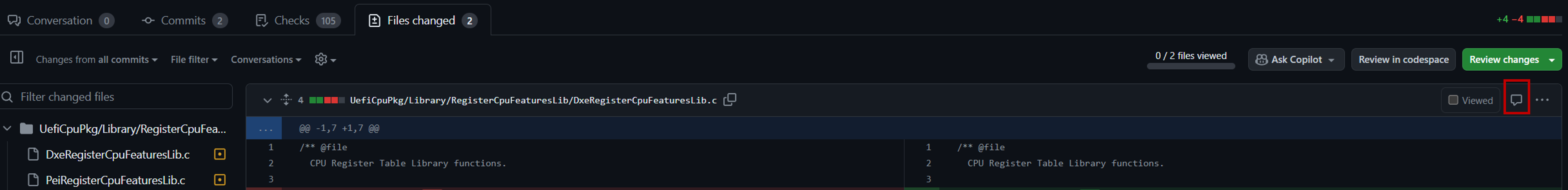
- Unlike a generic comment left in the PR, a comment in a code file must be resolved before the PR can be completed.
-
If you would like to leave a comment on a specific commit, it is recommended to leave a comment on the file and simply reference the commit in the comment. For example, "this change should be in commit
<commit A title>instead of commit<commit B title>". -
Ensure conversations in the PR follow the PR Conversation Resolution Process.
-
Note: An approval means you approve of all the changes applicable to you in the PR.
-
Apart from generic comments left in the PR and the comments left on specific files mentioned above, you can also leave a comment at the time you "Approve" or "Request changes". In the GitHub Web UI, click the "Files changed" tab and then "Review changes", select the appropriate radio box, leave your comment, and then click "Submit review".
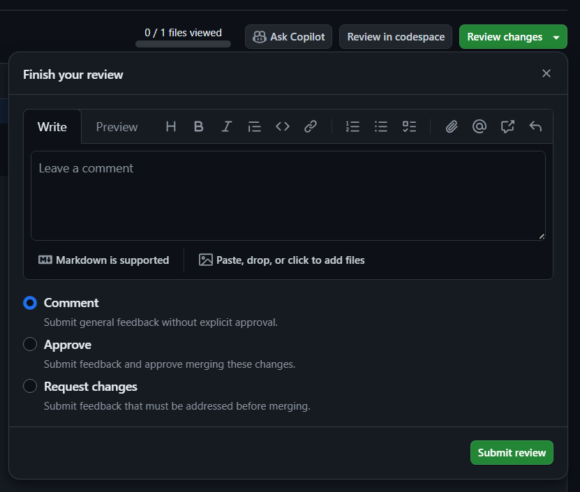
-
-
Each code area modified in the PR will have a list of reviewers and maintainers assigned to the path in Maintainers.txt. If at least one reviewer assigned to each code area has approved the PR, the
"push"label may be added to complete the PR.- Note: All PR status checks must succeed and there must be no merge conflicts for the PR to complete.
PR Conversation Resolution Process
All conversations must be resolved for a PR to be completed. This is the process used to resolve conversations.
- A PR author is allowed to resolve conversations after they have addressed feedback.
- After addressing feedback, a PR author is expected to leave a comment describing their resolution in the conversations.
- A conversation cannot be resolved until the PR author and commenter have reached an agreed upon resolution.
Maintainer Process for the edk2-platforms Repository
The generic rules from the main process applies, with the following additions:
- Maintainers are responsible for keeping their platform/driver ports buildable against an unmodified current version of edk2 and (if so required) edk2-non-osi. Unless given explicit permission by the repository owners (as was done for opensbi), platforms/drivers are not permitted additional external requirements beyond what is already present in those repositories.
- Platforms/drivers must document any build steps/options beyond the basic steps described in the top-level
Readme.md. They must also document the toolchains that are known working.
- Helper scripts to streamline building are fine, but since those tend to come with their own stack of dependencies, they must not be required for a basic build test.
- Pointing to a docker image is fine, as long as the toolchain versions in that docker image are also explicitly called out.
- Platforms/drivers must be buildable with current toolchain versions (i.e. no "build is only supported on Ubuntu 14.04 LTS").
Maintainer Process for the EDK II BaseTools Project
EDK II BaseTools project is a Tianocore-maintained project consisting of the python source files that make up EDK2 basetools. It provides an easy way to organize and share python code to facilitate reuse across environments, tools, and scripts. In the future, this project will be the only location of the EDK II BaseTools python source code, and the EDK II project will remove all BaseTools python source code.
Now, we are in the phase where the BaseTools python code is in both the edk2 repository and the edk2-basetools repository. The BaseTools maintainer should follow the following steps to keep the code in sync.
- After the patch gets reviewed, the maintainer creates a PR to the
edk-basetoolsrepo, and merges it into theedk2-basetoolsrepo if the CI checks pass. - Wait for the new version pip module generated in pypi.org.
- Update the
edk2-basetoolsvalue to the latest basetools pip module version from theedk2/pip-requirements.txtfile. Create a PR to the edk2 repo to trigger edk2 CI to do the packages build tests. - Create a pip-requirement patch and send it to community review.
- Get the Reviewed-by from the reviewers.
- Create a PR and merge the pip-requirement change to edk2 repository.
- Create a PR and merge the basetools patch to edk2 repository.
See Also
Github Access And Usage
Moved to SourceForge to Github Quick Start.
GitHub & Pull Request (PR) Tips
As of May 2024, the TianoCore project transitioned from a mailing list based contribution process to a pull request process. Since many community developers may not be familiar with essential GitHub and pull request features, this guide is meant to show various tips to improve your workflow making it easier to contribute and review changes in edk2.
-
- Forking the edk2 repository
- Setting up notifications for the edk2 repository
- Creating a Pull Request
- Viewing Changes in a Pull Request
- Leaving Feedback in a Pull Request
- Viewing Open & Closed Pull Requests
- Finding a commit
- Finding a Pull Request for a commit
- Contributing entirely in your Web browser
GitHub UI Key Features
Forking the edk2 Repository
Forking a repository on GitHub creates a copy of the original repository under your GitHub account, allowing you to freely experiment with changes without affecting the original project. You must create a fork of the edk2 repository to create a pull request. To fork the edk2 repository:
- Navigate to the edk2 repository on GitHub.
- Click on the "Fork" button in the upper-right corner of the repository page.
- Select your GitHub username where you want to fork the repository.
- See Fork a Repo for more information.
Once your fork is setup, you can push a branch to the fork with your changes and then create a pull request into the tianocore/edk2 repo from the branch on the fork.
When you fork a repository, you should understand how permissions and settings are transferred to protect your fork.
Setting Up Notifications for the edk2 Repository
Notifications help you stay informed about certain activities in the repository. Review the following links to better understand the types of notifications available and how to set them up:
GitHub also provides guidance for filtering emails in your email client. It is recommended to especially review the Filtering email notifications section to learn what options are available.
Creating a Pull Request
Creating a pull request is the primary way to contribute changes to a repository on GitHub. There are many ways to create a pull request depending on whether you are using the GitHub Web UI or a tool like GitHub Desktop, VS Code, the GitHub CLI, or another tool.
The quickest approach when using the GitHub Web UI is to push the branch to your forked repository and then visit the tianocore/edk2 repo. The UI will conveniently display an option to create a pull request from the branch you just pushed to your fork.
- See Creating a Pull Request for more information.
Create a Draft Pull request
Prior to the current pull request process, pull requests were created to test changes against CI and then closed. Now,
any pull requests that are not targeting completion to the master branch must be marked as a draft pull request.
This still allows PR status checks to run but it indicates that maintainers should not review the pull request.
To create a draft pull request in the GitHub Web UI, click the down arrow next to "Create Pull Request" and select "Create Draft Pull Request". An example of how to do this is shown in the link below.
Viewing Changes in a Pull Request
Pull request reviews can also happen in a number of different tools. When first getting started, try out a few options and see what works best for you. Many users start with the GitHub Web UI but find that it is not as feature-rich as other options.
For example, I prefer to review code within the context of the full codebase so surrounding code is readily displayed and I can easily search across the codebase while reviewing. This is why I tend to use VS Code with the GitHub PR extension when reviewing a non-trivial change. I can review code with the same level of IDE support used when writing code and it is easy to leave comments, code suggestions, and respond to conversations. It also allows code to easily be checked out locally to test the changes and make any modifications on top.
Suggested reading:
Leaving Feedback in a Pull Request
The edk2 project requires that conversations be resolved before a pull request can be merged. Conversations are typically resolved by clicking a "Resolve conversation" button. Comments left in a code file whether on a specific line of code or as a general file comment must be resolved.
If you would like to simply leave a comment without requiring a resolution, you can leave a comment outside of a file such as in the comment box at the bottom of the pull request.
The above link also shows how you can leave a code suggestion for a section of code in a pull request. The following link shows how the author of a pull request can apply a code suggestion.
Viewing Open & Closed Pull Requests
There are many ways to view pull requests. The most common view is to navigate to the "Pull requests" tab of the repository. There you can quickly filter by open/closed status, author, labels, review status, and more. In addition, the PR status check status is displayed next to each PR.
You can find all of the pull requests and issues you've created and been asked to review across repos specific to your account by going to the dashboard by clicking the buttons described in Viewing all of your issues and pull requests.
Finding a Commit
To locate a specific commit within the repository's history.
- Go to the repository on GitHub (e.g., edk2).
- Click on the "
<X> Commits" button where<X>is the number of commits currently in the selected branch. - Click the commit.
If you have a commit hash, for example 4b6ee06a090d956f80b4a92fb9bf03098a372f39, you can append it to the
repository URL to view the commit directly. For example, https://github.com/tianocore/edk2/commit/4b6ee06a090d956f80b4a92fb9bf03098a372f39.
Finding a Pull Request for a Commit
Once you have a commit hash/URL such as
https://github.com/tianocore/edk2/commit/4b6ee06a090d956f80b4a92fb9bf03098a372f39,
you can quickly find the associated pull request by looking for the pull request link next to the branch name. In the
example below, clicking #5639 will take you to the pull request.

Other tools also provide ways to find the pull request for a commit. For example, it is possible in the GitHub CLI to use:
>$ gh pr list --search "4b6ee06" --state merged
In an IDE like VS Code with the recommended extensions installed, you can simply hover over a line of modified code to see the commit and pull request information for the change:
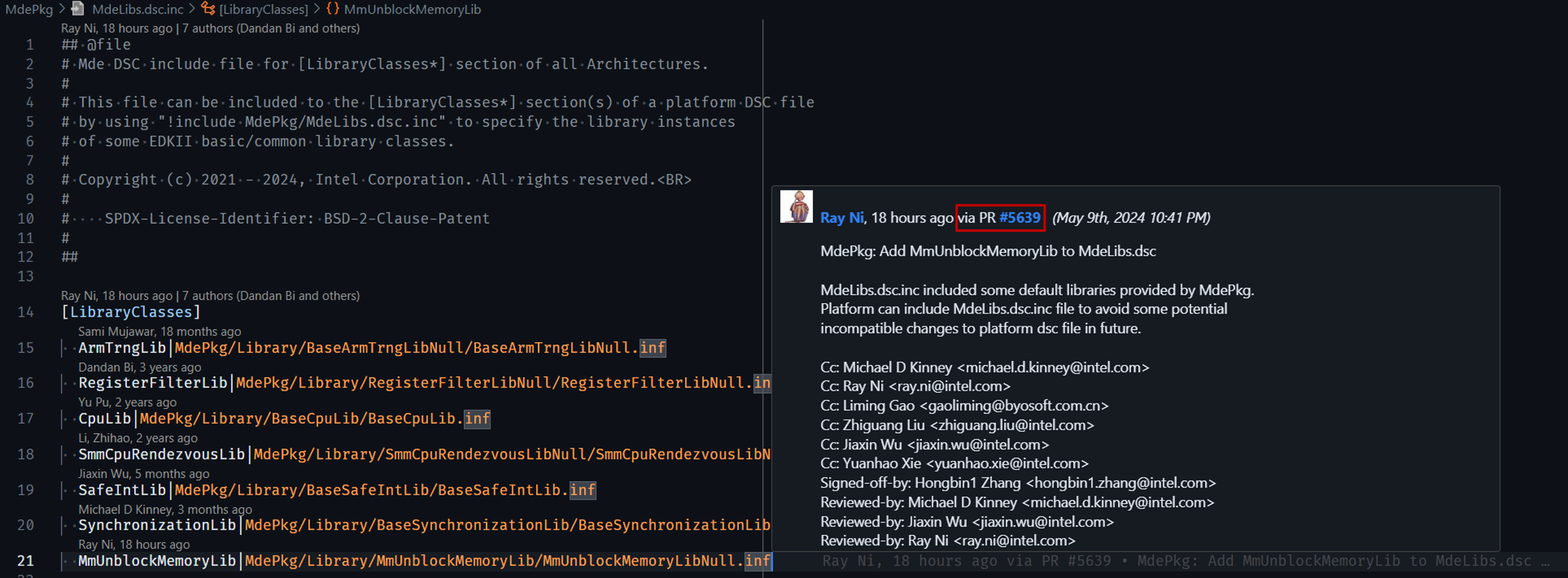
Contributing Entirely in Your Web Browser
If you contribute infrequently or want to make a quick change on a system without setting it up for development, you might be interested in GitHub Codespaces. Using Codespaces, you can work entirely in your Web browser in a feature rich environment that includes a terminal, code editor, and more to submit your change. GitHub provides a number of free hours per month for Codespaces usage.
The edk2 project provides a Fedora and Ubuntu dev container you can use for your Codespaces environment.
A lighter weight and completely free alternative to simply edit files your Web browser is to use the built-in editor in the GitHub Web UI called the github.dev web-based editor. This allows you to edit files in your browser, create branches, and PRs without having to clone anything locally. This might be useful if you are making very light changes such as editing text files or updating Python dependencies and your changes can entirely be tested in the PR status checks.
2. VS Code GitHub PR Plugin
Overview
The VS Code GitHub Pull Requests and Issues extension allows seamless integration of GitHub pull requests and issues directly within the VS Code editor. This provides a powerful interface for reviewing and managing pull requests without leaving your development environment.
Review's the extension's documentation to learn how to use it effectively.
It is recommended to install these extensions as well to make the most of git and GitHub integration in VS Code:
3. Official GitHub CLI Tool
GitHub CLI (gh) is the official command-line tool for interacting with GitHub repositories and pull requests. With GitHub CLI, you can interact with GitHub directly from the terminal. It is open-source and available for Linux, macOS, and Windows.
4. Official GitHub Desktop Application
GitHub Desktop is a user-friendly application for managing GitHub repositories on your desktop. If you find the command-line interface intimidating and would prefer not to use VS Code with extensions, the GitHub Desktop application is a great alternative.
It provides an intuitive interface for performing common Git operations, including creating branches, committing changes, and managing pull requests. If you are new to git, you might also find the GitHub desktop documentation helpful for getting started.
How To Contribute
Our community enables UEFI firmware and tools through various open source projects. Most of our efforts are currently related to the EDK II project, so if you are developer, then this is a good place to start contributing to our community.
UEFI developers are the primary focus of our community, but if you are interested in trying to use UEFI, then we have a page on how to start using UEFI.
There are several ways to participate in our community. Anyone can join our Mailing Lists to discuss UEFI related topics.
Developers
If you are a developer, and would like to make Code Contributions to our community:
- Review our Member Types which documents requirements for contributing code
- Review our Tasks page which documents some open projects
- Review our Code Style page which documents coding styles and commit log styles
- Review our Inclusive Language Guidelines page which documents banned words and recommended substitutions
- Review our https://tianocore-docs.github.io/EDK_II_Secure_Code_Review_Guide/draft/ prior to submitting a patch, along with creating a unit test and performing some static analysis
- Recommend following some of the practices at 1
- Do not post a patch to an unmitigated security issue. Instead follow guidelines at 2
- If a proposed set of patches also requires a change to UEFI or other industry standard specifications, then use the EDK II Code First Process.
Laszlo's Unkempt Git Guide For Edk2 Contributors And Maintainers
This document describes a deprecated process of contributing changes using patches on a mailing list. Information in this document may still be helpful for setting up your git configuration, but the latest process for contributing changes via pull requests is available in EDK II Development Process.
This is a quick and dirty, simplified and slightly modified description of my own edk2 workflow with git. It expressly defers to the EDK II Development Process article on the TianoCore wiki. It doesn't try to be generic, focuses only on GNU/Linux (that's what I use). It will not go into many details about git; if you are interested, you'll have to research those concepts on the web yourself.
Also, this is very specific to edk2. Other projects have different workflows.
Contributor workflow
-
§ Create an account on GitHub.
-
§ Enable SSH authentication for your account.
https://help.github.com/articles/generating-an-ssh-key/
When completing this step, you should end up with a new keypair under
~/.ssh/, for example:id_rsa_for_github id_rsa_for_github.puband the following stanza in your
~/.ssh/config:Host github.com User git IdentityFile ~/.ssh/id_rsa_for_github -
§ Fork the following repository on GitHub into your own GitHub account, using the GitHub web GUI:
[https://github.com/tianocore/edk2/](https://github.com/tianocore/edk2/)(My personal fork is at https://github.com/lersek/edk2/)
-
§ Clone the official edk2 repository to your local computer:
cd some-appropriate-directory git clone https://github.com/tianocore/edk2.git -
§ Implement the following git settings for your local clone, i.e., while standing in your local edk2 directory (these steps don't need customization):
git config am.keepcr true git config am.signoff true git config cherry-pick.signoff true git config color.diff true git config color.grep auto git config commit.signoff true git config core.abbrev 12 git config core.pager cat git config core.whitespace cr-at-eol git config diff.algorithm patience git config diff.ini.xfuncname '^\[[A-Za-z0-9_., ]+]' git config diff.renames copies git config format.coverletter true git config format.numbered true git config format.signoff false git config notes.rewriteRef refs/notes/commits git config sendemail.chainreplyto false git config sendemail.thread true git config sendemail.to devel@edk2.groups.io -
§ Also implement the following -- they need customization:
git config sendemail.smtpserver FQDN_OF_YOUR_LOCAL_SMTP_SERVER git config user.email "Your Email Address" git config user.name "Your Name" -
§ Create a file called
tianocore.templatesomewhere outside your edk2 clone, with the following contents. Note that the last line requires customization.[empty line] [empty line] Signed-off-by: Your Name <Your Email Address> -
§ Standing in your edk2 clone, implement the following setting (requires customization):
git config commit.template \ FULL_PATHNAME_OF_FILE_CREATED_IN_LAST_STEP -
§ Open the file
.git/info/attributes(create it if it doesn't exist), and add the following contents:
*.efi -diff *.EFI -diff *.bin -diff *.BIN -diff *.raw -diff *.RAW -diff *.bmp -diff *.BMP -diff *.dec diff=ini *.dsc diff=ini *.dsc.inc diff=ini *.fdf diff=ini *.fdf.inc diff=ini *.inf diff=ini -
§ Create a file called
edk2.diff.ordersomewhere outside your local clone, with the following contents:*.dec *.dsc.inc *.dsc *.fdf *.inf *.h *.vfr *.cFrom git version 1.9.0 onwards, this can be configured permanently for the current repository with
git config --add diff.orderFile <full path to edk2.diff.order>If using an older version of git, you need to pass this path in manually when generating patches.
-
§ Add your own fork of edk2 that lives on GitHub as a remote to your local clone:
git remote add -f --no-tags \ YOUR_GITHUB_ID \ git@github.com:YOUR_GITHUB_ID/edk2.git -
§ At this point you are ready to start developing. Refresh your local master branch from the upstream master branch:
git checkout master
git pull
The first command is extremely important. You should only run
git pullwhile you are standing on your local master branch that tracks (and never diverges from) the upstream master branch.These commands will fetch any new commits from upstream master, and fast-forward your local tracking branch to the new HEAD.
-
§ Create and check out a topic branch for the feature or bugfix that you would like to work on. The topic branch name requires customization of course.
git checkout -b implement_foo_for_bar_v1 master -
§ Make sure you have the build environment set up:
source edksetup.sh make -C "$EDK_TOOLS_PATH" -
§ Implement the next atomic, logical step in your feature or bugfix. Test that it builds and works. You should not cross module (driver, library class, library instance) boundaries within a single patch, if possible.
-
§ Add your changes gradually to the staging area of git (it is called the "index"):
git add -pThis command will ask you interactively about staging each separate hunk, for files that git already tracks. In order to stage the addition of a new file, use
git add pathnameFinally, for staging the removal of a file that git has been tracking, issue
git rm pathname -
§ When done, you can run
git statusThis will list the files with staged and unstaged changes. You can show the diff that is staged for commit:
git diff --stagedand also the diff that is not staged yet:
git diff -
§ If you are happy with the staged changes, run:
git commitThis will commit the staged changes to your local branch called
implement_foo_for_bar_v1. You created this branch in step 13.Before the commit occurs, git will fire up your preferred editor (from the
EDITORenvironment variable) for you to edit the commit message. The commit message will be primed from the template created in step 7 and configured in step 8.Above the template, you should add:
-
a subject line, no longer than 74-76 characters, consisting of
PackageName: ModuleName: summary of changes -
an empty line
-
one or more paragraphs that describe the changes in the patch. No line should be longer than 74 characters.
-
an empty line
-
One or more tags directly above the
Signed-off-byline (which comes from the template) that CC the package maintainers that are relevant for this specific patch. Consult theMaintainers.txtfile. For example, if you wrote a patch for OvmfPkg, add:Cc: Jordan Justen <jordan.l.justen@intel.com> Cc: Laszlo Ersek <lersek@redhat.com> Cc: Ard Biesheuvel <ard.biesheuvel@linaro.org> Cc: Anthony Perard <anthony.perard@citrix.com> Cc: Julien Grall <julien.grall@linaro.org>
-
-
§ When you have committed the patch, it is best to confirm it adheres to the edk2 coding style. Run:
python BaseTools/Scripts/PatchCheck.py -1 -
§ If the command in step 19 reports problems, modify the source code accordingly, then go back to step 16 and continue from there. However, as a small but important change for step 18, run
git commitwith the--amendoption:git commit --amendThis will squash your fixups into the last commit, and it will also let you re-edit the commit message (the
PatchCheck.pyscript can also find problems with the commit message format).Re-run step 19 as well, to see if your patch is now solid.
-
§ Write your next patch. That is, repeat this procedure (goto step 15) until you are happy with the series -- each single one of your patches builds and runs (implementing the next atomic, logical step in the bugfix or feature), and at the last patch, the feature / bugfix is complete.
-
§ It is now time to publish your changes for review.
(At this point, at the latest, it is important to review your full series using a git GUI; for example
gitk. Practically, any time you are in doubt, and especially before publishing patches, rungit statusandgitk(or another GUI tool) and go over your series.)First, we'll push your local branch to your personal repository on GitHub, under the same branch name.
git push YOUR_GITHUB_ID master implement_foo_for_bar_v1This command will connect to github using your remote configuration added in step 11, employing the SSH authentication configured in step 2.
It will update the master branch in your personal repo on GitHub to your local master branch (which in turn follows the official master branch, see step 12).
It will also push the topic branch you created under step 13.
-
§ Now we'll format the patches as email messages, and send them to the list. Standing in the root of your edk2 directory, run the following (note that the
-Ooption needs customization: please update the pathname to the file created in step 10):rm -f -- *.patch git format-patch \ --notes \ -O"/fully/qualified/path/to/edk2.diff.order" \ --subject-prefix="PATCH v1" \ --stat=1000 \ --stat-graph-width=20 \ master..implement_foo_for_bar_v1This command will generate an email file for each one of your commits. The patch files will be numbered. The file numbered 0000 is a cover letter, which you should edit in-place:
-
in the
Subject:line, summarize the goal of your series, -
in the message body, describe the changes on a broad level,
-
reference, by complete URL, the
implement_foo_for_bar_v1branch in your personal GitHub repo -- the one that you pushed in step 22, -
finally, add all of the
Cc:tags to the cover letter that you used across all of the patches. This will ensure that even if a maintainer is involved in reviewing one or two of your patches across the series, he or she will get a copy of your cover letter, which outlines the full feature or bugfix.
If
diff.orderFilehas been configured as described above, the -O parameter can be left out. -
-
§ Time to mail-bomb the list! Do the following:
git send-email               \
  --suppress-cc=author       \
  --suppress-cc=self         \
  --suppress-cc=cc           \
  --suppress-cc=sob          \
  --suppress-cc=misc-by      \
  --transfer-encoding=base64 \
  *.patch
(On Windows, you may have to move the
*.patchfiles to a dedicated temporary directory, and specify that directory on the command line, in place of the*.patchglob.)This command might ask you about sending the messages in response to another message (identified by
Message-Id). Just press Enter without entering anything.You might want to run the command first with the
--dry-runparameter prepended.The messages will be posted to the list only, and to the maintainers that you CC'd explicitly in the commit messages.
Once the messages are sent, you can remove the local patch files with:
rm -f -- *.patch -
§ On the list, you will get feedback. In the optimal case, each patch will get a
Reviewed-bytag (or anAcked-bytag) from at least one maintainer that is responsible for the package being touched by that patch. If you are lucky, you will also getTested-bytags from some of them.Once all tags are in place, one of the maintainers will pick up the entire series, update the commit messages to include the above tags (
Reviewed-by,Acked-by,Tested-by) at the bottom, and commit and push your patches to upstream master. If this happens, pop the champagne, and goto step 12. -
§ More frequently though, you will get requests for changes for some of your patches, while others of your patches will be fine, and garner
Reviewed-by,Acked-by, andTested-bytags. What you need to do in this case is:- create the next version of your local branch
- pick up the tags that you got on the list
- implement the requested changes
- mark the v2 changes on each patch outside of the commit message
- push the next version to your personal repo again
- post the next version to the list
In the following steps, we'll go through each of these in more detail.
-
§ Create the next version of your local branch. Run the following commands in your edk2 tree:
git checkout master
git pull

git checkout                  \
  -b implement_foo_for_bar_v2 \
  implement_foo_for_bar_v1

git rebase master implement_foo_for_bar_v2
These commands do the following: first they refresh (fast forward) your local master branch to the current upstream master.
Then they fork version 2 of your topic branch off of version 1 of the same. Finally version 2 of the topic branch is rebased, non-interactively, on top of the refreshed master branch.
The upshot is that at this point, you have an identical version of your series on top of refreshed master, under a name that states v2, without touching the original v1 series.
Theoretically the last command could run into conflicts, but those are unlikely for a low-churn project like edk2, and if you get those, you should ask for help on the list. Conflict resolution is outside of the scope of this writeup. For now we'll assume that your last command completes without errors.
-
§ Pick up the tags that you got on the list. Run the following command:
git rebase -i master implement_foo_for_bar_v2This will open your
EDITORwith a list of your patches, identified by commit hash and subject line, each prefixed with a rebase action. By default, the rebase action will bepick.You should carefully go through the feedback you received on the list for the v1 posting. (An email client that supports threading is a hard requirement for this.) For each v1 patch where you received a tag (
Reviewed-by,Tested-by,Acked-by), replace thepickaction withreword. Be sure not to modify anything else in the rebase action list.Once you modified these actions, save the file, and quit the editor. Git will now rebase your patches again (to the same refreshed local master branch), but now it will also stop at each patch that you marked
reword, and will let you edit the commit message for the patch. This is when you append the tags from the mailing list feedback to the very end of the commit message, underneath your ownSigned-off-bytag. Save the updated commit message and quit the editor; git will continue the rebase.Important: when you append the
Reviewed-by,Tested-by,Acked-bytags from the mailing list feedback to the very end of a given commit message, never retype those tags. Always cut and paste them with the clipboard instead. You have to treat those tags as opaque.If you mess up a commit message, don't panic. There are two options to bail out. First, you can update the next commit message to an empty text file. Git rebase will then stop and expect you to issue further commands at the normal shell prompt. This is when you run
git rebase --abortand everything will be exactly like at the end of step 27.
The second option if you mess up a commit message (and you notice too late, i.e., the rebase finishes), is just to repeat step 28, and fix up the commit message.
(There is a third option: the branch can be forcibly reset to a chronologically earlier HEAD, which you can collect from the reflog. But that is a very sharp tool and not recommended for now.)
At the end of this step, you will have picked up the feedback tags from the list, for each affected patch individually.
-
§ Implement the requested changes. For this you run again
git rebase -i master implement_foo_for_bar_v2but this time, you replace the
pickactions of the affected (= to be modified) patches withedit. My strong recommendation is to set theeditaction for exactly one patch in the series, and let the rest remainpick. (There are cases when this is not the best advice, but once you get in those situations, you won't need this guide.)Okay then, git will start the rebase, and it will stop right after the patch you marked as
editis committed. Your working tree will be clean (no changes relative to the staging index), your staging index will also be clean (no changes staged relative to the last commit -- which is the patch you marked asedit).At this point you modify the code as necessary, and build it and test it. Once satisfied, you run step 16 and step 17. After those steps, your working tree will be clean relative to the staging index, and the index will have all the necessary changes staged relative to the last commit (which you marked as
editin the rebase action list).Now, if you ran
git commitat this point (i.e., step 18 verbatim), then git would insert the staged changes as a separate patch into your series, so don't do that; that's most likely not your intent. Instead, run
git commit --amendwhich will squash your staged changes into the patch-to-be-edited.
(I am leaving out some editing action types here, such as: dropping a patch entirely, inserting a new patch, reordering patches, squashing patches together, and especially splitting up patches into smaller patches, and moving hunks between patches. Those are completely doable, and constitute the absolute power that git has over subversion, but they are definitely beyond these basics.)
Okay, your patch is fixed up now as the reviewer(s) requested; it builds, it runs (at the level expected at this stage into your series);
PatchCheck.pyis happy with it; and you have it committed. Time to run:git rebase --continueThis will complete the rebase.
You can repeat this step (step 29) as many times as necessary. Again, I recommend to run a full rebase per each patch that needs an edit.
A small caveat: if you significantly edit a patch, say, for the v3 posting, for which you have received a
Reviewed-byorTested-byearlier, you are supposed to drop these tags, because your significant edits render them stale. -
§ Mark the v2 changes on each patch outside of the commit message. This step is not strictly required, but it is a huge help for reviewers and maintainers.
Each time you finish a full rebase (an iteration of step 29), you should run your git GUI (
gitkor anything else), and locate the patch (by subject) that you just edited in step 29.Grab the SHA1 commit hash of that patch, and run:
git notes edit COMMIT_HASH_OF_THAT_PATCHGit will again fire up your text editor, and allow you to attach notes to the commit. The distinction between a commit message and commit notes is that the notes are ephemeral. They will be included in a special section of the patch email, but they will never be included in the commit message itself, on the upstream master branch. They are perfect for communicating v1 -> v2 -> v3 changes, per patch, during the evolution of a given patch series.
So, please format the notes as follows:
v2:
- frobnicate quux [Jordan]
- perturb xizzy [Laszlo]
No line should be longer than 72 characters in the notes, and each entry should preferably mark who suggested that specific change for the patch.
Save the notes file and quit your editor, git will apply the changes. If you need to reedit the note, just repeat this step (step 30).
Very importantly, every time you complete a rebase, your notes are preserved, even if you edit the patch itself (code or commit message) during the rebase. This is very important for v2 -> v3 updates, because in that case you can add the v3 section on top of v2 in the notes!
-
§ Push the next version to your personal repo again.
Practically, repeat step 22, but using the branch name
implement_foo_for_bar_v2.(It is very important that you never ever modify
implement_foo_for_bar_v1after you push it to your personal github repo. Namely, thisfeature_branch_vNkind of branch is supposed to reflect your vN mailing list posting precisely. Since your mailing list posting is read only (you cannot modify emails you sent), you must not modify the corresponding branches in your github repo either. If a new version is necessary, you'll post a new version, and you'll push a new branch too.) -
§ Post the next version to the list.
In practice, repeat step 23, with the following modifications:
-
The subject prefix should state
--subject-prefix="PATCH v2" -
The commit range given should be
master..implement_foo_for_bar_v2 -
The cover letter should reference the v2 branch pushed in step 31.
-
The cover letter should include or reference (with an URL to the mailing list archive) the cover letter of the v1 posting, and also summarize the v1->v2 changes.
Then repeat step 24.
-
This is it, more or less, for a contributor. Nonetheless, I recommend reading the rest even to contributors, because it will help them understand how maintainers are supposed to operate, and how their actions above assist maintainers in doing their work.
Maintainer workflow
-
§ You need the same settings in your edk2 clone as a contributor. This includes contributor step 1 through contributor step 11.
-
§ You get patches to review, either by CC, or you notice them on the list.
If you can immediately point out problems with (some of) the patches, do so. If you are pleased with (some of) the patches, respond with your
Reviewed-by, per patch. (Or, well, if you like it all, to the cover letter.)If you agree with a patch, more or less, but lack the expertise to review it in depth (possible for patches that target a package that you don't maintain), respond with your
Acked-by. -
§ When reviewing a v2, v3, ... posting of a series, focus on the changes. The contributor is expected to support you in this with:
-
Picking up your
Reviewed-byandAcked-bytags from your v1 review. You can skip re-reviewing those patches in v2, especially because contributor step 29 instructs the contributor to drop your earlierReviewed-byorAcked-byif he or she reworks the patch significantly. -
Listing the relative changes per patch, in the git-notes section. Refer to contributor step 30.
-
Summarizing the changes in the v2, v3, ... cover letters. Refer to contributor step 32.
-
-
§ Assuming the series has converged (i.e., all patches have gained the necessary
Reviewed-byand/orAcked-bytags), plus you have been "elected" as the lucky maintainer to apply and push the series, read on.(The following steps are also relevant if you would like to test the series, or if you would like to review each patch in the series against a fully up-to-date, complete codebase, with all the precursor patches from the series applied.)
-
§ The first attempt at applying the contributor's series is directly from emails. For this, you absolutely need a mail user agent (MUA) that allows you to save patch emails intact.
So save all the patch emails into a dedicated, new folder.
-
§ Refresh your local master branch.
git checkout master
git pull
Note that it is extremely important to switch to the master branch, with the checkout command above, before you run
git pull. -
§ Create an application/testing/review branch, and apply the patches from the files you saved in maintainer step 5, from within your MUA:
git checkout -b REVIEW_implement_foo_for_bar_vN master

git am dedicated_directory/*.eml
Now, this step can genuinely fail for two reasons. The first reason is very obscure and I'm sharing it only for completeness.
So the first reason is that the patch may create or delete files, which implies
/dev/nullfilenames in the git diff hunk headers. Because of thecore.whitespacesetting in contributor step 5 -- which we absolutely need due to the source files using CRLF line terminators in the internal git representation --, git-am might choke on those/dev/nulllines. This depends on theContent-transfer-encodingof the email that is saved in maintainer step 5.The second reason is that the master branch may have genuinely diverged from where it was when the contributor prepared his or her patches, on top of then-master. And the patches may no longer apply with git-am on top of current master.
If
git amabove fails for any reason at all, immediately issuegit am --abortand proceed to the next step, maintainer step 8. Otherwise, if
git amsucceeds, skip forward to maintainer step 11. -
§ As an alternative to maintainer step 7, here we'll grab the contributor's patches from his or her personal GitHub repo.
First add his or her personal repo as a remote to your local clone (this step only needs to be done once, during all of the collaboration with a given contributor):
git remote add --no-tags                           \
  HIS_OR_HER_GITHUB_ID                             \
  https://github.com/HIS_OR_HER_GITHUB_ID/edk2.git
At this point you should of course use the repo URL that the contributor shared in his or her cover letter, in contributor step 23 or -- for a v2, v3, ... post -- in contributor step 32.
-
§ Fetch any new commits and branches from the contributor's repo:
git fetch HIS_OR_HER_GITHUB_ID -
§ Now, set up a local, non-tracking branch off of the contributor's relevant remote branch. You know about the relevant branch again from contributor step 23 or contributor step 32, i.e., the cover letter.
git checkout --no-track \ -b REVIEW_implement_foo_for_bar_vN \ HIS_OR_HER_GITHUB_ID/implement_foo_for_bar_vN -
§ Rebase the contributor's series -- using your local branch that you created either in maintainer step 7 or in maintainer step 10 -- to the local master branch (which you refreshed from upstream master in maintainer step 6):
git rebase -i master REVIEW_implement_foo_for_bar_vNHere you should mark those patches with
rewordthat have receivedReviewed-by,Acked-by,Tested-bytags on the mailing list after the contributor's last posting. (Patches that garnered such tags in earlier versions are supposed to carry those tags already, due to contributor step 28.)When rewording the relevant patches, simply append the relevant
Reviewed-by,Acked-by,Tested-bytags from the mailing list feedback. (Refer to contributor step 28.)Now, this rebase has a much better chance to succeed than
git amin maintainer step 7, for two reasons again. The first reason is that the problem with the/dev/nullheaders just doesn't exist. The second reason is thatgit rebase, unlikegit am, knows whence you are rebasing, which helps it immensely in calculating conflict resolutions automatically.Nonetheless, the rebase might still fail, if meanwhile there have been intrusive / conflicting changes on the upstream master branch. If that happens, you can try to resolve the conflicts yourself, or you can ask the contributor to rebase his or her work on current upstream master, and to post it as the next version.
-
§ Okay, now you have the contributor's patches on top of your local master branch, with all the tags added from the mailing list. Time to build-test it! If the build fails, report it to the list, and ask the contributor for a new version.
(The OCD variant of this step is to build-test the contributor's series at each constituting patch, to enforce bisectability.)
-
§ Okay, the build test passes! Maybe you want to runtime test it as well. If you do, and it works, you can respond with a
Tested-byto the entire series on the list, and immediately add your ownTested-byto the patches as well. Employ maintainer step 11 accordingly. -
§ Time to push the patches to upstream master. Take a big breath :)
The steps below attempt to push the commits from your local
REVIEW_implement_foo_for_bar_vNbranch -- which is based off of your local master branch -- to the main github repo using a GitHub pull request, and move the upstream master branch forward to the final commit among those.If it succeeds, you deserve an alcoholic (or non-alcoholic) drink of your choice, you're done.
If a merge conflict is detected, then the reason is that another maintainer executed these steps in parallel, and moved forward the upstream master branch after your maintainer step 6, but before your maintainer step 14. If github accepted your pull request in this case, that may cause the other maintainer's pull request to fail.
Follow steps 7-9 from The maintainer process for the EDK II
project
substituting <new-integration-branch> with REVIEW_implement_foo_for_bar_vN.
-
§ Repeat the following steps:
-
maintainer step 6 -- Refresh your local master branch.
Do not forget the
git checkout masterpart in that step! -
maintainer step 11 -- Rebase the contributor's series.
No changes should be necessary, but if conflicts are found, those are due to the fresh commits pushed by the other maintainer, mentioned in maintainer step 14. The possible remedies are discussed in maintainer step 11 -- fix up the conflicts yourself, or ask the contributor to rebase and post a new version.
-
maintainer step 12 through maintainer step 14 -- rebuild, optionally retest, try pushing again.
-
Source Control
TianoCore has been managed in git, on github, since 2016 (and briefly in a temporary git mirror during the major Sourceforge outage of 2015). Before that, it was managed in subversion on Sourceforge, mirrored to git and cvs.
Certain artefacts of this history can be seen in older commits; the
first commit without a git-svn-id: tag is dd9044b310ae2be2ae989a522979feee86b39cc8.
Because, at least at the time of the migration, there wasn't a good mapping from git repo functionality to svn and cvs, we did not set up mirrors to these formats - https://github.com/tianocore is now the only canonical repository.
SourceForge To Github Quick Start
GitHub Help
GitHub (https://help.github.com/index.html) provides step-by-step instructions for user registration and basic features supported by GitHub.
GitHub EDK II Project Repositories
The EDK II project repository is available at https://github.com/tianocore/edk2.
Prebuilt Windows tools are available at https://github.com/tianocore/edk2-BaseTools-win32.
Please note that FatPkg is now included in the EDKII project repository, as of April 2016. Previously the FatPkg was in an independent repository which can be found at https://github.com/tianocore/edk2-FatPkg.
Content that is not released under an accepted open source license can be found at https://github.com/tianocore/edk2-non-osi.
How to Setup the EDK II Tree
Note: Some of the following examples use the Multiple Workspace feature to configure the EDK II BaseTools. More information on the Multiple Workspace feature can be found at the following location.
Linux Support
For EDKII project developers
- Clone the EDK II project repository
- git clone https://github.com/tianocore/edk2
- Change to the edk2 directory
- Build the tools
- make -C BaseTools
- Run the edksetup.sh script
- . edksetup.sh
When the above steps are done, you can work in the edk2 directory for code development.
For FatPkg developers
- Create a workspace directory
- Change to the workspace directory
- Clone the EDK II project repository
- git clone https://github.com/tianocore/edk2
- Clone the edk2-FatPkg repository to “FatPkg”
- git clone https://github.com/tianocore/edk2-FatPkg FatPkg
- Build the tools
- make -C edk2/BaseTools
- Set environment variables
- WORKSPACE – The workspace directory created above
- PACKAGES_PATH – Set it to $WORKSPACE/edk2
Example:
export WORKSPACE=/Sample/Path
export PACKAGES_PATH=$WORKSPACE/edk2
- Run the edksetup.sh script
- . edk2/edksetup.sh
When the above steps are done, the directory structure will look like:
 Sample
   └───Path (WORKSPACE)
      ├───edk2
      └───FatPkg
Windows Support
For EDKII project developers
- Create a workspace directory
- Change to the workspace directory
- Clone the EDK II project repository
- git clone https://github.com/tianocore/edk2
- Clone the edk2-BaseTools-win32 repository
- Set environment variables:
- EDK_TOOLS_BIN – Set it as the edk2-BaseTools-win32 directory
Example:
set EDK_TOOLS_BIN=c:\efi\test\edk2-BaseTools-win32
- Change to the edk2 directory
- Run the edksetup.bat script
When the above steps are done, the directory structure will look like:
 efi
   └───test (WORKSPACE)
      ├───edk2
      └───edk2-BaseTools-win32
For FatPkg developers
- Create a workspace directory
- Change to the workspace directory
- Clone the EDK II project repository
- git clone https://github.com/tianocore/edk2
- Clone the edk2-BaseTools-win32 repository
- Clone the edk2-FatPkg repository to “FatPkg”
- git clone https://github.com/tianocore/edk2-FatPkg FatPkg
- Set environment variables:
- WORKSPACE – The workspace directory created above
- PACKAGES_PATH – Set it to %WORKSPACE%\edk2
- EDK_TOOLS_BIN – Set it to %WORKSPACE%\edk2-BaseTools-win32
Example:
set WORKSPACE=c:\efi\test
set PACKAGES_PATH=%WORKSPACE%\edk2
set EDK_TOOLS_BIN=%WORKSPACE%\edk2-BaseTools-win32
- Run the edksetup.bat script
- edk2\edksetup.bat
When the above steps are done, the directory structure will look like:
efi
  └───test (WORKSPACE)
     ├───edk2
     ├───edk2-BaseTools-win32
     └───FatPkg
Please keep in mind that the EDK II project, FatPkg and edk2-BaseTools-win32 are independent Git repositories. Each of these repositories must be updated individually.
Development Process for the EDK II Project
The process is documented on the EDK II Development Process page.
See Also
EDK II Address Sanitizer Features
Current EDK II supports following kinds of address sanitizer features:
- Page/pool memory overflow detection (Heap Guard)
- PcdHeapGuardPropertyMask
- PcdHeapGuardPoolType
- PcdHeapGuardPageType
- NULL pointer access detection (NULL Detection)
- PcdNullPointerDetectionPropertyMask
- Use-After-Free page/pool memory detection (UAF Detection)
- PcdHeapGuardPropertyMask
- Global stack overflow detection (Stack Guard)
- PcdCpuStackGuard
- Local stack overflow detection (BaseStackCheckLib)
- -fstack-protector-all (MdePkg\Library\BaseStackCheckLib\BaseStackCheckLib.inf)
Heap Guard
to-be-done
EDK II Code Scanning
CodeQL is a code analysis engine developed by Github to automate security checks.
It is used for Code Scanning in the TianoCore edk2 repository.
Table of Contents
Overview
CodeQL is open source and free for open source projects. It is maintained by GitHub and naturally has excellent integration with GitHub projects. CodeQL uses a semantic code analysis engine to discover vulnerabilities in a number of programming languages (both compiled and interpreted).
TianoCore uses CodeQL C/C++ queries to find common programming errors and security vulnerabilities in firmware code. Many open-source queries are officially supported and comprise the vulnerability analysis performed against the database.
In addition, anyone can leverage the code analysis engine by writing a custom query. Information around writing a custom query is available in the official documentation.
The edk2 repository uses GitHub's Code Scanning feature (free for public repositories on GitHub.com) to show alerts directly in the repository and run CodeQL on pull requests and pushes to the repository.
Current CodeQL scanning results in the edk2 project are available in the "Actions" page of the GitHub repository.
A CodeQL command-line interface (CLI) is also available which can be run locally. A CodeQL CLI reference and manual are available in the documentation to learn how to use the CLI.
At a high-level, there's two main phases of CodeQL execution to be aware of.
- CodeQL database generation
- CodeQL database analysis
The CodeQL CLI hooks into the normal firmware build process to generate a CodeQL database. Once the database is generated, any number of CodeQL queries can be run against the database for analysis.
CodeQL analysis results can be stored in the SARIF (Static Analysis Results Interchange Format) file format.
SARIF files are JSON following the SARIF specification/schema. The files can be opened with SARIF viewers to more conveniently view the results in the file.
For example, the SARIF Viewer extension for VS Code can open a .sarif file generated by the CodeQL CLI and allow you to click links directly to the problematic line in source files.
In summary, the edk2 repository runs CodeQL on pull requests and CI builds. Any alerts will be flagged in the pull request status checks area. The queries used by the edk2 repository are stored in the edk2 CodeQL query set file.
CodeQL Usage in edk2
CodeQL provides the capability to debug the actual queries and for our (TianoCore) community to write our own queries and even contribute back to the upstream repo when appropriate. In other cases, we might choose to keep our own queries in a separate TianoCore repo or within a directory in the edk2 code tree.
This is all part of CodeQL Scanning. Information on the particular topic of running additional custom queries in Code Scanning is documented here in that page.
In addition, CodeQL offers the flexibility to:
- Build databases locally
- Retrieve databases from server builds
- Relatively quickly test queries locally against a database for a fast feedback loop
- Suppress false positives
- Customize the files and queries used in the edk2 project and quickly keep this list in sync between the server and local execution
Query Target List
While CodeQL can scan various languages including Python and C/C++, the TianoCore project is only focused on C/C++ checks at this time. TianoCore has an initial set of queries to evaluate shown below (checked boxes are done).
- ✅ cpp/conditionally-uninitialized-variable
- ✅ cpp/infinite-loop-with-unsatisfiable-exit-condition
- ✅ cpp/overflow-buffer
- ✅ cpp/pointer-overflow-check
- ✅ cpp/potential-buffer-overflow
- ⬜ cpp/toctou-race-condition
- ⬜ cpp/unclear-array-index-validation
- ⬜ cpp/unsafe-strncat
- ⬜ cpp/use-after-free
- ⬜ cpp/user-controlled-null-termination-tainted
- ⬜ cpp/wrong-number-format-arguments
- ⬜ cpp/wrong-type-format-argument
Additional queries completed:
Query Filtering in edk2
CodeQL query files (.ql files) contain metadata about the query. For example,
cpp/conditionally-uninitialized-variable
states the following about the query:
/**
 * @name Conditionally uninitialized variable
 * @description An initialization function is used to initialize a local variable, but the
 *              returned status code is not checked. The variable may be left in an uninitialized
 *              state, and reading the variable may result in undefined behavior.
 * @kind problem
 * @problem.severity warning
 * @security-severity 7.8
 * @id cpp/conditionally-uninitialized-variable
 * @tags security
 *       external/cwe/cwe-457
 */
edk2 automatically include queries against certain criteria using "query filters". For example, this could include any
problem query above a certain security-severity level. Or all queries with security in tags.
Because edk2 favors consistency in CI results, the project maintains a relatively fixed query set that is updated with individual queries over time.
Note: Additional queries can be found here as well - https://lgtm.com/search?q=cpp&t=rules
Process for Suggesting New Queries for edk2
New query adoption in edk2 can be proposed by sending an RFC to the TianoCore development mailing list (devel@edk2.groups.io) with the query link and justification for adopting the query in edk2.
Everyone is welcome to suggest new queries.
Query Enabling Process
Enabling a new query may trigger zero to thousands of alerts. Therefore, two paths are used to enable a new query in the project.
- A single patch series - The first set of patches fixes the issues needed for the query to pass. The later set of patches enables the query.
- A query enabling branch - A branch is created where multiple contributors can work together on fixing issues related to enabling a new query. Once the branch is ready, the history is cleaned up into a patch series that is submitted to the edk2 project.
(1) is recommended if the query is relatively simple to enable and one or two people are doing the work. (2) is recommended if a lot of effort is needed to fix issues for the query especially issues spanning across packages.
If a query is deemed fruitless during enabling testing, it can simply be rejected. The goal for CodeQL in edk2 is to enable an effective set of queries that improve the codebase. As the list of enabled queries grows, total CodeQL coverage will increase against active pull requests. We want to have relevant and effective coverage.
CodeQL in Pull Requests
TianoCore is enabling CodeQL in a step-by-step fashion. The goal with this approach is to make steady progress enabling CodeQL to become more comprehensive and useful while not impacting day-to-day code contributions.
Throughout the process described in this section, CodeQL Code Scanning is be a mandatory status check for edk2 pull requests.
Dismissing CodeQL Alerts
The following documentation describes how to dismiss alerts: Dismissing Alerts
Note: If query has a false positive a GitHub Issue can be submitted in the CodeQL repo issues page with the
false-positivetag to help improve the query.
CodeQL CLI Local Commands
The CodeQL CLI can be used as follows to wrap around the edk2 build
process (MdeModulePkg in this case) to generate a database in the directory cpp-database. The example shown uses
stuart build commands.
codeql database create cpp-database --language=cpp --command="stuart_ci_build -c .pytool/CISettings.py -p MdeModulePkg
-a IA32,X64 TOOL_CHAIN_TAG=VS2019 Target=DEBUG --clean" --overwrite
The following command can be used to generate a SARIF file
(called query-results.sarif) from that database with the results of the
cpp/conditionally-uninitialized-variable
query:
codeql database analyze cpp-database codeql\cpp\ql\src\Security\CWE\CWE-457\ConditionallyUninitializedVariable.ql --format=sarifv2.1.0 --output=query-results.sarif
SARIF logs can be read by log viewers such as the Sarif Viewer extension for VS Code.
The CodeQL Project
CodeQL is an actively maintained project. Here is a comparison of edk2 commit activity versus CodeQL for reference:
Because CodeQL does maintain a strong open-source presence, the TianoCore community should be able to file issues and pull requests into the project.
The original RFC for adoption of CodeQL in edk2 is available here for reference: Adoption of CodeQL in edk2
EDK II Continuous Integration
Summary of pre-commit and post-commit Continuous Integration services that improve the quality of commits made to EDK II repositories. The sections below list the Continuous Integration services that are active and plans for future enhancements and extensions to these services.
Phase 1 (edk2 repository only) - Activated November 11, 2019
- Use a combination of GitHub, Azure Pipelines, Mergify, and edk2-pytool features.
- GitHub Pull Requests + Labels, Branch Protections, Notifications
- Mergify Pull Request Rules with auto commit if all checks pass
- 3 pre-commit jobs in Azure Pipelines (PatchCheck, Windows/VS, Linux/GCC). Goal is to complete all pre-commits check in under 10 minutes.
- 2 post-commit jobs in Azure Pipelines (Windows/VS, Linux/GCC). Post commit
status provided at top of
edk2/masterReadme.md. - EDK II Pytool Library
- EDK II Pytool Extensions
- GitHub Issue
- Original RFC Proposals
- Enable the following pre-commit checks PatchCheck CharEncodingCheck CompilerPlugin DependencyCheck DscCompleteCheck GuidCheck LibraryClassCheck SpellCheck
- TianoCore EDK II Maintainers Team permissions reduced from 'Write" to "Triage"
- EDK II Maintainers must use GitHub pull request with 'push' label to request
a branch to be strict rebase merged into
edk2/master. If all checks pass, then the patches in the pull request are automatically added toedk2/master. If any check fails, then email notifications are sent and details of the failure are available through Azure Pipelines test results. - Personal builds available to all EDK II developers using a GitHub pull request without the 'push' label set. If all checks pass, then a notification email is sent and the pull request is closed. If any checks fails, then email notifications are sent and the details of the failure are available through Azure Pipelines test results.
- GitHub References
- GitHub Command line Utility (
gh) to perform GitHub operations - Azure Pipelines References
- Mergify References
EDK II Continuous Integration Administration
Proposed Pre-Commit Checks in Phase 2
- Verify no non-ASCII characters in modified files
- Verify no binary files in set of modified files
Proposed Pre-Commit Checks in Phase 3
- Run ECC on modified files
- Verify modified modules/libs build
- Run available Host Based tests against modified modules/libs
Post Commit Checks
- Build all modules/libs/platforms that consume modified content
Daily Builds
- Build critical packages
- Build critical platforms
- Verify that Doxygen Documentation can be generated
Weekly Builds
- Build all packages
- Build all platforms
- Publish Doxygen Documentation to a web site
Release Builds
- Same as weekly builds
- Full regression testing
- Publishes binary files to release pages
Possible Continuous Integration Actions
- PatchCheck.py
- Verify no non-ASCII characters in modified source files
- Verify no binary files in set of modified files
- Verify Package Dependency rules in modified files
- Verify modified modules/libs build
- Run Host Based tests against modified modules/libs
- cppcheck
- ECC (EFI Code Checker)
- Difficult to address all warnings/issues/false positives reported
- May need to maintain an exception list
- Static Analysis against modified modules/libs
- CLANG static analysis
- Coverity: https://scan.coverity.com/
- Difficult to address all warnings/issues/false positives reported
- May need to maintain an exception list
- pyflakes (for python sources)
- pylama (for python sources)
- Generate Package Documentation (Doxygen based)
- Build all Packages/Platforms for all supported CPU architectures (IA32, X64, ARM, AARCH64, EBC), all supported tool chains (VS2015, VS2017, GCC5, XCODE5), and all supported build targets (DEBUG, RELEASE, NOOPT). Needs further discussion on required coverage.
- Boot platforms to UEFI Shell
- Run UEFI SCTs and collect results for platforms
- Linaro LAVA CI
- Boot platforms to OS(s)
- Integration/Regression tests that require full OS boots
- Build binary releases of components (e.g. UEFI Shell, OVMF)
Possible Platform Testing Actions
- OVMF
- IA32 DXE boot tests
- X64 DXE boot tests
- ArmVirt QEMU boot tests
- S3 enabled tests
- SMM_REQUIRE enabled tests
- Boot using both KVM and QEMU environments
- HTTPS Boot Tests
- UEFI Secure Boot Sanity Testing
- Enroll UEFI Secure Boot Keys
- UEFI Secure Boot testing of "unsigned" images
- UEFI Secure Boot testing of "signed but not recognized" images
- UEFI Secure Boot testing of "signed and accepted" images
- UEFI Secure Boot testing of "signed but blacklisted" images
- Project that offers a python script that automates communicating with the UEFI shell over the emulated serial port. Used in downstream package builds, for packaging a pre-enrolled variable store template file.
Evaluations and Supporting Background Materials
- Background
- GitHub Continuous Integration services https://github.com/marketplace/category/continuous-integration
- Jenkins Evaluation
- GitLab Evaluation
- Contacts
- Laszlo Ersek lersek@redhat.com
- Philippe Mathieu-Daudé philmd@redhat.com
- https://gitlab.com/philmd/edk2/pipelines
- Contacts
- Azure Pipeline Evaluation for CPU Archs, tool chain tags, and build targets
- Azure Pipelines Evaluation with HBFA integration
- Contacts
- To work with this branch and run tests immediately, all you need to do is:
pip install --upgrade -r requirements.txt
stuart_setup -c .\CISettings.py
stuart_update -c .\CISettings.py
stuart_ci_build -c .\CISettings.py --Tool_Chain VS2017
- Branch is monitored for CI and PR gating in the following Azure build pipeline. https://dev.azure.com/tianocore/edk2-ci-play/_build?definitionId=12
- Results show that this CI process is running build CI and DSC checking and automatically running a host-based unit test and all of the results are visible in a single view. https://dev.azure.com/tianocore/edk2-ci-play/_build/results?buildId=216&view=ms.vss-test-web.build-test-results-tab https://dev.azure.com/tianocore/edk2-ci-play/_build/results?buildId=215&view=ms.vss-test-web.build-test-results-tab
- Depends on pip installable tool from the following TianoCore repos
- Documentation for edk2-pytools https://github.com/tianocore/edk2-pytool-library/tree/master/docs https://github.com/tianocore/edk2-pytool-extensions/tree/master/docs
Performance Infrastructure
User can use the Perf macros in edk2/MdePkg/Include/Library/PerformanceLib.h to log the performance information.
The performance information are collected in FPDT record format directly by performance libraries and then saved in ACPI
Firmware Performance Data Table(FPDT).
Thus the performance data can be dumped both in UEFI Shell and OS by tools to parse FPDT in ACPI table.
Performance Enable
(1) Make sure the Library instances are used correctly in different phase.
(2) Make sure ACPI is enabled on your platform.
(3) Make sure report progress status code is enabled on your platform.
It's required because performance data are collected through reporting progress status code.
You will not get the performance data if it's not enabled.
(PcdReportStatusCodePropertyMask: BIT0-Enable Progress Code)
(4) Set PcdPerformanceLibraryPropertyMask=1.
(5) If you want to use DP command in shell to dump performance data,
you can add ShellPkg/DynamicCommand/DpDynamicCommand/DpDynamicCommand.inf on your platform
Notes: If you want to filter some performance data, please check the configuration of PcdPerformanceLibraryPropertyMask in below PCD part for more information.
Performance Dump Tool
-
UEFI Shell tool: DP
(1) Use DP command:
You can build ShellPkg/DynamicCommand/DpDynamicCommand/DpDynamicCommand.inf on your platform,
then you can input DP command in shell directly to get the performance data.(2) Use DP application:
You can build ShellPkg/DynamicCommand/DpDynamicCommand/DpApp.inf,
then you can use DP Application to dump performance data.DP command and application read the installed FPDT ACPI table itself to get the performance data.
Performance modules
Performance library instances
1. edk2/MdeModulePkg/Library/PeiPerformanceLib
This library instance provides infrastructure for PEIMs(including PeiCore) to log performance data.
It will create FPDT record to save the performance data and pass the FPDT records to DxeCorePerformanceLib through
Guided Hob.
2. edk2/MdeModulePkg/Library/SmmPerformanceLib
This library instance provides infrastructure for SMM drivers to log performance data.
It consumes SMM PerformanceMeasurement Protocol published by SmmCorePerformanceLib to log performance data.
3. edk2/MdeModulePkg/Library/SmmCorePerformanceLib
This library instance is used by SmmCore. It will:
- Cache the performance data in SmmCore.
- Publish SMM PerformanceMeasurement protocol consumed by SmmPerformanceLib to log the performance data in SMM.
- Report the performance data in SMM phase (FPDT records) to the FirmwarePerformanceDataTableSmm driver.
4. edk2/MdeModulePkg/Library/DxePerformanceLib
This library instance provides infrastructure for DXE drivers to log performance.
It consumes PerformanceMeasurement Protocol published by DxeCorePerformanceLib to log performance data.
5. edk2/MdeModulePkg/Library/DxeCorePerformanceLib
This library instance is used by DxeCore. It will:
- Cache the performance data in DxeCore.
- Cache the performance data from PEI phase in Guided HOB passed by PeiPerformanceLib
- Publish the PerformanceMeasurement protocol consumed by DxePerformanceLib to log the performance data in DXE phase.
- Communicates with FirmwarePerformanceDataTableSmm driver to get the performance data in SMM phase.
- Report all the performance data(FPDT records) to the FirmwarePerformanceDataTableDxe driver.
Performance drivers
1. edk2/MdeModulePkg/Universal/Acpi/FirmwarePerformanceDataTablePei
This modules collects performance data for:
-
S3 Resume Performance Record:
S3ResumePerformanceRecord.ResumeCount
S3ResumePerformanceRecord.FullResume
S3ResumePerformanceRecord.AverageResumeS3 resume module reports status code of EFI_SW_PEI_PC_OS_WAKE.
FirmwarePerformanceDataTablePei module listens to the status code and save the value of
ResumeCount, FullResume and AverageResume. -
Boot performance records on S3 boot path reported by PeiPerformanceLib through Guided Hob.
And it will update the ACPI FPDT with new collected data.
This module is used in S3 boot.
2. edk2/MdeModulePkg/Universal/Acpi/FirmwarePerformanceDataTableSmm
This module collects performance data for:
-
S3 Suspend Performance Record:
S3SuspendPerformanceRecord.SuspendStart
S3SuspendPerformanceRecord.SuspendEndPlatform/chipset codes report SuspendStart status code when S3 state is triggered, report SuspendEnd status code when go to sleep.
FirmwarePerformanceDataTableSmm listens to the status code to save the time data.
Progress Code for S3 Suspend start:
PROGRESS_CODE_S3_SUSPEND_START = (EFI_SOFTWARE_SMM_DRIVER | (EFI_OEM_SPECIFIC | 0x00000000)) = 0x03078000gEfiMdeModulePkgTokenSpaceGuid.PcdProgressCodeS3SuspendStart|0x03078000|UINT32|0x30001032Progress Code for S3 Suspend end:
PROGRESS_CODE_S3_SUSPEND_END = (EFI_SOFTWARE_SMM_DRIVER | (EFI_OEM_SPECIFIC | 0x00000001)) = 0x03078001gEfiMdeModulePkgTokenSpaceGuid.PcdProgressCodeS3SuspendEnd|0x03078001|UINT32|0x30001033 -
Boot performance records in SMM phase reported by SmmCorePerformanceLib.
It will pass the boot performance records in SMM phase to DxeCorePerformanceLib through SMM communocation. This module is used in normal boot and S3 boot.
3. edk2/MdeModulePkg/Universal/Acpi/FirmwarePerformanceDataTableDxe
This module collects performance data for:
-
Firmware Basic Boot Performance Record:
BasicBootPerformanceRecord.ResetEnd
Platform SEC library caches the time stamp of ResetEnd through SecPerformancePpi.
And SecCore passes the SecPerformancePpi to PeiCore as notification type and add SecPerformancePpiCallback function to get SEC performance data and build Guided HOB to convey the performance data to DXE phase. So in PEI phase, SecPerformancePpiCallback is called, and then ResetEnd data can be got in DXE phase through Guided HOB. Currently FirmwarePerformanceDataTableDxe gets ResetEnd data from the Guided HOB.BasicBootPerformanceRecord.OsLoaderLoadImageStart
BasicBootPerformanceRecord.OsLoaderStartImageStart
Core codes (UefiBootManagerLib) report the status code.
FirmwarePerformanceDataTableDxe listens to the status code to get and save the time data.
Progress Code for OS Loader LoadImage start.
PROGRESS_CODE_OS_LOADER_LOAD = (EFI_SOFTWARE_DXE_BS_DRIVER | (EFI_OEM_SPECIFIC | 0x00000000)) = 0x03058000
gEfiMdeModulePkgTokenSpaceGuid.PcdProgressCodeOsLoaderLoad|0x03058000|UINT32|0x30001030Progress Code for OS Loader StartImage start.
PROGRESS_CODE_OS_LOADER_START = (EFI_SOFTWARE_DXE_BS_DRIVER | (EFI_OEM_SPECIFIC | 0x00000001)) = 0x03058001
gEfiMdeModulePkgTokenSpaceGuid.PcdProgressCodeOsLoaderStart|0x03058001|UINT32|0x30001031BasicBootPerformanceRecord.ExitBootServicesEntry
FirmwarePerformanceDataTableDxe registers callback function when ExitBootServices Event is signaled and save the time data.BasicBootPerformanceRecord.ExitBootServicesExit
FirmwarePerformanceDataTableDxe listens to the status code of EFI_SW_BS_PC_EXIT_BOOT_SERVICES to save the time data. -
All boot performance records reported by DxeCorePerformanceLib.
And it will install FPDT to ACPI table.
This module is used in normal boot.
PCD
PcdPerformanceLibraryPropertyMask
User can configure it to enable the performance infrastructure and also can filter some uninterested performance
data.
The meaning of each bits in PcdPerformanceLibraryPropertyMask as below:
-
BIT0 - Enable Performance Measurement.
-
BIT1 - Disable Start Image Logging.
-
BIT2 - Disable Load Image logging.
-
BIT3 - Disable Binding Support logging.
-
BIT4 - Disable Binding Start logging.
-
BIT5 - Disable Binding Stop logging.
-
BIT6 - Disable all other general Perfs.
-
BIT1-BIT6 are evaluated when BIT0 is set.
So PcdPerformanceLibraryPropertyMask=0: disable performance infrastructure.
PcdPerformanceLibraryPropertyMask=1: enable performance infrastructure.
PcdPerformanceLibraryPropertyMask=3: filter the performance data of Start Image behavior.
......
PcdEdkiiFpdtStringRecordEnableOnly
Control the FPDT record format used to store the performance entry when performance enable. PcdEdkiiFpdtStringRecordEnableOnly=TRUE: FPDT_DYNAMIC_STRING_EVENT_RECORD will be used to store every performance Entry. PcdEdkiiFpdtStringRecordEnableOnly=FALSE: different FPDT records will be used to store different performance entries.
Notes: The configuration of this PCD may impact the tool to parse the ACPI FPDT to dump the performance data.
Current DP tool in ShellPkg can dump the performance data regardless of the PcdEdkiiFpdtStringRecordEnableOnly setting
EDK II Dashboard
Note: this page is no longer maintained. Information is here for historical purposes and will be archived in an upcoming site revision.
|
EDK II BIOS Enabling Dashboard – January 21, 2014 |
Updates in red |
|
UEFI specs |
||
|---|---|---|
|
Description |
Revision |
Notes |
|
Intel UDK2010 page, with links to all kits and latest release
|
SR1.UP1.P1 |
http://sourceforge.net/apps/mediawiki/tianocore/index.php?title=UDK2010 |
|
UEFI Spec |
2.4 A Dec 2013 |
http://www.uefi.org Click Specifications -> Download Specifications, fill out form, and click Submit. |
|
UDK2010 documents (.chm and html)
|
SR1.UP1.P1 Jul 2013 |
all docs http://sourceforge.net/projects/edk2/files/UDK2010%20Releases/UDK2010.SR1.UP1.P1/UDK2010.SR1.UP1.P1-Documents.zip/download individual docs https://sourceforge.net/projects/edk2/files/EDK_II_Libraries/UDK2010.SR1.UP1.P1/ |
|
UEFI Driver Writer’s Guide |
1.01 Mar 2012 |
http://sourceforge.net/apps/mediawiki/tianocore/index.php?title=Driver_Developer |
|
Platform Initialization (PI) spec |
1.3 Jul 2013 |
http://www.uefi.org Click Specifications -> Download Specifications, fill out form, and click Submit. |
|
UEFI Shell spec |
2.0 Errata A May 2012 |
http://www.uefi.org Click Specifications -> Download Specifications, fill out form, and click Submit. |
|
UEFI other |
||
|---|---|---|
|
Description |
Revision |
Notes |
|
UEFI Mantis access |
Mantis is the UEFI ECR (Engineering Change Request) portal
|
|
|
Intel UEFI Driver and Application Tool Resources |
||
|
How to enable UEFI Secure Boot |
http://sourceforge.net/apps/mediawiki/tianocore/index.php?title=How_to_Enable_Security http://sourceforge.net/apps/mediawiki/tianocore/index.php?title=SecurityPkg |
|
|
UEFI Training videos |
http://sourceforge.net/apps/mediawiki/tianocore/index.php?title=Training |
|
|
Driver Developer page |
http://sourceforge.net/apps/mediawiki/tianocore/index.php?title=Driver_Developer |
|
|
UDK main page |
||
|
UDK 2010 roadmap |
http://sourceforge.net/apps/mediawiki/tianocore/index.php?title=RoadMap |
|
|
UEFI tools |
||
|---|---|---|
|
Description |
Revision |
Notes |
|
UEFI Driver Wizard |
0.11 Mar 2012 |
Open source program designed to accelerate the development of new UEFI drivers using a GUI-based template generator. http://sourceforge.net/apps/mediawiki/tianocore/index.php?title=Driver_Developer |
|
shell |
||
|---|---|---|
|
Description |
Revision |
Notes |
|
UEFI Shell |
2.0 Aug 2011 |
http://sourceforge.net/apps/mediawiki/tianocore/index.php?title=UDK2010 |
|
EDK II App Dev Kit (EADK)
|
A2 May 2011 |
http://sourceforge.net/apps/mediawiki/tianocore/index.php?title=UDK2010 |
|
EDK II shell porting guide |
http://sourceforge.net/apps/mediawiki/tianocore/index.php?title=Porting_an_EDK_Shell_Extension |
|
|
Shell 2.0 documentation |
||
|
user documentation |
||
|---|---|---|
|
Description |
Revision |
Notes |
|
EDK II User Manual |
0.7 Mar 2010 |
|
|
EDK II Module Writer’s Guide |
0.7 Mar 2010 |
|
|
EDK II C Coding Standards |
2.0 Dec 2014 |
http://sourceforge.net/projects/edk2/files/Specifications/EDK2_C_Coding_Standards_2_0.pdf/download |
|
EDK II Performance Optimization |
1.0 Feb 2010 |
|
|
EDK II packages |
http://sourceforge.net/apps/mediawiki/tianocore/index.php?title=EDKII_Packages |
|
|
FAQ and whitepapers |
||
|---|---|---|
|
Description |
Revision |
Notes |
|
EDK II and other FAQs |
http://sourceforge.net/apps/mediawiki/tianocore/index.php?title=Member_FAQ |
|
|
EDK II Build Decoded |
0.0.2 WW11 2012 |
http://sourceforge.net/projects/edk2/files/General%20Documentation/EDK_II_Build_Decoded.pdf/download |
|
How to create Visual Studio solution for code tree |
1.0 May 2012 |
|
|
EDK II SMM call topology |
0.3.1 October 2012 |
|
|
How EDK II Platform Reference Code is dispatched |
1.0 May 2012 |
|
|
Build integration of Reset Vector: example for a UDK2010 platform |
1.0 May 2012 |
|
|
forums |
|
|---|---|
|
Description |
Notes |
|
EDK II project home page |
|
|
EDK II support page |
|
|
EDK II source code changes mailing list |
|
|
EDK II developer discussion mailing list |
|
|
EDK II search mailing lists |
http://sourceforge.net/search/?group_id=288620&type_of_search=mlists |
|
user contributions |
|
|---|---|
|
Description |
Notes |
|
StartCore |
|
|
EDK II Build Data Viewer |
https://github.com/01org/edkiibuilddataviewer/ A Windows application to view all EDK II build log files, and display and quickly find where PCDs and GUIDs are defined, what source files are used in a build, and more! |
|
EFI info, may be useful |
||
|---|---|---|
|
Description |
Revision |
Notes |
|
EFI Shell Developer Guide |
0.91 |
|
|
EFI Shell Command Manual |
1.1 |
|
|
EFI Shell User’s Guide |
1.0 |
|
|
EFI Shell Getting Started Guide |
0.31 |
|
|
HII spec |
0.92 |
|
|
Intel Framework specs collection |
||
Minimum Platform Architecture
The Minimum Platform Architecture (MPA) creates guidelines for how to design, enable improvements in quality and security on open source platform initialization development on firmware for Intel products.
MinPlatformPkg
The main MinPlatform Package (MinPlatformPkg) provides a consistent boot flow and well-defined interfaces to support board functions.
- How to download and build https://github.com/tianocore/edk2-platforms/blob/master/Platform/Intel/Readme.md
EDK II Minimum Platforms
-
Kaby Lake MinPlatform - EDK II platform firmware on 7th Generation Intel® Core™ Processors and chipsets (formerly Kaby Lake platforms).
-
Project Olympus (Purley MinPlatform) - EDK II platform firmware for the Open Compute Project (OCP) Intel XSP Motherboard.
Note: Purley board support is no longer available in the codebase.
-
Whiskey Lake MinPlatform - EDK II platform firmware on 8th Generation Intel® Core™ Processors and chipsets (formerly Whiskey Lake platforms).
Resources
- Open Source Firmware Conference (OSFC) Presentation on Minimum Platform Architecture (Sept 2019)
- EDK II Minimum Platform Architecture Specification
- A Tour Beyond BIOS Open Source IA Firmware Platform Design Guide in EDK II (v 2)
Modules
The EDK Module Structure Explained
The following three tables explain the structure of the EDK source code.
- Module Maintainers: a list of who is responsible for the module. This reponsibility includes ensuring proper management of defects, enhancements and code quality of changes to code that falls within this module.
- Directory to Module Table: this table explains the relationship between the CVS directories and the EDK Module List
- Definition to Module Table: this table explains the definition of each module
Important Links: EFI and Framework Open Source Defect Resolution Process EDK Project Roles and Responsibilities Questions?
| | Module | Maintainer/Owner |
| ATA | Stanely Chen |
| BDS | Charlie Xia |
| CirrusLogic | Charile Xia |
| Compression | Mike Rothman |
| Console | Charile Xia |
| CSM | Nickel Shao |
| DataHub | Charile Xia |
| Debug | Sean Shang |
| Disk | Charile Xia |
| DxeCore | Mike Rothman |
| Dxelpl | Mike Rothman |
| EBC | Hua Fang |
| EDK IPF Tip | Jason Liu |
| FAT | Penny Gao |
| Flash | Stanely Chen |
| Generic Definition | Jiewan Yao |
| Library | Hua Fang |
| Logo | Michael Krau |
| Memory Test | Charile Xia |
| Network | Michael Krau |
| PCI | Penny Gao |
| PeiCore | Rui Sun |
| Runtime | Mike Rothman |
| SCSI | Stanely Chen |
| Security | Mike Rothman |
| Shell | Hua Fang |
| StatusCode | Mike Rothman |
| Timer | Jean Wang |
| Tools | Liming Gao |
| UI | Mike Rothman |
| USB | Penny Gao |
| Variable | Stanely Chen |
| WinNT | Jean Wang |
| Other | Michael Krau |
EDK Module Maintainer List
| \Edk\Foundation\Core\Dxe | DxeCore |
| \Edk\Foundation\Core\Pei | PeiCore |
| \Edk\Foundation\Cpu | IA32CPU |
| \Edk\Foundation\Efi | Generic definition |
| \Edk\Foundation\Framework | Generic definition |
| \Edk\Foundation\Guid | Refer to Definitions to Module table |
| \Edk\Foundation\Include | Refer to Definitions to Module table |
| \Edk\Foundation\Library\CustomizedDecompress | Compression |
| \Edk\Foundation\Library\Dxe | Library |
| \Edk\Foundation\Library\EfiCommonLib | Library |
| \Edk\Foundation\Library\Pei | Library |
| \Edk\Foundation\Library\RuntimeDxe\EfiRuntimeLib | Runtime |
| \Edk\Foundation\Ppi | Refer to Definitions to Module table |
| \Edk\Foundation\Protocol | Refer to Definitions to Module table |
| \Edk\Other\Maintained\Application | Application |
| \Edk\Other\Maintained\Tools | Tools |
| \Edk\Other\Maintained\Universal\Disk\FileSystem\Fat | FAT |
| \Edk\Sample\Bus\Pci\AtapiPassThru | ATA |
| \Edk\Sample\Bus\Pci\CirrusLogic | CirrusLogic |
| \Edk\Sample\Bus\Pci\IdeBus | ATA |
| \Edk\Sample\Bus\Pci\PciBus | PCI |
| \Edk\Sample\Bus\Pci\Uhci | USB |
| \Edk\Sample\Bus\Pci\Undi | Network |
| \Edk\Sample\Bus\Scsi | SCSI |
| \Edk\Sample\Bus\Usb | USB |
| \Edk\Sample\Bus\WinNtThunk | WinNT |
| \Edk\Sample\Chipset\WinNtThunk | WinNT |
| \Edk\Sample\Cpu\DebugSupport\Dxe\ia32 | Debug |
| \Edk\Sample\Cpu\DebugSupport\Dxe\ipf | Debug |
| \Edk\Sample\Cpu\WinNtThunk | WinNT |
| \Edk\Sample\Include | WinNT |
| \Edk\Sample\Library\Dxe\WinNt | WinNT |
| \Edk\Sample\Platform\Generic\Dxe\ConPlatform | Console |
| \Edk\Sample\Platform\Generic\Dxe\GenericBds | BDS |
| \Edk\Sample\Platform\Generic\Dxe\PlatformBds | WinNT |
| \Edk\Sample\Platform\Generic\Logo | Logo |
| \Edk\Sample\Platform\Generic\MonoStatusCode | StatusCode |
| \Edk\Sample\Platform\Generic\Pei\Capsule | Capsule |
| \Edk\Sample\Platform\Generic\RuntimeDxe\FvbService | Flash |
| \Edk\Sample\Platform\Generic\RuntimeDxe\StatusCode | StatusCode |
| \Edk\Sample\Platform\IPF | EDK IPF Tip |
| \Edk\Sample\Platform\Nt32 | WinNT |
| \Edk\Sample\Tools | Tools |
| \Edk\Sample\Universal\Console | Console |
| \Edk\Sample\Universal\DataHub | DataHub |
| \Edk\Sample\Universal\Debugger | Debug |
| \Edk\Sample\Universal\Disk | Disk |
| \Edk\Sample\Universal\DxeIpl | DxeIpl |
| \Edk\Sample\Universal\Ebc | EBC |
| \Edk\Sample\Universal\FirmwareVolume | Flash |
| \Edk\Sample\Universal\GenericMemoryTest | MemoryTest |
| \Edk\Sample\Universal\MonotonicCounter | Flash |
| \Edk\Sample\Universal\Network | Network |
| \Edk\Sample\Universal\Runtime | Runtime |
| \Edk\Sample\Universal\Security | Security |
| \Edk\Sample\Universal\UserInterface | UI |
| \Edk\Sample\Universal\Variable | Variable |
| \Edk\Sample\Universal\WatchdogTimer | Timer |
Directory-to-Module Table
| Edk\Foundation\Ppi\BaseMemoryTest | MemoryTest |
| Edk\Foundation\Ppi\FlashMap | Flash |
| Edk\Foundation\Ppi\PeiInMemory | DxeIpl |
| Edk\Foundation\Ppi\Security | Security |
| Edk\Foundation\Ppi\StatusCodeMemory | StatusCode |
| Edk\Foundation\Guid\AcpiTableStorage | ACPI |
| Edk\Foundation\Guid\AlternateFvBlock | Flash |
| Edk\Foundation\Guid\Bmp | Logo |
| Edk\Foundation\Guid\BootState | BDS |
| Edk\Foundation\Guid\Capsule | Capsule |
| Edk\Foundation\Guid\CompatibleMemoryTested | BDS |
| Edk\Foundation\Guid\ConsoleInDevice | Console |
| Edk\Foundation\Guid\ConsoleOutDevice | Console |
| Edk\Foundation\Guid\DataHubRecords | DataHub |
| Edk\Foundation\Guid\EfiShell | Application |
| Edk\Foundation\Guid\FlashMapHob | Flash |
| Edk\Foundation\Guid\HotPlugDevice | Console |
| Edk\Foundation\Guid\IoBaseHob | IPF |
| Edk\Foundation\Guid\MemoryAllocationHob | ERM |
| Edk\Foundation\Guid\MemoryTypeInformation | DxeCore |
| Edk\Foundation\Guid\PciHotPlugDevice | PCI |
| Edk\Foundation\Guid\PciOptionRomTable | PCI |
| Edk\Foundation\Guid\PeiFlushInstructionCache | DxeCore |
| Edk\Foundation\Guid\PeiPeCoffLoader | DxeCore |
| Edk\Foundation\Guid\PeiPerformanceHob | Performance |
| Edk\Foundation\Guid\PeiTransferControl | DxeCore |
| Edk\Foundation\Guid\PrimaryConsoleInDevice | Console |
| Edk\Foundation\Guid\PrimaryConsoleOutDevice | Console |
| Edk\Foundation\Guid\PrimaryStandardErrorDevice | Console |
| Edk\Foundation\Guid\StandardErrorDevice | Console |
| Edk\Foundation\Guid\StatusCode | StatusCode |
| Edk\Foundation\Guid\StatusCodeCallerId | StatusCode |
| Edk\Foundation\Guid\SystemNvDataGuid | Flash |
| Edk\Foundation\Include\Ebc | Ebc |
| Edk\Foundation\Include\EfiCommon.h | Generic definition |
| Edk\Foundation\Include\EfiDebug.h | Debug |
| Edk\Foundation\Include\EfiDepex.h | Generic definition |
| Edk\Foundation\Include\EfiFlashMap.h | Flash |
| Edk\Foundation\Include\EfiPerf.h | Performance |
| Edk\Foundation\Include\EfiPxe.h | Network |
| Edk\Foundation\Include\EfiSpec.h | Generic definition |
| Edk\Foundation\Include\EfiStdArg.h | Generic definition |
| Edk\Foundation\Include\EfiVariable.h | Variable |
| Edk\Foundation\Include\EfiWorkingBlockHeader.h | Flash |
| Edk\Foundation\Include\Ia32 | Generic definition |
| Edk\Foundation\Include\IndustryStandard\Acpi.h | ACPI |
| Edk\Foundation\Include\IndustryStandard\pci22.h | PCI |
| Edk\Foundation\Include\IndustryStandard\scsi.h | SCSI |
| Edk\Foundation\Include\IndustryStandard\Tcpa11.h | Security |
| Edk\Foundation\Include\IndustryStandard\usb.h | USB |
| Edk\Foundation\Include\Ipf | Generic definition |
| Edk\Foundation\Include\Pei | Generic definition |
| Edk\Foundation\Include\Tiano.h | Generic definition |
| Edk\Foundation\Include\TianoApi.h | Generic definition |
| Edk\Foundation\Include\TianoCommon.h | Generic definition |
| Edk\Foundation\Include\TianoDevicePath.h | Generic definition |
| Edk\Foundation\Include\TianoError.h | Generic definition |
| Edk\Foundation\Include\TianoTypes.h | Generic definition |
| Edk\Foundation\Protocol\ConsoleControl | Console |
| Edk\Foundation\Protocol\CpuIO | Generic definition |
| Edk\Foundation\Protocol\CustomizedDecompress | Compression |
| Edk\Foundation\Protocol\DebugAssert | Debug |
| Edk\Foundation\Protocol\DebugMask | Debug |
| Edk\Foundation\Protocol\DiskInfo | Disk |
| Edk\Foundation\Protocol\EfiOEMBadging | Logo |
| Edk\Foundation\Protocol\ExtendedSalBootService | Runtime |
| Edk\Foundation\Protocol\ExtendedSalGuid | Runtime |
| Edk\Foundation\Protocol\FaultTolerantWriteLite | Flash |
| Edk\Foundation\Protocol\FirmwareVolumeDispatch | Flash |
| Edk\Foundation\Protocol\FvbExtension | Flash |
| Edk\Foundation\Protocol\GenericMemoryTest | MemoryTest |
| Edk\Foundation\Protocol\GuidedSectionExtraction | Flash |
| Edk\Foundation\Protocol\IdeControllerInit | ICH |
| Edk\Foundation\Protocol\IncompatiblePciDeviceSupport | PCI |
| Edk\Foundation\Protocol\IsaAcpi | IsaBus |
| Edk\Foundation\Protocol\IsaIo | IsaBus |
| Edk\Foundation\Protocol\LoadPe32Image | DxeCore |
| Edk\Foundation\Protocol\PciHostBridgeResourceAllocation | PCI |
| Edk\Foundation\Protocol\PciHotPlugInit | PCI |
| Edk\Foundation\Protocol\PciHotPlugRequest | PCI |
| Edk\Foundation\Protocol\PciPlatform | PCI |
| Edk\Foundation\Protocol\Performance | Performance |
| Edk\Foundation\Protocol\PlatformMemTest | MemoryTest |
| Edk\Foundation\Protocol\Print | UI |
| Edk\Foundation\Protocol\PxeDhcp4 | Network |
| Edk\Foundation\Protocol\PxeDhcp4Callback | Network |
| Edk\Foundation\Protocol\ScsiIo | SCSI |
| Edk\Foundation\Protocol\SecurityPolicy | Security |
| Edk\Foundation\Protocol\Tcp | Network |
| Edk\Foundation\Protocol\TianoDecompress | Compression |
| Edk\Foundation\Protocol\UgaSplash | BDS |
| Edk\Foundation\Protocol\UsbAtapi | USB |
| Edk\Foundation\Protocol\VariableStore | Variable |
| Edk\Foundation\Protocol\VirtualMemoryAccess | MemoryTest |
Definition-to-Module Table
Platform Initialization (PI) Boot Flow
<imgsrc="https://raw.githubusercontent.com/tianocore/tianocore.github.io/master/images/PI_Boot_Phases-tn.jpg>
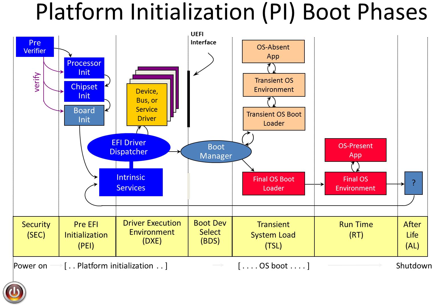
Security (SEC) Phase The Security (SEC) phase is the first phase in the PI Architecture architecture and is responsible for the following: * Handling all platform restart events
- Creating a temporary memory store
- Serving as the root of trust in the system
- Passing handoff information to the PEI Core
In addition to the minimum architecturally required handoff information, the SEC phase can pass optional information to the PEI Core, such as the SEC Platform Information PPI or information about the health of the processor. UEFI.org -PI VOLUME 1: Platform Initialization Specification 1.2 Pre-EFI Initialization Core Interface
Pre-EFI Initialization (PEI) Phase The Pre-EFI Initialization (PEI) phase of the PI Architecture specifications (hereafter referred to as the “PI Architecture”) is invoked quite early in the boot flow. Specifically, after some preliminary processing in the Security (SEC) phase, any machine restart event will invoke the PEI phase. The PEI phase will initially operate with the platform in a nascent state, leveraging only onprocessor resources, such as the processor cache as a call stack, to dispatch Pre-EFI Initialization Modules (PEIMs). These PEIMs are responsible for the following: * Initializing some permanent memory complement
- Describing the memory in Hand-Off Blocks (HOBs)
- Describing the firmware volume locations in HOBs
- Passing control into the Driver Execution Environment (DXE) phase
Philosophically, the PEI phase is intended to be the thinnest amount of code to achieve the ends listed above. As such, any more sophisticated algorithms or processing should be deferred to the DXE phase of execution. The PEI phase is also responsible for crisis recovery and resuming from the S3 sleep state. For crisis recovery, the PEI phase should reside in some small, fault-tolerant block of the firmware store. As a result, it is imperative to keep the footprint of the PEI phase as small as possible. In addition, for a successful ACPI S3 resume, the speed of the resume is of utmost importance, so the code path through the firmware should be minimized. These two boot flows also speak to the need to keep the processing and code paths in the PEI phase to a minimum. The implementation of the PEI phase is more dependent on the processor architecture than any other phase. In particular, the more resources the processor provides at its initial or near initial state, the richer the interface between the PEI Foundation and PEIMs. As such, there are several parts of the following discussion that note requirements on the architecture but are otherwise left architecturally dependent. UEFI.org -PI VOLUME 1: Platform Initialization Specification 1.2 Pre-EFI Initialization Core Interface
Driver eXecution Environment (DXE) Phase The Driver Execution Environment (DXE) phase is where most of the system initialization is performed. Pre-EFI Initialization (PEI), the phase prior to DXE, is responsible for initializing permanent memory in the platform so that the DXE phase can be loaded and executed. The state of the system at the end of the PEI phase is passed to the DXE phase through a list of position-independent data structures called Hand-Off Blocks (HOBs). HOBs are described in detail in the Platform Initialization Hand-Off Block Specification. There are several components in the DXE phase: * “DXE Foundation”
- “DXE Dispatcher”
- A set of “DXE Drivers”
The DXE Core produces a set of Boot Services, Runtime Services, and DXE Services. The DXE Dispatcher is responsible for discovering and executing DXE drivers in the correct order. The DXE drivers are responsible for initializing the processor, chipset, and platform components as well as providing software abstractions for system services, console devices, and boot devices. These components work together to initialize the platform and provide the services required to boot an operating system. The DXE phase and Boot Device Selection (BDS) phases work together to establish consoles and attempt the booting of operating systems. The DXE phase is terminated when an operating system is successfully booted. The Dxe Core is composed of boot services code, so no code from the Dxe Core itself is allowed to persist into the OS runtime environment. Only the runtime data structures allocated by the Dxe Core and services and data structured produced by runtime DXE drivers are allowed to persist into the OS runtime environment. UEFI.org -PI VOLUME 2: Platform Initialization Specification 1.2 Driver Execution Environment Core Interface
Boot Device Selection (BDS) Phase The Boot Manager in DXE executes after all the DXE drivers whose dependencies have been satisfied have been dispatched by the DXE Dispatcher. At that time, control is handed to the Boot Device Selection (BDS) phase of execution. The BDS phase is responsible for implementing the platform boot policy. System firmware that is compliant with this specification must implement the boot policy specified in the Boot Manager chapter of the UEFI 2.0 specification. This boot policy provides flexibility that allows system vendors to customize the user experience during this phase of execution. The Boot Manager must also support booting from a short-form device path that starts with the first node being a firmware volume device path. The boot manager must use the GUID in the firmware volume device node to match it to a firmware volume in the system. The GUID in the firmware volume device path is compared with the firmware volume name GUID. If a match is made, then the firmware volume device path can be appended to the device path of the matching firmware volume and normal boot behavior can then be used. The BDS phase is implemented as part of the BDS Architectural Protocol. The DXE Foundation will hand control to the BDS Architectural Protocol after all of the DXE drivers whose dependencies have been satisfied have been loaded and executed by the DXE Dispatcher. The BDS phase is responsible for the following: * Initializing console devices
- Loading device drivers
- Attempting to load and execute boot selections
If the BDS phase cannot make forward progress, it will reinvoke the DXE Dispatcher to see if the dependencies of any additional DXE drivers have been satisfied since the last time the DXE Dispatcher was invoked. UEFI.org -PI VOLUME 2: Platform Initialization Specification 1.2 Driver Execution Environment Core Interface
Transient System Load (TSL) Phase TSL is the 1st stage of the boot process where the OS loader is an EFI application.
Run Time (RT) Phase UEFI has a limited set of Runtime (RT) Services that are available after the Operating System boots and takes over the system. The primary runtime services enable the OS to read and write environment variables. There are also services that abstract the Real Time Clock, produce an monotonically increasing count, and support updates of firmware components via capsules. It is legal for OS to call UEFI runtime services using virtual addressing, so some of the runtime services are involved in making sure the code is callable from a given virtual address space. Making a virtual call is a one way gate, and the OS must request virtual calling when it boots and provide the firmware with the virtual mappings for the physical addresses required by the runtime firmware. The firmware then fixes it self up so that the next call can be made from the virtual address space. Due to this complexity of managing virtual calling runtime code in UEFI is usually isolated into runtime only drivers.
After Life (AF) Phase After the Operating System takes over from the BDS via its boot (TSL), only a small set of UEFI is left behind. If the hardware or OS crashes, firmware could try and implement some form of recovery or remediation action. This is the After life. UEFI and PI do not spec any required behavior in this phase.
Glossary
See Acronyms for glossary and acronym information.
StartCore
Note: this page is no longer maintained. Information is here for historical purposes and will be archived in an upcoming site revision.
Demo EDK II project StartCore http://edk2-startcore.sourceforge.net/
ArmPkg Ds5
Set up ARM DS-5 for UEFI development
This tutorial uses DS5 v5.12. Even if this tutorial is based on Linux; it should also work on Windows (after converting the file paths).
1. Start DS-5.
Note: This tutorial assumes DS-5 has been configured to debug your target (hardware or RTSM model). Help can be found here to add your RTSM model to DS-5 if not already done: http://infocenter.arm.com/help/index.jsp?topic=/com.arm.doc.dui0446i/CIHECHJE.html
2. Import the Tianocore project from the Sourceforge repository
Note: To install the Eclipse Git plugin in DS-5, see: http://www.eclipse.org/egit/ Before installing the git (or svn) plugin, check your Eclipse version (Help > About Eclipse Platform). Example, Eclipse 3.7 = Indigo The list of plugins for this Eclipse Platform version is available at http://download.eclipse.org/releases/indigo
- File > Import ...
- Git > Projects from GIT
The Sourceforge git repository (mirror of svn) is
git://tianocore.git.sourceforge.net/gitroot/tianocore/edk2. The main
branch is the 'master' branch; it is not required to import the other
branches. 
3. After the GIT repository has been imported, select 'Use the New
Project wizard' from the window 'Select a wizard to use for importing
projects'. 
And choose 'Makefile Project with Existing Code' in 'C/C++ project'

4. It is safer to create a development branch to separate your
development from the public repository.

5. Build the UEFI firmware for your platform. Example for the ARM RTSM Versatile Express Cortex A9x4, defined by the DSC file: ArmPlatformPkg/ArmVExpressPkg/ArmVExpress-RTSM-A9x4.dsc
- Project > Properties
 ArmDs5-tutorial-5.png
-
Change the default 'make' Build command to use the Tianocore Makefile:
make -f ArmPlatformPkg/Scripts/Makefile
 ArmDs5-tutorial-5-2.png
- Add the Environment Variables:
- EDK2_DSC=ArmPlatformPkg/ArmVExpressPkg/ArmVExpress-RTSM-A9x4.dsc
 ArmDs5-tutorial-6.png
- The supported environment variables are:
EDK2_ARCH=ARM|IA32|X64|... (default: ARM)
EDK2_TOOLCHAIN=RVCTLINUX|ARMLINUXGCC|ARMGCC|... (default: RVCTLINUX)
EDK2_BUILD=DEBUG|RELEASE (default: DEBUG)
EDK2_MACROS=...
 ArmDs5-tutorial-7.png
Note: On Windows, it is required to add the locations of nmake
and the prebuilt binaries of the Tianocore BaseTools to the PATH
environment variable.
You can add a similar PATH to your project environment variables in
addition to the environment variables above:
ArmDs5-tutorial-7.png
Note: On Windows, it is required to add the locations of nmake
and the prebuilt binaries of the Tianocore BaseTools to the PATH
environment variable.
You can add a similar PATH to your project environment variables in
addition to the environment variables above:
PATH=C:\Program Files\Microsoft Visual Studio 9.0\VC\bin; C:\git\edk2\BaseTools\Bin\Win32;${Path}
6. Build your project
- Project > Build All
 ArmDs5-tutorial-8.png
7. Switch to the DS-5 Perspective
ArmDs5-tutorial-8.png
7. Switch to the DS-5 Perspective
8. Create a new Debug Configuration

Prior to DS-5 v5.11, you need to edit the model configuration file in the DS-5 Configuration Database:
sudo vim /usr/local/DS-5/sw/debugger/configdb/Boards/ARM/RTSM_VE_Cortex_A9x4/a9_bare_metal.xml
Add the model parameter to the entry :
-C motherboard.flashloader0.fname="[YOUR_WORKSPACE_FULLPATH]/edk2/Build/ArmVExpress-RTSM-A9x4/DEBUG_RVCTLINUX/FV/RTSM_VE_CORTEX-A9_EFI.fd"
From DS-5 v5.11, these parameters can be passed through the DS-5 User
Interface. 
**Note:**To get the list of supported parameters:
/usr/local/DS-5/bin/RTSM_VE_Cortex-A9_MPx4 -l
9. In the 'Debugger' tab, select 'Connect Only'
**Note:**If your development platform waits for a firmware at a specific location, you can for instance load the binary into the target binary from 'Execute debugger commands' using the following script:
interrupt
if $pc==0
restore Build/ArmVExpress-RTSM-A9x4/DEBUG_RVCTLINUX/FV/RTSM_VE_CORTEX-A9_EFI.fd binary 0x8000000
end
This development method might be useful during firmware bring up when flashing the new firmware takes a significant amount of time.
Example of using DS-5 with the ARM Fast Model:

Note: On Windows to have a better support of the UEFI Serial output when using the Fast Model, it is recommended to use Putty instead of the default telnet terminal. Putty can be started at any time after the ARM Fast Model has been started. The default Fast Model telnet connection is localhost:5000.
10. To debug UEFI you can use the UEFI Python scripts for DS-5 (included in EDK2 repository):
- Example for loading all the symbols at the current 'PC' (Program Counter Register) position with DRAM from '0x80000000' to '0x80000000+0x40000000'
- source edk2/ArmPlatformPkg/Scripts/Ds5/cmd_load_symbols.py -m (0x80000000,0x40000000)
- Example for loading all the symbols loaded in DRAM from '0x80000000' to '0x80000000+0x4000000'
- source edk2/ArmPlatformPkg/Scripts/Ds5/cmd_load_symbols.py -m (0x80000000,0x40000000) -a
- Example for loading all the symbols at the current 'PC' (Program Counter Register) position with a Firmware Volume from '0x08000000' to '0x08000000+0x00280000'. Mainly useful during the XIP phase (SEC + PEI before relocation to DRAM)
- source edk2/ArmPlatformPkg/Scripts/Ds5/cmd_load_symbols.py -f (0x08000000,0x00280000)
- Example for loading all the symbols for the platform with a Firmware Volume at 0x08000000 and DRAM at 0x80000000:
- source edk2/ArmPlatformPkg/Scripts/Ds5/cmd_load_symbols.py -f (0x08000000,0x00280000) -m (0x80000000,0x40000000) -a
Note: If you build UEFI with the build report file 'report.log' in your EDK2 root directory (add '-y report.log' to your build command to generate this file) then the script will parse the report.log to get the address of the Firmware Volume and System Memory for your current platform. This convenient solution is not recommended if you work with multiple platforms. The current EDK2 BaseTools (23/10/2012) do not handle well changing the build options without cleaning the build.
- source edk2/ArmPlatformPkg/Scripts/Ds5/cmd_load_symbols.py
To have the list of all supported arguments:
- source edk2/ArmPlatformPkg/Scripts/Ds5/cmd_load_symbols.py -h
If you are not familiar with the platform, the way to get arguments for the script cmd_load_symbols.py is to get those information from the DSC and FDF EDK2 files of your platform. Example: -f (0x08000000, 0x00280000) comes from the base address and size of the FD file in ArmPlatformPkg/ArmVExpressPkg/ArmVExpress-RTSM-A9x4.fdf
[FD.RTSM_VE_Cortex-A9_EFI]
BaseAddress   = 0x08000000|gArmTokenSpaceGuid.PcdFdBaseAddress  # The base address of the Firmware in NOR Flash.
Size          = 0x00280000|gArmTokenSpaceGuid.PcdFdSize         # The size in bytes of the FLASH Device
ErasePolarity = 1
-m (0x80000000, 0x40000000) is the base address and size of the DRAM. This information is also available in ArmPlatformPkg/ArmVExpressPkg/ArmVExpress-RTSM-A9x4.dsc:
  # System Memory (1GB)
  gArmTokenSpaceGuid.PcdSystemMemoryBase|0x80000000
  gArmTokenSpaceGuid.PcdSystemMemorySize|0x40000000
Note 1: DS-5 does not currently recognise '*.iii' files as ARM assembly files. It is the reason why when stopping the DS-5 debugger and calling the script 'cmd_load_symbols.py' a single function may appear in the callstack. A workaround is to add the '*.iii' extension to the ARM assembly files:
Window > Preferences, General > Editors > File Associations
With this extension association the full callstack should be displayed.
Note 2: It is expected to see the warning messages after executing the command 'cmd_load_symbols.py':
Warning: not possible to load symbols from /home/olimar01/edk2/Build/Fat/RELEASE_RVCTLINUX/ARM/FatPkg/EnhancedFatDxe/Fat/DEBUG/Fat.dll Warning: not possible to load symbols from /home/olimar01/edk2/Build/Fat/RELEASE_RVCTLINUX/ARM/ShellPkg/Shell/DEBUG/Shell.dll
Because the Fat and Shell binaries come as pre-built binaries. If you want to rebuild these binaries for your platform: ArmPkg-Binaries
Note 3: DS-5 Debugger’s editor does not recognize the '*.iii' as assembly files. The workaround is to add a file association for "*.iii" to "ARM Assembler Editor" in DS-5 Eclipse: Window > Preferences, General > Editors > File Associations
ArmPkg Sct
Debugging UEFI Self Certification Test (SCT)
1. Build UEFI for your targeted ARM RTSM (RealTime System Model). See ArmPlatformPkg-ArmVExpressPkg for more complete instructions.
For this tutorial we will use ARM Versatile Express Cortex A9x4 RTSM:
cd $EDK2_ROOT
. edksetup.sh `pwd`/BaseTools
build -a ARM -p ArmPlatformPkg/ArmVExpressPkg/ArmVExpress-RTSM-A9x4.dsc -t ARMLINUXGCC
2. Build SCT binaries. Rebuilding the binaries will ensure the SCT package matches your SCT sources code that will ease the debugging. See the README attached to your SCT source package for the correct build instructions.
Example with the latest SCT source package (UEFI 2.3.1 SCT October 2012):
export PATH=/opt/DS-5/bin:$PATH
SctPkg/BuildArmSct.sh RVCT
Note: The first line is to add the ARM compiler (RVCT toolchain) to your PATH. The location of your RVCT toolchain might be different.
3. Create a MMC card with your newly built version of SCT and the EDK Shell binary (required to start SCT)
mkfs.vfat -C -n MMC_SD_CARD /tmp/mmc.dat 131072
mkdir /tmp/fs
sudo mount -o rw,loop=/dev/loop0,uid=`whoami`,gid=`whoami` /tmp/mmc.dat /tmp/fs

cp $EDK2_ROOT/EdkShellBinPkg/FullShell/Arm/Shell_Full.efi /tmp/fs/
cp -Rf $EDK2_ROOT/Build/UefiSct/DEBUG_RVCTLINUX/SctPackageARM/* /tmp/fs/

sudo umount /tmp/fs
4. Start the RTSM model with the MMC card that contains the SCT binaries.
Example to start ARM Versatile Express Cortex A9x4 RTSM:
RTSM_VE_Cortex-A9_MPx4 -C motherboard.flashloader0.fname=$EDK2_ROOT/Build/ArmVExpress-RTSM-A9x4/DEBUG_ARMLINUXGCC/FV/RTSM_VE_CORTEX-A9_EFI.fd -C motherboard.mmc.p_mmc_file="/tmp/mmc.dat" -C motherboard.flashloader1.fname="flash.dat" -C motherboard.flashloader1.fnameWrite="flash.dat"
Note: The arguments '-C motherboard.flashloader1.fname="flash.dat" -C motherboard.flashloader1.fnameWrite="flash.dat"' allow to save the non-volatile UEFI environment variables (used by the UEFI Boot Manager) within a file of your host machine.
5. To install SCT, you must start EDK Shell. EDK Shell can be started by EFI Shell, but we will choose to add the EDK Shell as the first boot entry to allow SCT when restarted to resume its test execution. Select the "Boot Manager" entry and "Add Boot Device Entry" to create a new entry for the EDK Shell
```text
[1] SemiHosting
        - VenHw(C5B9C74A-6D72-4719-99AB-C59F199091EB)/zImage
        - Arguments:
        - LoaderType: 1
[2] Shell
[3] Boot Manager
Start: Invalid input (max 3)
Start: 3
[1] Add Boot Device Entry
[2] Update Boot Device Entry
[3] Remove Boot Device Entry
[4] Update FDT path
[5] Return to main menu
Choice: 1
[1] SemihostFs (0 MB)
        - VenHw(C5B9C74A-6D72-4719-99AB-C59F199091EB)
[2] MMC_SD_CARD (127 MB)
        - VenHw(09831032-6FA3-4484-AF4F-0A000A8D3A82)
[3] VenHw(E7223039-5836-41E1-B542-D7EC736C5E59)
        - VenHw(E7223039-5836-41E1-B542-D7EC736C5E59)
[4] VenHw(02118005-9DA7-443A-92D5-781F022AEDBB)
        - VenHw(02118005-9DA7-443A-92D5-781F022AEDBB)
[5] VenHw(1F15DA3C-37FF-4070-B471-BB4AF12A724A)
        - VenHw(1F15DA3C-37FF-4070-B471-BB4AF12A724A)
[6] VenHw(CC2CBF29-1498-4CDD-8171-F8B6B41D0909)
        - VenHw(CC2CBF29-1498-4CDD-8171-F8B6B41D0909)
[7] VenHw(09831032-6FA3-4484-AF4F-0A000A8D3A82)
        - VenHw(09831032-6FA3-4484-AF4F-0A000A8D3A82)
Select the Boot Device: 2
File path of the EFI Application or the kernel: Shell_Full.efi
Is your application is an OS loader? [y/n] n
Description for this new Entry: EDK Shell
```
Delete the first entry to make the EDK Shell the first one:
```text
[1] Add Boot Device Entry
[2] Update Boot Device Entry
[3] Remove Boot Device Entry
[4] Update FDT path
[5] Return to main menu
Choice: 3
[1] SemiHosting
        - VenHw(C5B9C74A-6D72-4719-99AB-C59F199091EB)/zImage
        - Arguments:
[2] EDK Shell
        - VenHw(09831032-6FA3-4484-AF4F-0A000A8D3A82)/Shell_Full.efi
Delete entry: 1
[1] Add Boot Device Entry
[2] Update Boot Device Entry
[3] Remove Boot Device Entry
[4] Update FDT path
[5] Return to main menu
Choice: 5
[1] EDK Shell
        - VenHw(09831032-6FA3-4484-AF4F-0A000A8D3A82)/Shell_Full.efi
        - LoaderType: 0
[2] Shell
[3] Boot Manager
Start:
```
6. Start EDK Shell to install SCT
```text
EFI Shell version 2.31 [0.0]
Current running mode 1.1.2
Device mapping table
  fs0   :BlockDevice - Alias f5 blk0
         VenHw(09831032-6FA3-4484-AF4F-0A000A8D3A82)
  fsnt0 :BlockDevice - Alias f8
         VenHw(C5B9C74A-6D72-4719-99AB-C59F199091EB)
  blk0  :BlockDevice - Alias f5 fs0
         VenHw(09831032-6FA3-4484-AF4F-0A000A8D3A82)
  blk1  :BlockDevice - Alias (null)
         VenHw(02118005-9DA7-443A-92D5-781F022AEDBB)
  blk2  :BlockDevice - Alias (null)
         VenHw(CC2CBF29-1498-4CDD-8171-F8B6B41D0909)
  blk3  :BlockDevice - Alias (null)
         VenHw(E7223039-5836-41E1-B542-D7EC736C5E59)
  blk4  :BlockDevice - Alias (null)
         VenHw(1F15DA3C-37FF-4070-B471-BB4AF12A724A)

Press ESC in 5 seconds to skip startup.nsh, any other key to continue.
Shell> fs0:

fs0:\> dir
Directory of: fs0:\

  01/02/13  07:50p <DIR>          2,048  ARM
  01/02/13  07:50p               15,904  InstallSctArm.efi
  01/02/13  07:50p                3,762  SctStartup.nsh
  01/02/13  07:50p              661,792  Shell_Full.efi
          3 File(s)     681,458 bytes
          1 Dir(s)

fs0:\> InstallSctArm.efi
add-symbol-file
/home/olimar01/tianocore/Build/UefiSct/DEBUG_RVCTLINUX/ARM/SctPkg/Application/InstallSct/InstallSct/DEBUG/InstallSct.dll
0xBF5F7240
    Loading driver at 0x000BF5F7000 EntryPoint=0x000BF5F8A45 InstallSct.efi

    Gather system information ...
      1: FS0: (Free Space: 123 MB)
      2: fsnt0: (Free Space: 0 MB)
      Space Required: 100 MB
    Input index of destination FS. 'q' to exit:1

    Backup the existing tests ...
```
7. Start SCT in interactive mode
fs0:\> cd SCT
fs0:\SCT> SCT -u
 Select the tests you want to
run
Select the tests you want to
run 
... and finally press 'F9' to start the tests.
Once the tests have completed, SCT should return to its UI.

Press 'ESC' to return to the main menu and select 'Test Report Generator
...' and save the report. By default, the report is located in the
directory SCT\Report\ of the filesystem where you installed SCT.

8. To retrieve the result, you will need to mount your virtual MMC card:
sudo mount -o rw,loop=/dev/loop0,uid=`whoami`,gid=`whoami` /tmp/mmc.dat /tmp/fs
cp /tmp/fs/SCT/Report/ComplianceTests.csv ~/
9. Open the results with your favorite spreadsheet editor and identify the failed tests
In our case we have one failed test:

| Service\Protocol Name | GenericTest\EFICompliantTest |
| Index | 5.22.1.1.8 |
| Instance | 0 |
| Iteration | 0 |
| Guid | F6334F9B-B930-4ADB-A53B-76FA7B4C2762 |
| Result | FAIL |
| Title | UEFI-Compliant-Globally Defined Variable check |
| Runtime Information | /home/olimar01/tianocore/SctPkg/TestCase/UEFI/EFI/Generic/EfiCompliant/BlackBoxTest/EfiCompliantBBTestRequired_uefi.c:1322, Illegal Variable : PL031_TimeZone |
| Case Revision | 0x00010001 |
| Case GUID | 117C9ABC-489D-4504-ACDB-12AACE8F505B |
| Device Path | No device path |
| Logfile Name | RequiredElements_0_0_117C9ABC-489D-4504-ACDB-12AACE8F505B.log |
Generally the most important information is the 'Runtime Information'; in this case: /home/olimar01/tianocore/SctPkg/TestCase/UEFI/EFI/Generic/EfiCompliant/BlackBoxTest/EfiCompliantBBTestRequired_uefi.c:1322. This information will tell you where the error has been raised in the SCT test code.
If we open the SCT source file at this location, we will find the following code in the function CheckGloballyDefinedVariables():
    if (AssertionType == EFI_TEST_ASSERTION_FAILED) {
      StandardLib->RecordAssertion (
                     StandardLib,
                     AssertionType,
                     gEfiCompliantBbTestRequiredAssertionGuid009,
                     L"UEFI Compliant - Globally Defined Variables",
                     L"%a:%d, Illegal Variable : %s",
                     __FILE__,
                     (UINTN)__LINE__,
                     VariableName
                     );
      break;
    }
Additional information might be found in the Log file defined within the 'Logfile Name' column:
```text
    $ cat /tmp/fs/SCT/Log/GenericTest/EFICompliantTest/RequiredElements_0_0_117C9ABC-489D-4504-ACDB-12AACE8F505B.log

    (...)
/home/olimar01/tianocore/SctPkg/TestCase/UEFI/EFI/Generic/EfiCompliant/BlackBoxTest/EfiCompliantBBTestRequired_uefi.c:901:Status
- Success, Expected - Success

      GetDevicePathSize         : 00000000B6E2F054
      DuplicateDevicePath       : 00000000BF6DB521
      AppendDevicePath          : 00000000BF6DB535
      AppendDeviceNode          : 00000000BF6DB549

    VariableName: PL031_TimeZone  is not defined in the Spec

    UEFI Compliant - Globally Defined Variables -- FAILURE
    F6334F9B-B930-4ADB-A53B-76FA7B4C2762
/home/olimar01/tianocore/SctPkg/TestCase/UEFI/EFI/Generic/EfiCompliant/BlackBoxTest/EfiCompliantBBTestRequired_uefi.c:1322,
Illegal Variable : PL031_TimeZone

Returned Status Code: Success

RequiredElements: [FAILED]
  Passes........... 7
  Warnings......... 0
  Errors........... 1
------------------------------------------------------------
UEFI 2.3.1
Revision 0x00000018
Test Entry Point GUID: 117C9ABC-489D-4504-ACDB-12AACE8F505B
------------------------------------------------------------
Logfile: "\SCT\Log\GenericTest\EFICompliantTest\RequiredElements_0_0_117C9ABC-489D-4504-ACDB-12AACE8F505B.log"
Test Finished: 01/01/1970  00:08
Elapsed Time: 00 Days 00:00:12

------------------------------------------------------------
```
10. The first step before debugging the failed test is to understand the test itself and why it fails.
Our test walks through the entire variable list. It looks like one of our driver defines the Globally Defined variable 'PL031_TimeZone'.
There are at least two ways to debug a failed SCT test either by doing a code review of our UEFI firmware to try to fix it or the most complicated way is to use a debugger to step through the test. For this tutorial, we will choose the second option.
The difficulty of debugging UEFI is to load the symbols of dynamically loaded EFI drivers and applications. We do not know in advance where the UEFI binaries will be loaded. One way to do is to start the test a first time to get the addresses where the binaries have been loaded and then start again the test hoping the binaries will be loaded at the same location ...
A more efficient way is to start SCT in interactive mode (command: `SCT -u`) and load all the symbols of the active UEFI binaries with your favorite debugger. When SCT is started in interactive mode all the SCT test binaries are (pre-)loaded in memory (to retrieve test information for the menu) before the tests are started from the UI.
For this tutorial we will use DS-5 and its UEFI debugging scripts (see ArmPkg-Ds5).
For the Fast Model Versatile Express A9x4, after breaking the execution of the model, type within the DS-5 'Commands' window (with $EDK2_ROOT the root of your EDK2 sources):
source $EDK2_ROOT/ArmPlatformPkg/Scripts/Ds5/cmd_load_symbols.py -m (0x80000000,0x40000000) -a
And add a breakpoint in CheckGloballyDefinedVariables().
 ArmPkg-Sct-6.png
Resume the execution of the Fast Model and start the SCT test to debug
from the SCT User Interface (by pressing F9). As soon as the function
where you have set the breakpoint is hit, DS-5 stops the execution.
ArmPkg-Sct-6.png
Resume the execution of the Fast Model and start the SCT test to debug
from the SCT User Interface (by pressing F9). As soon as the function
where you have set the breakpoint is hit, DS-5 stops the execution.
You can now step though the SCT & UEFI Firmware code :-)

Capsule Based System Firmware Update
Back to Capsule-Based Firmware Update and Firmware Recovery
This page provides details on how to add the system firmware update feature using Signed UEFI Capsules. This feature may be verified using test signing keys. Additional instructions are provided to generate new signing keys using OpenSSL command line utilities, along with steps to verify system firmware updates using user-generated signing keys.
- Implement Platform Components for UEFI Capsule
- Add
CAPSULE_ENABLEfeature to Platform DSC/FDF Files - Verify
CAPSULE_ENABLEFeature using Test Signing Keys - Change System Firmware Update Version
- Change ESRT System Firmware Update GUID
- How to Generate Signing Keys using OpenSSL Command Line Utilities
- Verify
CAPSULE_ENABLEFeature using Generated Signing Keys
Back to Capsule-Based Firmware Update and Firmware Recovery
Configuring PXE Boot Servers for UEFI
This page collects resources for configuring PXE servers to boot UEFI images. The defacto PXE configuration is typically setup for 16-bit x86 legacy BIOS images, so adding UEFI support requires changes to server config files.
You can also refer to Intel's UEFI PXE Boot Performance Analysis whitepaper for an overfoew fo the UEFI PXE boot process, and tips for optimizing boot time on Microsoft Windows and Linux platforms.
Linux
Fedora
Setting Up an Installation Server
Providing and configuring bootloaders for PXE clients
RedHat
Setting Up an Installation Server
SUSE Linux
SUSE® Linux Enterprise Server 11 SP2 for UEFI Clients, Best Practices White Paper
Using PXE with UEFI on PowerEdge Servers with SUSE Linux Enterprise Server 11
Deployment Guide - SUSE Linux Enterprise Desktop 12 SP3 (Sections 6.1-6.3 )
How to Set Up a Multi-PXE Installation Server (Setting Up DHCP Services, -Sec 4,7 )
Ubuntu
UEFI PXE netboot / install procedure
SecureBoot-compatible UEFI netboot over IPv4 and IPv6
Microsoft Windows
Windows 10 deployment scenarios
Windows Deployment Services (WDS) support for UEFI
Deploy Windows 10 using PXE and Configuration Manager
Configure a PXE server to load Windows PE
iPXE
iPXE is an open source network boot firmware implementation. iPXE does not rely on the EDK II Network Stack, but offers many similar functions.
Creating A Shell Application
A Shell application is a UEFI Application that consumes a shell protocol. For clarity a UEFI application is a binary that is unloaded upon return from the entry point routine. The protocols are produced by the shell are EFI_SHELL_PROTOCOL (produced on the shell handle) and EFI_SHELL_PARAMETERS_PROTOCOL (produced on the child application’s handle).
Use OpenProtocol function to get the protocol pointers.
Using EFISHELLPROTOCOL
There may be more than 1 instance of this protocol, and the goal of the application should be to open the instance produced by the immediate parent shell. From EFI_LOADED_IMAGE_PROTOCOL you would get the handle of your parent and attempt to open the protocol on that handle before doing an open-ended search for the protocol.
Features of EFISHELLPROTOCOL
The EFI_SHELL_PROTOCOL provides access to support functions of the shell. This is how SHELL_FILE_HANDLEs are created and destroyed, file names are interpreted, environment variables are get and set, and things of that nature. See the UEFI Shell Specification 2.0 for all the details on the protocol.
Using EFISHELLPARAMETERS_PROTOCOL
There is a single instance of this protocol on the handle of each child application. You can search your own ImageHandle to find the correct instance of this protocol.
Features of EFISHELLPARAMETERS_PROTOCOL
The EFI_SHELL_PARAMETERS_PROTOCOL provides primarily StdIn, StdOut, and StdErr to shell applications. When a user on the command line does something like redirect StdErr to a file, it will change the StdErr member on this protocol to automatically write to that file.
Using the ShellLib
The ShellLib has at a single library instance: UefiShellLib. This provides an easy way to access the above protocols and has a few extra support functions that are related, but not dependant on the protocols. The UefiShellLib instance has another very significant feature. It will work on the EDK Shell in a seamless fashion. When the functions are different between the underlying protocols, your application does not need to change at all.
List of functions of ShellLib:
- ShellGetFileInfo
- ShellSetFileInfo
- ShellOpenFileByDevicePath
- ShellOpenFileByName
- ShellCreateDirectory
- ShellReadFile
- ShellWriteFile
- ShellCloseFile
- ShellDeleteFile
- ShellSetFilePosition
- ShellGetFilePosition
- ShellFlushFile
- ShellFindFirstFile
- ShellFindNextFile
- ShellGetFileSize
- ShellGetExecutionBreakFlag
- ShellGetEnvironmentVariable
- ShellSetEnvironmentVariable
- ShellExecute
- ShellGetCurrentDir
- ShellSetPageBreakMode
- ShellOpenFileMetaArg
- ShellCloseFileMetaArg
- ShellFindFilePath
- ShellFindFilePathEx
- ShellCommandLineParseEx
- ShellCommandLineFreeVarList
- ShellCommandLineGetFlag
- ShellCommandLineGetValue
- ShellCommandLineGetRawValue
- ShellCommandLineGetCount
- ShellCommandLineCheckDuplicate ShellInitialize
- ShellPrintEx
- ShellPrintHiiEx
- ShellIsDirectory
- ShellIsFile
- ShellIsFileInPath
- StrnCatGrow
- ShellCopySearchAndReplace
- ShellIsHexaDecimalDigitCharacter
- ShellIsDecimalDigitCharacter
- ShellPromptForResponse
- ShellPromptForResponseHii
- ShellIsHexOrDecimalNumber
- ShellConvertStringToUint64
- ShellFileExists
A Simple Shell Application
EFI_STATUS
EFIAPI
UefiMain (
IN EFI_HANDLE ImageHandle,
IN EFI_SYSTEM_TABLE *SystemTable
)
{
EFI_STATUS Status;
EFI_SHELL_PARAMETERS_PROTOCOL *ShellParameters
//
// See if we have a shell parameters placed on us
//
Status = gBS->OpenProtocol (
gImageHandle,
&gEfiShellParametersProtocolGuid,
(VOID **) &ShellParameters,
gImageHandle,
NULL,
EFI_OPEN_PROTOCOL_GET_PROTOCOL
);
}
This application starts the process of getting access to a shell protocol.
Driver Developer
Enabling Resources for UEFI Driver Developers Using EDK II
This page is designed to support Unified Extensible Firmware Interface (UEFI) development by independent hardware vendors (IHV), operating systems vendors (OSV), and application programmers. This page contains resources for UEFI driver developers including the UEFI Driver Wizard and the UEFI Driver Writers Guide (DWG).
|
UEFI Driver Developer Resources with EDK II |
|||
|---|---|---|---|
|
Download |
Description |
||
|
The UEFI Driver Wizard is an open source program designed to accelerate the development of new UEFI drivers using a GUI-based template generator. This wizard provides basic support for the most common categories of UEFI drivers. Please refer to the UEFI Driver Wizard ReadMe. Check out the Wizard Getting Started guide for more information. Download the UEFI Driver Wizard MSI (installer for Microsoft Windows) or use this SVN Link to download for Linux/Unix/Mac. |
|||
|
The UEFI Driver Writer's Guide (DWG) is available in multiple formats. |
|||
|
UDK2014 IHV (Driver Developer Release) |
Subset package of UEFI Development Kit (UDK2014) designed for use with the UEFI Driver Wizard. This release only contains the packages essential for independent hardware vendor (IHV) driver development, based on the older UDK2014 release. In general, it is advisable to use a more recent release (ex: UDK2018). The UDK2014.IHV subset is still provided for historical purposes. Review the UDK2014.IHV Setup Guide for more information. |
||
- Please visit the Intel® Architecture Firmware Resource Center for additional resources based on Intel platforms.
EDK II Debugging
Basic Concepts
EDK II Debug methods enable the following debug techniques:
- Use
DEBUGmacros instead of inline Print() functions for debug messages - Use
ASSERTmacros to halt code execution on critical issues - Use a software debugger (COM/USB)
- Use a hardware debugger (JTAG/XDB)
The EDK II Debug Library (MdePkg\Include\Library\DebugLib.h) is a portable library supporting DEBUG and ASSERT macros,
which can be enabled/disabled during compilation in target.txt. These are designed to work with a second computer
attached as a terminal to observe an ASCII debug log.
Debug Macros
- DEBUG (Expression)|DEBUG
- DEBUG_CODE (Expression)|DEBUG_CODE
- DEBUG_CODE_BEGIN() & DEBUG_CODE_END()|DEBUG_CODE_BEGIN/END
- DEBUG_CLEAR_MEMORY(...)|DEBUG_CLEAR_MEMORY
Assert Macros
- ASSERT (Expression)|ASSERT
- ASSERT_EFI_ERROR (StatusParameter)|ASSERT_EFI_ERROR
- ASSERT_PROTOCOL_ALREADY_INSTALLED(...)|ASSERT_PROTOCOL_ALREADY_INSTALLED
PCDs to configure DebugLib
The MdePkg Debug Library Class defines two PCDs
PcdDebugPropertyMask- Bit mask to determine which features are on/offPcdDebugPrintErrorLevel- Types of messages produced
Example from Nt32Pkg.dsc:
[PcdsFixedAtBuild.IA32]
 . . .
  gEfiMdePkgTokenSpaceGuid.PcdDebugPropertyMask|0x1f
  gEfiMdePkgTokenSpaceGuid.PcdDebugPrintErrorLevel|0x80000040
Definition of PcdDebugPropertyMask bitmask field:
#define DEBUG_PROPERTY_DEBUG_ASSERT_ENABLED       0x01
#define DEBUG_PROPERTY_DEBUG_PRINT_ENABLED        0x02
#define DEBUG_PROPERTY_DEBUG_CODE_ENABLED         0x04
#define DEBUG_PROPERTY_CLEAR_MEMORY_ENABLED       0x08
#define DEBUG_PROPERTY_ASSERT_BREAKPOINT_ENABLED  0x10
#define DEBUG_PROPERTY_ASSERT_DEADLOOP_ENABLED    0x20
Definition of PcdDebugPrintErrorLevel bitmask field (according to DebugLib.h):
#define DEBUG_INIT      0x00000001  // Initialization
#define DEBUG_WARN      0x00000002  // Warnings
#define DEBUG_LOAD      0x00000004  // Load events
#define DEBUG_FS        0x00000008  // EFI File system
#define DEBUG_POOL      0x00000010  // Alloc & Free's  Pool
#define DEBUG_PAGE      0x00000020  // Alloc & Free's  Page
#define DEBUG_INFO      0x00000040  // Verbose
#define DEBUG_DISPATCH  0x00000080  // PEI/DXE Dispatchers
#define DEBUG_VARIABLE  0x00000100  // Variable
#define DEBUG_BM        0x00000400  // Boot Manager
#define DEBUG_BLKIO     0x00001000  // BlkIo Driver
#define DEBUG_NET       0x00004000  // SNP / Network Io Driver
#define DEBUG_UNDI      0x00010000  // UNDI Driver
#define DEBUG_LOADFILE  0x00020000  // Load File
#define DEBUG_EVENT     0x00080000  // Event messages
#define DEBUG_GCD       0x00100000  // Global Coherency Database changes
#define DEBUG_CACHE     0x00200000  // Memory range cache-ability changes
#define DEBUG_VERBOSE   0x00400000  // Detailed debug messages that may
                                    // significantly impact boot performance
#define DEBUG_ERROR     0x80000000  // Error
EDK II git svn
If you have commit access, then you should consider using git-svn to interface with the EDK II svn repository.
If you do not have commit access, then you should instead just clone one of the git mirrors listed on the Source Control page.
git-svn Overview
By using git-svn, you can utilize a large portion of the git feature set.
With git-svn, you will be able to download all svn changes into a local git repository, and commit new changes.
There are probably much better git-svn tutorials on the web. (The git website is probably a good place to start.) But, here is some brief information...
Create a new EDK II tree with git-svn
This will download all changes from svn (this will take a very long time!):
bash$ git svn clone -s https://svn.code.sf.net/p/edk2/code edk2
You can also download a snapshot git-svn tree: http://sourceforge.net/projects/edk2/files/Git/
The snapshots are named edk2-git-svn-*.zip. They contain the git repository along with the svn data.
- Unzip the file into an empty directory
- Run 'git reset --hard' in that directory
Commit changes to your local tree
When using git, your changes are first committed to your local tree. The simplest way to commit all current changes in your tree is:
bash$ git commit -a
But, if you just want to commit changes to a single file, then use:
bash$ git add path/to/file
bash$ git commit
When working with your local tree, you can probably find much better tutorials on the web. (The git website is probably a good place to start.)
Publishing changes to svn
As mentioned above your git commits are stored locally in the git repository within your source tree.
To publish (commit) your changes to svn, you'll use the git svn dcommit command.
dcommit will check in all the local commits you've made into svn 1-by-1. Here is a recommended sequence of steps for committing your changes to svn:
This will download all recent changes from svn and rebase your local changes to occur after the new remote changes:
bash$ git svn rebase
Highly recommended for new git-svn users! Run dcommit with --dry-run to make sure the number of changes you expect will be be committed:
bash$ git svn dcommit --dry-run
Commit all of your changes to svn:
bash$ git svn dcommit
See also
EDK II Source Level Debug
See how to add SourceLevelDebugPkg to a EDK II platform.
Enabling debugging with OVMF is a good way to evaluate Source Level Debugging in EDK II:
- Build OVMF with source level debug enabled
- Setup virtual COM connection
- Com0Com may be an option on Microsoft Windows: http://com0com.sourceforge.net
EDK2 git
Note: If you are simply looking for an EDK II git repository, then visit the Source Control page.
The EDK II project uses the subversion source control system. But, as git is a source control system often used by open-source projects these days, the question of whether git can be used with EDK II occasionally comes up. This page will attempt to document how contributors can use git with EDK II, as well as other EDK II git information.
Contributors without svn commit access
EDK II uses package maintainers to own reviewing and committing contributions for a package. This means that most contributors don't really need to interface with svn if they prefer to use git.
In this scenario, the contributor can clone from one of the EDK II git mirrors. They can then:
- Make their changes in git as usual
- Use git format-patch / send-email as normal to publish the changes to edk2-devel
Of course, when the package maintainer commits your change, your authorship of the commit will be lost, as svn does not maintain separate author/committer metadata.
Helping convince EDK II to convert to git
If you would prefer for EDK II to use git, then one of the most helpful things you can do is mention it on edk2-devel. Silence will generally favor and the Status quo / staying on svn.
Other than this, your best bet is to use the git mirrors of svn to make it clear that this is how you prefer to work.
Use of git send-email, pushing your tree to a publicly accessible location and mentioning that your changes are available in a branch, will help raise awareness of the usefulness of git as well.
Discussions of converting to git
Git is mentioned occasionally on edk2-devel.
In February 2013 there was such a discussion, and in general people expressed a desire to use git for EDK II. Here is some of the information from that email thread:
- David & Jordan from Intel would prefer git
- Andrew from Apple uses git-svn, and wouldn't mind if the project move to git
- Cameron from Apple does not want to use git
- ARM uses git
- Linaro uses git
- Maintains their own git-svn repository
- Brian from SGI mentioned they would prefer git
- Laszlo from Red Hat uses git
- Several EDK II Google Summer of Code projects used git
See Also
- EDK II git-svn (For package owners / svn committers)
Using the EDK II Network Stack with QEMU
Overview
In order to validate the EDK II Network Stack via QEMU, you should review information on how to run the OVMF platform. OVMF can execute the EDK II network stack in a virtual platform. Please refer to the QEMU Networking documentation for additional information.
Enable Networking
Networking within OVMF
The OVMF platform includes the EDK II network stack by default. For additional info, please refer to the network support section of the OvmfPkg README. Several build flags are required to enable the network stack in the binary firmware image (OVMF.fd):
build -p OvmfPkg\OvmfPkgX64.dsc -a X64 -t VS2013x86 -b RELEASE -D E1000_ENABLE -D DEBUG_ON_SERIAL_PORT -D SOURCE_DEBUG_ENABLE
-D E1000_ENABLE enables the Intel E1000 NIC driver. -D DEBUG_ON_SERIAL_PORT enables serial port debug. -D SOURCE_DEBUG_ENABLE enables source level debug.
Networking within QEMU
OVMF serves as the QEMU guest. From the introduction of networking within QEMU, you must select one virtual network device for the guest (e.g. e1000, virtio-net-pci, i82557b (e100)). Then, network backend is necessary to select for the packets interaction with the emulated NIC (e.g. tap). The tap network backend is recommended, since the guest needs to participate on the network for feature verification.
The example below specifies the network backend and virtual network device. The -netdev flag specifies one type of network backend, and the -device flag creates a virtual network device:
qemu-system-x86_64 \
-netdev tap,id=hostnet0,ifname=tap0,script=no,downscript=no \
-netdev tap,id=hostnet1,ifname=tap1,script=no,downscript=no \
-netdev tap,id=hostnet2,ifname=tap2,script=no,downscript=no \
-device e1000,netdev=hostnet0 \
-device virtio-net-pci,netdev=hostnet1 \
-device i82557b,netdev=hostnet2
EDKII Network Verification
Network Topology
In order to verify EDKII network feature via QEMU, the following network topology can be leveraged.
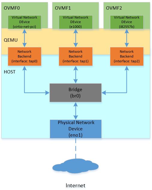 "QEMU and OVMF Network Topology")
The topology in the diagram creates three OVMF guests on one host system, and bridges all guests to the physical interface. Different host system has the different way to create the virtual interface for the network backend and setup the bridge connection for the traffic between OVMF and with the outside world. On Linux-based system, brctl and tunctl are recommended to you for such configuration. The example below is based on Ubuntu 16.04 LTS:
sudo apt-get install bridge-utils   /// Install brctl for the bridge creation.
sudo apt-get install uml-utilities  /// Install tunctl for the interface creation.

sudo brctl addbr br0                /// Create one bridge named as br0.
sudo brctl addif br0 eno1           /// Bridge eno1 (physical network) to br0.
sudo ifconfig eno1 up
sudo dhclient br0

sudo tunctl -t tap0 -u <username>   /// Create new interface named as tap0 for user.
sudo brctl addif br0 tap0           /// Bridge tap0 to br0.
sudo ifconfig tap0 up
...
You can also refer to the opensuse help page available at opensuse.org.
OVMF Debugging
Serial through file, console or remote TCP port can be used to trace the issue. OVMF also supports source level debug using the Intel® UEFI Development Kit Debugger Tool.
Verification Result
For OVMF, each virtual network device (e.g. e1000, virtio-net-pci, i82557b) can utilize an included iPXE stack (ROMFILE) and UEFI networking. iPXE is enabled by default. You can use the "romfile=" to disable the iPXE support so OVMF only utilizes the EDK II network stack.
qemu-system-x86_64 \
-global e1000.romfile="" \
-global virtio-net-pci.romfile="" \
-global i82557b.romfile=""
The full QEMU command to run OVMF1 using the topology above is shown as follows:
qemu-system-x86_64 \
  \
  -machine q35 \
  -m 8192 \
  -hda fat:/var/qemuDir \
  -pflash OVMF1.fd \
  -global e1000.romfile=""\
  -netdev tap,id=hostnet0,ifname=tap0,script=no,downscript=no \
  -device e1000,netdev=hostnet0
The table below lists the stack modules:
| Virtual Network Device | virtio (iPXE) | virtio (Native) | e1000 (iPXE) | e1000 (Native) | i82557b (iPXE) | i82557b (Native) |
|---|---|---|---|---|---|---|
| UNDI | efi-virtio.rom | VirtioPciDeviceDxe | efi-e1000.rom | E3522X2.EFI | efi-eepro100.rom | UndiRuntimeDxe |
| SNP | efi-virtio.rom | VirtioNet | efi-e1000.rom | SnpDxe | efi-eepro100.rom | SnpDxe |
| MNP | MnpDxe | MnpDxe | MnpDxe | MnpDxe | MnpDxe | MnpDxe |
| HTTP Boot | Pass | Pass | Pass | Pass | Pass | Failure |
NOTES
To run an i82557b native test, the UndiRuntimeDxe module must be included in the OVMF DSC/FDF files:
OptionRomPkg/UndiRuntimeDxe/UndiRuntimeDxe.inf
During i82557b native verification, you may encounter issues. For information on known issues, please refer to https://github.com/tianocore/edk2/issues/9587.
EDKII Network Scalability
The topology described above creates multiple OVMF guests to create a virtual cluster in one host. Another option creates multiple virtual network devices in one OVMF guest for verifying network scalability. The topology is shown as follows:
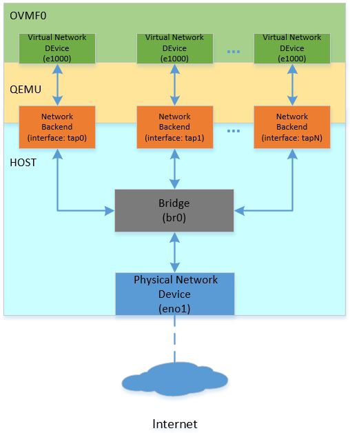 "QEMU OVMF Network Scalability")
The QEMU command to create multiple virtual network devices in one OVMF session is shown as follows:
qemu-system-x86_64 \
-netdev tap,id=hostnet0,ifname=tap0,script=no,downscript=no \
-netdev tap,id=hostnet1,ifname=tap1,script=no,downscript=no \
-netdev tap,id=hostnet2,ifname=tap2,script=no,downscript=no \
...
-netdev tap,id=hostnetX,ifname=tapX,script=no,downscript=no \
\
-device e1000,netdev=hostnet0 \
-device e1000,netdev=hostnet1 \
-device e1000,netdev=hostnet2 \
...
-device e1000,netdev=hostnetX \
NOTES
Due to a limit on PCI bus slots, there is a limit of less than 32 virtual network devices. There is a solution documented here: https://github.com/qemu/qemu/blob/master/docs/pcie.txt. PCI hierarchy is shown as follows:

This layout is reflected in the corresponding QEMU commands:
qemu-system-x86_64 \
-machine q35 \
\
-netdev tap,id=hostnet0,ifname=tap0,script=no,downscript=no \
-netdev tap,id=hostnet1,ifname=tap1,script=no,downscript=no \
-netdev tap,id=hostnet2,ifname=tap2,script=no,downscript=no \
...
-netdev tap,id=hostnetX,ifname=tapX,script=no,downscript=no \
\
-device i82801b11-bridge,id=dmi-pci-bridge \
-device pci-bridge,id=bridge-1,chassis_nr=1,bus=dmi-pci-bridge \
-device pci-bridge,id=bridge-2,chassis_nr=2,bus=dmi-pci-bridge \
-device pci-bridge,id=bridge-3,chassis_nr=3,bus=dmi-pci-bridge \
...
-device pci-bridge,id=bridge-X,chassis_nr=X,bus=dmi-pci-bridge \
\
-device e1000,netdev=hostnet0,bus=bridge-1,addr=0x1.0 \
-device e1000,netdev=hostnet1,bus=bridge-1,addr=0x2.0 \
-device e1000,netdev=hostnet2,bus=bridge-1,addr=0x3.0 \
...
-device e1000,netdev=hostnet30,bus=bridge-1,addr=0x1f.0 \
\
-device e1000,netdev=hostnet31,bus=bridge-2,addr=0x1.0 \
-device e1000,netdev=hostnet32,bus=bridge-2,addr=0x2.0 \
-device e1000,netdev=hostnet33,bus=bridge-2,addr=0x3.0 \
...
-device e1000,netdev=hostnet61,bus=bridge-2,addr=0x1f.0 \
\
...
The command above use Q35 for a larger IO space. In this PCI hierarchy, a DMI-PCI bridge is plugged into the root bridge, then PCI-PCI bridges are attached to the DMI-PCI bridge. The PCI-PCI bridges are used to attach all required PCI devices, so each PCI device has its own slot.
References
- EDKII Network Getting Started Guide: ../../platforms-packages/core-packages/networkpkg_getting_started_guide.md
- Networking within QEMU: https://wiki.qemu.org/Documentation/Networking
- QEMU Command: https://qemu.weilnetz.de/doc/qemu-doc.html
- OVMF Introduction: ../../platforms-packages/platform-ports/ovmf.md
- OvmfPkg README: https://github.com/tianocore/edk2/tree/master/OvmfPkg
- UEFI HTTP Boot with OVMF: https://en.opensuse.org/UEFI_HTTPBoot_with_OVMF
- Intel® UEFI Development Kit Debugger Tool: https://software.intel.com/en-us/articles/unified-extensible-firmware-interface
- PCI hierarchy: https://github.com/qemu/qemu/blob/master/docs/pcie.txt
- QEMU Virtual Network Device (Mailing Thread): https://lists.gnu.org/archive/html/qemu-devel/2017-07/msg01251.html
Enable UEFI PXE Boot in EDK II
PXE Boot is enabled by the EDK II network stack. If your platform does not have EDK II network stack built in yet, or you feel you miss any modules for enabling PXE boot, please refer to the “FEATURES ENABLING” section in the NetworkPkg Getting Started Guide.
NOTES: The platform must support the UUID detection by reading table-based SMBIOS. Please refer the section 5.2.1 of PXE v2.1 specification for more details.
Below is an example of Windows WDS failure when SMBIOS is absent, the prompt message says "error occurred while
communicating with the Windows Deployment Service server", but the failure is actually because of WDS client failed to
read platform information from SMBIOS table. The firmware will also print debug warning message like "PXE: Failed to
read system GUID from the smbios table!" in this situation.

Fmp Capsule Dependency Introduction
Introduction
There are situations where a platform may have separately updatable firmware components (e.g. motherboard, BMC, EC, etc.) and in some cases, there may be dependencies among them. For instance, FWx requires FWy to be at least version 2.0 to install. Today, we don’t have a way to express that in our infrastructure. Fmp capsule dependency attempts to add that capability through minor changes in the FMP capsule as well as a minor enhancement to FmpDxe driver and FmpDeviceLib. Capsule Dependency is an incremental change of FMP capsule (Signed Capsule) to evaluate the capsule’s version dependency requirement is satisfied or not before applying the update. Full feature is defined in UEFI Spec 2.8.
Implementation Details
Updated Capsule Update Work Flow
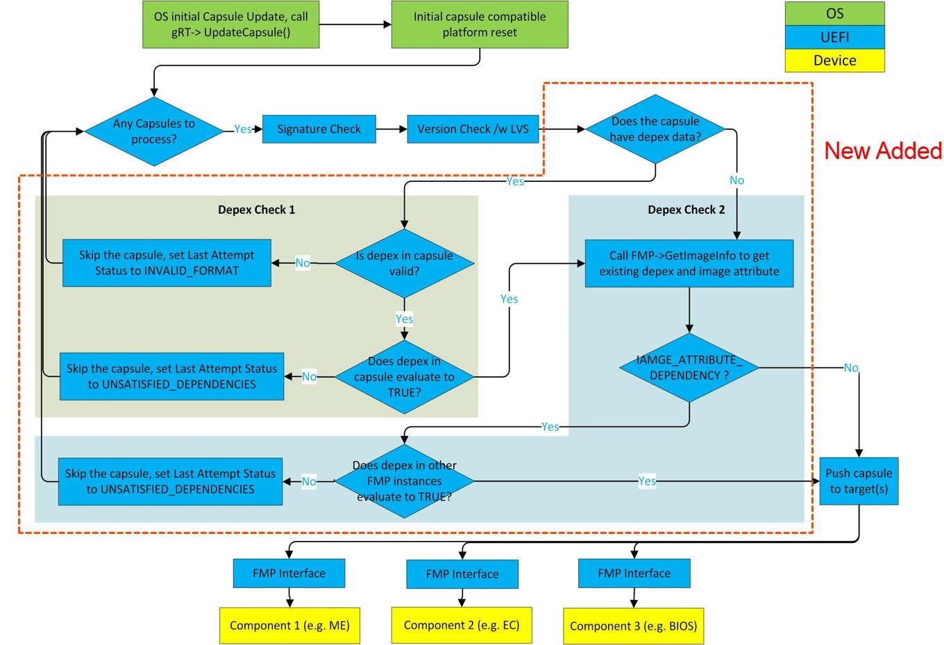
Last Attempt Status Extension
Extend ESRT status information to express if a capsule could not applied because its dependency could not be satisfied.
#define LAST_ATTEMPT_STATUS_ERROR_UNSATISFIED_DEPENDENCIES 0x00000008
Dependency Evaluation
Dependency evaluation process is a cross check between the capsule data and all existing FMP protocal instances in system.
- Check 1 : Validate platform exsiting Fmp Images' version to satisfy the dependency expression in capsule image.
- Check 2 : Validate the capsule image version to satify all the platform existing Fmp images' dependency expression.
FmpDeviceLib Extension
To support the Dependency Evaluation Check 2, Fmp device must have the capability to save its own dependency expression
and provide the dependency expression to Fmp DXE driver.
The parameter Image of FmpDeviceSetImage and FmpDeviceGetImage function is extended to contain the dependency
expression op-codes.
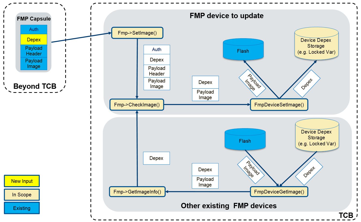
FmpDeviceSetImageis responsible for retrieving the dependency from the parameterImageand saving it to a protected storage.FmpDeviceGetImageis responsible for retrieving the dependency from the storage whereFmpDeviceSetImagesaves dependency and combining it with the Fmp Payload Image into one buffer which is returned to the caller. This dependency will be populated intoEFI_FIRMWARE_IMAGE_DESCRIPTORand used for Dependency Evaluation Check 2.FmpDeviceGetAttributesmust set the bitIMAGE_ATTRIBUTE_DEPENDENCYto indicate the Fmp device has dependency expression associcated with the Fmp image and supports Fmp Capsule Dependency feature.
Enable Fmp Capsule Dependency
How to enable capsule dependency feature for an Fmp Device
Please refer to the following sample code which uses EFI variable as the storage of Fmp dependency op-codes. Notice: The EFI variable must be locked before EndOfDxe. If no such implementation, only Dependency Evaluation Check 1 is supported.
1. FmpDeviceSetImage
EFI_STATUS
SaveFmpDependencyToStorage (
  IN  EFI_FIRMWARE_IMAGE_DEP  *Depex,
  IN  UINTN                   DepexSize
  )
{
  EFI_STATUS Status;

  if (DepexSize > 0 && Depex == NULL) {
    return EFI_INVALID_PARAMETER;
  }

  //
  // Save dependency op-codes to "FmpDepex" variable.
  //
  Status = gRT->SetVariable (
                  L"FmpDepex",
                  &gEfiCallerIdGuid,
                  EFI_VARIABLE_NON_VOLATILE | EFI_VARIABLE_BOOTSERVICE_ACCESS,
                  DepexSize,
                  (VOID *)Depex
                  );

  return Status;
}

EFI_STATUS
EFIAPI
FmpDeviceSetImage (
  IN  CONST VOID                                     *Image,
  IN  UINTN                                          ImageSize,
  IN  CONST VOID                                     *VendorCode,
  IN  EFI_FIRMWARE_MANAGEMENT_UPDATE_IMAGE_PROGRESS  Progress,
  IN  UINT32                                         CapsuleFwVersion,
  OUT CHAR16                                         **AbortReason
  )
{
  EFI_STATUS Status;
  UINTN      FmpDepexSize;
  UINTN      FmpPayloadImageSize;

  Status = FmpDeviceGetSize (&FmpPayloadImageSize);
  if (!EFI_ERROR (FmpPayloadImageSize) && ImageSize >= FmpPayloadImageSize) {
    //
    // Save dependency op-codes.
    //
    FmpDepexSize = ImageSize - FmpPayloadImageSize;
    Status = SaveFmpDependencyToStorage ((EFI_FIRMWARE_IMAGE_DEP *)Image, FmpDepexSize);
  }

  //
  // Continue to set image...
  //
}
2. FmpDeviceGetImage
EFI_FIRMWARE_IMAGE_DEP *
GetFmpDependencyFromStorage (
  OUT UINTN  *DepexSize
  )
{
  EFI_STATUS             Status;
  EFI_FIRMWARE_IMAGE_DEP *Depex;

  Depex = NULL;

  //
  // Get dependency from variable.
  //
  Status = GetVariable2 (
             L"FmpDepex",
             &gEfiCallerIdGuid,
             (VOID **) &Depex,
             DepexSize
             );

  return Depex;
}

EFI_STATUS
EFIAPI
FmpDeviceGetImage (
  IN OUT VOID   *Image,
  IN OUT UINTN  *ImageSize
  )
{
  EFI_FIRMWARE_IMAGE_DEP  *FmpDepex;
  UINTN                   FmpDepexSize;
  UINTN                   FmpPayloadImageSize;

  FmpDepex = GetFmpDependencyFromStorage (&FmpDepexSize);
  Status = FmpDeviceGetSize (&FmpPayloadImageSize);
  if (EFI_ERROR(Status)) {
    return EFI_ABORTED;
  }

  //
  // Make sure the buffer is big enough to hold the device image
  //
  if (*ImageSize < FmpPayloadImageSize + FmpDepexSize) {
    *ImageSize = FmpPayloadImageSize + FmpDepexSize;
    return EFI_BUFFER_TOO_SMALL;
  }

  *ImageSize = FmpPayloadImageSize + FmpDepexSize;
  //
  // Copy the FmpDepex to the buffer
  //
  CopyMem (Image, FmpDepex, FmpDepexSize);
  //
  // Continue to Copy the Fmp Payload image to the buffer...
  //

}
3. FmpDeviceGetAttributes
EFI_STATUS
EFIAPI
FmpDeviceGetAttributes (
  IN OUT UINT64  *Supported,
  IN OUT UINT64  *Setting
  )
{
  if (Supported == NULL || Setting == NULL) {
    return EFI_INVALID_PARAMETER;
  }
  //
  // Set IMAGE_ATTRIBUTE_DEPENDENCY to support capsule dependency.
  //
  *Supported = (IMAGE_ATTRIBUTE_IMAGE_UPDATABLE         |
                IMAGE_ATTRIBUTE_RESET_REQUIRED          |
                IMAGE_ATTRIBUTE_AUTHENTICATION_REQUIRED |
                IMAGE_ATTRIBUTE_DEPENDENCY              |
                IMAGE_ATTRIBUTE_IN_USE
                );
  *Setting   = (IMAGE_ATTRIBUTE_IMAGE_UPDATABLE         |
                IMAGE_ATTRIBUTE_RESET_REQUIRED          |
                IMAGE_ATTRIBUTE_AUTHENTICATION_REQUIRED |
                IMAGE_ATTRIBUTE_DEPENDENCY
                );

  return EFI_SUCCESS;
}
How to generate capsule with dependency feature
1. Encode
Capsule generate tool supports to encode capsule dependencies through '-j'
command with a JSON file, for example, to type following command in command prompt:
GenerateCapsule.py -e -j Example.json -o Example.cap
To add dependency feature, a "Dependencies" field in JSON file is required.
For example:
{
    "Payloads": [
        {
            "Guid": "d9ca4062-985c-4084-8445-e104691dd66b",
            "FwVersion": "1",
            "LowestSupportedVersion": "1",
            "MonotonicCount": "3",
            "HardwareInstance": "0",
            "UpdateImageIndex": "3",
            "Payload": "Payload1.bin",
            "OpenSslSignerPrivateCertFile": "TestCert.pem",
            "OpenSslOtherPublicCertFile": "TestSub.pub.pem",
            "OpenSslTrustedPublicCertFile": "TestRoot.pub.pem",
            "SigningToolPath": "C:\\OpenSSL",
            "Dependencies": "aa2fd162-59d1-4d73-bd2c-c6f9f353cdda >= 0x00000001 && 58e21611-44c0-44b7-bc43-488f45cd1e97 >= 0x00000002"
        },
        {
            "Guid": "1559cc9e-ee39-4ae7-aa1f-1b84570da3cf",
            "FwVersion": "1",
            "LowestSupportedVersion": "1",
            "MonotonicCount": "2",
            "HardwareInstance": "0",
            "UpdateImageIndex": "1",
            "Payload": "Payload2.bin",
            "SignToolPfxFile": "TestCert.pfx",
            "SigningToolPath": "C:\\SigningTools",
            "Dependencies": "TRUE"
        }
    ]
}
The value of “Dependencies” field should be C style infix notation expression, the relations between firmware opcodes
and expression operators/operands are listed below:
| Fimware Opcode | Infix notation expression | Dependency Binary |
|---|---|---|
| 0x00 (PUSH_GUID) | 03e6ed9c-afd6-4762-9de7-d78da3c7179e | {0x00, {0x03e6ed9c, 0xafd6, 0x4762, {0x9d, 0xe7, 0xd7, 0x8d, 0xa3, 0xc7, 0x17, 0x9e}} |
| 0x01 (PUSH_VERSION) | 0x00000001 | {0x01, 0x00000001} |
| 0x02 (DECLARE_VERSION_NAME) | DECLARE “Fmp Device 1” | {0x02, “Fmp Device 1”} |
| 0x03 (AND) | && | {0x03} |
| 0x04 (OR) | || | {0x04} |
| 0x05 (NOT) | ~ | {0x05} |
| 0x06 (TRUE) | TRUE | {0x06} |
| 0x07 (FALSE) | FALSE | {0x07} |
| 0x08 (EQ) | == | {0x08} |
| 0x09 (GT) | > | {0x09} |
| 0x0A (GTE) | >= | {0x0A} |
| 0x0B (LT) | < | {0x0B} |
| 0x0C (LTE) | <= | {0x0C} |
| 0x0D (END) | {0x0D} |
Noted that Opcode 0x0D (END) will automatically added after dependency encoding.
The precedence of infix notation expression operators is listed below from high to low, and it’s followed the C language operator precedence.
- () (brackets)
- ~ (NOT)
- >=, >, <=, < (GTE, GT, LTE, LT)
- == (EQ)
- && (OR)
- || (AND)
DECLARE "xxxx" is acting like comments, wherever it inserted in the infix notation expression, it will be converted as {DECLARE_VERSION_STRING, xxxx}.
All operators/operands in infix notation expression should split with spaces, except brackets.
Here are some example of dependency entry for all kinds of operators:
"Dependencies": "TRUE"
"Dependencies": "aa2fd162-59d1-4d73-bd2c-c6f9f353cdda >= 0x00000001 && 58e21611-44c0-44b7-bc43-488f45cd1e97 < 0x00000002"
"Dependencies": "aa2fd162-59d1-4d73-bd2c-c6f9f353cdda >= 0x00000001 || (58e21611-44c0-44b7-bc43-488f45cd1e97 < 0x00000002 && 567e834b-8310-4b33-ac76-967fbe51132c >= 0x00000003)"
"Dependencies": "aa2fd162-59d1-4d73-bd2c-c6f9f353cdda >= 0x00000001 DECLARE \"Fmp Device 1\""
2. Decode
Capsule dependency tool supports the dependencies decoding, for example, to type following command in command prompt:
GenerateCapsule.py -d Example.cap -o Test
All Decoded dependency expressions are written to Test.json for each payload.
3. Dump information
Dump info leverages Decode, for example, to type following command in command prompt:
GenerateCapsule.py --dump-info Example.cap
Here is an example for output dump information.
--------
EFI_FIRMWARE_IMAGE_AUTHENTICATION.MonotonicCount                = 0000000000000000
EFI_FIRMWARE_IMAGE_AUTHENTICATION.AuthInfo.Hdr.dwLength         = 00000B03
EFI_FIRMWARE_IMAGE_AUTHENTICATION.AuthInfo.Hdr.wRevision        = 0200
EFI_FIRMWARE_IMAGE_AUTHENTICATION.AuthInfo.Hdr.wCertificateType = 0EF1
EFI_FIRMWARE_IMAGE_AUTHENTICATION.AuthInfo.CertType             = 4AAFD29D-68DF-49EE-8AA9-347D375665A7
sizeof (EFI_FIRMWARE_IMAGE_AUTHENTICATION.AuthInfo.CertData)    = 00000AEB
sizeof (Payload)                                                = 00000053
--------
EFI_FIRMWARE_IMAGE_DEP.Dependencies = {
    00, 582DF9AB-E626-42A8-A11C-3FEA098FF3FA,
    01, 0x00000001,
    02, Fmp Device 1,
    0B,
    0D,
}
sizeof (EFI_FIRMWARE_IMAGE_DEP.Dependencies)    = 0000002E
sizeof (Payload)                                = 00000025
--------
FMP_PAYLOAD_HEADER.Signature              = 3153534D (MSS1)
FMP_PAYLOAD_HEADER.HeaderSize             = 00000010
How to test capsule dependency feature
For example, there are two Fmp devices in the system:
| Device | Version | GUID |
|---|---|---|
| Sample Device A | 0x01 | 79179BFD-704D-4C90-9E02-0AB8D968C18A |
| Sample Device B | 0x01 | 149DA854-7D19-4FAA-A91E-862EA1324BE6 |
Now Device A has an update to version 0x02 that requires the version of Device B to be at least 0x02. However B's version is 0x01 in the system, so this update must fail.
- Create Device A's capsule with the dependency on Device B:
## GenerateCapsule.py -e -j Av2.json -o Av2.cap
Example of A_v2.json:
{
    "Payloads": [
        {
            "Guid": "79179BFD-704D-4C90-9E02-0AB8D968C18A",
            "FwVersion": "2",
            "LowestSupportedVersion": "1",
            "MonotonicCount": "3",
            "HardwareInstance": "0",
            "UpdateImageIndex": "3",
            "Payload": "A_v2.bin",
            "OpenSslSignerPrivateCertFile": "TestCert.pem",
            "OpenSslOtherPublicCertFile": "TestSub.pub.pem",
            "OpenSslTrustedPublicCertFile": "TestRoot.pub.pem",
            "SigningToolPath": "C:\\OpenSSL",
            "Dependencies": "149DA854-7D19-4FAA-A91E-862EA1324BE6 >= 0x00000002"
        }
    ]
}
- Enter UEFI shell and update Device A by CapsuleApp.efi:
Shell> CapsuleApp.efi A_v2.cap
- After the update finishes, enter UEFI shell and check the update status. The expectation is that update fails with
UNSATISFIED_DEPENDENCIEerror status.
Shell> CapsuleApp -E
###### ########
## ESRT TABLE #
###### ########
EFI_SYSTEM_RESOURCE_TABLE:
FwResourceCount    - 0x2
FwResourceCountMax - 0x6
FwResourceVersion  - 0x1
EFI_SYSTEM_RESOURCE_ENTRY (0):
  FwClass                  - 79179BFD-704D-4C90-9E02-0AB8D968C18A
  FwType                   - 0x2 (DeviceFirmware)
  FwVersion                - 0x1
  LowestSupportedFwVersion - 0x1
  CapsuleFlags             - 0x0
  LastAttemptVersion       - 0x2
  LastAttemptStatus        - 0x8 (Error: Unsatisfied Dependencies)
If Device B's version is changed to 0x02, the update should success and the status would be:
  FwClass                  - 79179BFD-704D-4C90-9E02-0AB8D968C18A
  FwType                   - 0x2 (DeviceFirmware)
  FwVersion                - 0x2
  LowestSupportedFwVersion - 0x1
  CapsuleFlags             - 0x0
  LastAttemptVersion       - 0x2
  LastAttemptStatus        - 0x0 (Success)
Getting Started Writing MyHelloWorld.C
Example MyHelloWorld.c file:
/** @file
  Brief Description of UEFI MyHelloWorld
  Detailed Description of UEFI MyHelloWorld
  Copyright for UEFI MyHelloWorld
  License for UEFI MyHelloWorld
**/

#include <Uefi.h>
#include <Library/UefiApplicationEntryPoint.h>
#include <Library/UefiLib.h>

/**
  as the real entry point for the application.

  @param[in] ImageHandle    The firmware allocated handle for the EFI image.
  @param[in] SystemTable    A pointer to the EFI System Table.

  @retval EFI_SUCCESS       The entry point is executed successfully.
  @retval other             Some error occurs when executing this entry point.

**/
EFI_STATUS
EFIAPI
UefiMain (
  IN EFI_HANDLE        ImageHandle,
  IN EFI_SYSTEM_TABLE  *SystemTable
  )
{
  Print(L"Hello World \n");
  return EFI_SUCCESS;
}
Getting Started Writing MyHelloWOrld.Inf
Example of MyHelloWorld.inf
Please check for the latest version of the EDK II Specifications
Note: Copy and paste the GUID from : http://www.guidgen.com/ for the FILE_GUID in the example below
## @file
#  Brief Description of UEFI MyHelloWorld
#
#  Detailed Description of UEFI MyWizardDriver
#
#  Copyright for UEFI  MyHelloWorld
#
#  License for UEFI  MyHelloWorld
#
##

[Defines]
  INF_VERSION                    = 1.25
  BASE_NAME                      = MyHelloWorld
  FILE_GUID                      = #Copy and paste the GUID from http://www.guidgen.com/ here
  MODULE_TYPE                    = UEFI_APPLICATION
  VERSION_STRING                 = 1.0
  ENTRY_POINT                    = UefiMain
#
# The following information is for reference only and not required by the build tools.
#
#  VALID_ARCHITECTURES           = IA32 X64 IPF EBC Etc...
#

[Sources]
  MyHelloWorld.c

[Packages]
  MdePkg/MdePkg.dec

[LibraryClasses]
  UefiApplicationEntryPoint
  UefiLib

[Guids]

[Ppis]

[Protocols]

[FeaturePcd]

[Pcd]
Getting Started Writing Simple Application
How to Write a Simple EDK II UEFI Application
1) Create a Work Space Directory
e.g. mkdir edk2
2) Download the Edk II source and build tools
- Latest EDK II source from following Instructions on
Step by step instructions
- i.e. example >git clone https://github.com/tianocore/edk2.git
OR
3) Run the edksetup
Run *edksetup --nt32'' script from the command line prompt at the Work Space directory
- Windows Comand Prompt: C:\edk2> edksetup --nt32
- Linux like: bash$ .edksetup.sh BaseTools
4) Edit the file conf/target.txt
Modify TARGET_ARCH and TOOL_CHAIN_TAG as required.
- TOOL_CHAIN_TAG see:
- Windows Windows systems ToolChain Matrix
- Newer versions of LinuxUsing EDK II with Native GCC
- Older Linux distributions Unix-like systems
- Mac OS X Xcode
- TARGET_ARCH - Optional can also use
"-a"
on the BUILD command line
-
Both IA32 and X64 :
TARGET_ARCH = IA32 X64
-
Just X64 :
TARGET_ARCH = X64
-
On the commnad line overriding the target.txt: BUILD -a X64
-
5) Create a project
- Create a new directory. Can be a directory anywhere within the Work Space Directory (e.g. C:\edk2\MyHelloWorld or ~/src/edk2/MyHelloWorld)
- Create a .c file in the project directory (see example: MyHelloWorld.c)
- Create a .inf file in the project directory (see examle: MyHelloWorld.inf)
6) Build your UEFI Application
Build X64 UEFI Application
- Update an existing platform .DSC file with your project .inf file.
The following list some examples.
- Edit the DuetPkg/DuetPkgX64.dsc and add your new application to the the [Components] section and before the [BuildOptions] section. (e.g. MyHelloWorld/MyHelloWorld.inf )
- Invoke the Build
- At the command prompt > Build -a X64 -p DuetPkg/DuetPkgX64.dsc
- Final Output .efi file will be in the directory WorkSpace/Build/DuetPkg/DEBUG_$(TOOL_CHAIN_TAG)/X64
Build IA32 UEFI Application
- Since this is the default as per the target.txt Update the
Nt32Pkg/Nt32Pkg.dsc file.
-
Edit the Nt32Pkg/Nt32Pkg.dsc and add your new application to the the [Components] section and before the [BuildOptions] section. (e.g.
MyHelloWorld/MyHelloWorld.inf )
-
- Invoke the Build
- At the command prompt > Build
- Final Output .efi file will be in the directory WorkSpace/Build/NT32/DEBUG_$(TOOL_CHAIN_TAG)/IA32
- Test with Windows NT 32 emulation: command prompt > Build Run
Getting Started
See Getting Started with EDK II
How To Build OVMF
Building OVMF is fairly easy once you have installed a few pre-requisites. Please note, however, that building OVMF is not required if you are only interested in running OVMF, since we have provided pre-built binaries of OVMF.
Build Pre-requisites
- A edk2 build tree capable of building UEFI images
- If you are new to edk2 building then these getting started instructions may be helpful.
- An ASL compiler configured in your edk2 build tree
- Either the IASL compiler or the Microsoft ASL compiler can be used
- For Unix-like operating systems, IASL is the only option:
- Either the IASL compiler or the Microsoft ASL compiler can be used
- For newer Linux distributions, you should be able to install iasl via the distribution's package management system.
(This page may help.)
- Or, the Unix-like systems getting started guide includes details for installing IASL as
well.
- For Windows, you can download pre-built version of IASL compiler from http://www.acpica.org.
- For Windows, you can also download a pre-built version of the Microsoft ASL compiler from http://www.acpi.info.
Choosing which version of OVMF to build
First decide which version of OVMF you will build. You can choose to build the IA32 processor architecture and/or the X64 processor architecture. You should take into account the processor architectures which your toolchain is capable of building. Depending upon which you select, you should modify the ACTIVE_PLATFORM and TARGET_ARCH in Conf/target.txt.
| ACTIVE_PLATFORM | TARGET_ARCH | PEI code | DXE/UEFI code |
|---|---|---|---|
| OvmfPkg/OvmfPkgIa32.dsc | IA32 | IA32 | IA32 |
| OvmfPkg/OvmfPkgIa32X64.dsc | IA32 X64 | IA32 | X64 |
| OvmfPkg/OvmfPkgX64.dsc | X64 | X64 | X64 |
Example: Conf/target.txt values to build x64 UEFI image for OVMF using GCC5 compiler:
ACTIVE_PLATFORM = OvmfPkg/OvmfPkgX64.dsc TARGET_ARCH = X64 TOOL_CHAIN_TAG = GCC5
Once you have modified Conf/target.txt, you can run the build command.
bash$ build
If successful, you should now have a OVMF.Fd file under the Build sub-directory. The exact directory under the Build directory will depend upon the toolchain, dsc and processor architecture.
You can use OVMF.Fd to run OVMF.
See Also
https://github.com/tianocore/edk2/blob/master/OvmfPkg/README
Debugging EDK II using OvmfPkg with QEMU and Linux GDB
This example will show how to debug a simple application built with OvmfPkg then using the QEMU and GDB to debug the UEFI Application.
The following will use a UEFI_APPLICATION SampleApp.c as an example
- Add your UEFI application to the OvmfPkgIa32.dsc (using IA32 ) example:
SampleApp/SampleApp.infat the end of the[Components]section in the OvmfPkgIa32.dsc file. - Build OVMF for IA32 :
bash$ build -a IA32 -p OvmfPkg/OvmfPkgIa32.dsc -t GCC5 - Copy the output of SampleApp to the
hda-contentsdirectory similarly as shown in How-to-run-OVMF as a file system for QEMU. This will be in a similar directory to the following :/home/u-mypc/src/edk2/Build/OvmfIa32/DEBUG_GCC5/IA32
   SampleApp.efi
   SampleApp.debug
   SampleApp (Directory)
- Open a terminal(1) prompt in the
run-ovmfdirectory as shown in How-to-run-OVMF with the ovmf.fd file copied to bios.bin. - invoke QEMU with the following command:
bash$ qemu-system-i386 -s -pflash bios.bin -hda fat:rw:hda-contents -net none -debugcon file:debug.log -global isa-debugcon.iobase=0x402
- QEMU will load and boot to a UEFI Shell prompt
In the QEMU Window
Invoke your application.
Shell> fs0:
Fs0:\> SampleApp.efi
Open another terminal(2) prompt in the run-ovmf directory and check out the debug.log file.
bash$ cat debug.log
InstallProtocolInterface: 5B1B31A1-9562-11D2-8E3F-00A0C969723B 6F0F028
Loading driver at 0x00006AEE000 EntryPoint=0x00006AEE756 SampleApp.efi
InstallProtocolInterface: BC62157E-3E33-4FEC-9920-2D3B36D750DF 6F0FF10
See that Loading driver at 0x00006AEE000 is the memory location where your UEFI Application is loaded.
Keep this address in mind.
Additionally you might add a DEBUG statement to your application something like the following to get the entry point of
your code. :
DEBUG ((EFI_D_INFO, "My Entry point: 0x%08x\r\n", (CHAR16*)UefiMainMySampleApp ) );
Then when you bash$ cat debug.log you will also get the entry point for your application. In this example the entry
point is UefiMainMySampleApp.
My Entry point: 0x06AEE496
This is useful to double check your symbols are fixed up to the correct line numbers in your source file. Otherwise, the code you see in GDB may not be the code that is executing.
Invoking GDB
In the terminal(2) prompt
- Change to the directory where the
hda-contentsis located - Invoke GDB with the source layout window using
bash$ gdb --tui. At first there will be nothing in the source window. - Load your UEFI Application SampleApp.efi with the
filecommand.
(gdb) file SampleApp.efi
Reading symbols from SampleApp.efi...(no debugging symbols found)...done.
- Check where GDB has for .text and .data offsets with
info filescommand.
(gdb) info files
Symbols from "/home/u-mypc/run-ovmf/hda-contents/SampleApp.efi".
Local exec file:
        `/home/u-mypc/run-ovmf/hda-contents/SampleApp.efi',
        file type pei-i386.
        Entry point: 0x756
        0x00000240 - 0x000028c0 is .text
        0x000028c0 - 0x00002980 is .data
        0x00002980 - 0x00002b00 is .reloc
- We need to calculate our addresses for .text and .data section. Application is loaded under
0x00006AEE000(loading driver point - NOT Entrypoint) and we know text and data offsets.
 text = 0x00006AEE000  +  0x00000240 = 0x06AEE240
 data = 0x00006AEE000  +  0x00000240 + 0x000028c0 = 0x06AF0B00
- Unload the .efi file
(gdb) file
No executable file now.
No symbol file now.
- Load the symbols with the fixed up address using your applications output .debug file:
(gdb) add-symbol-file SampleApp.debug 0x06AEE240 -s .data 0x06AF0B00
add symbol table from file "SampleApp.debug" at

        .text_addr = 0x6aee240
        .data_addr = 0x6af0b00
(y or n) y
Reading symbols from SampleApp.debug...done.
- Set a break point. We have our entry point in the .inf file as:
UefiMainMySampleApp
(gdb) break UefiMainMySampleApp
Breakpoint 1 at 0x6aee496: file /home/u-uefi/src/edk2/SampleApp/SampleApp.c, line 40.
- Attach the GDB debugger to QEMU:
(gdb) target remote localhost:1234
Remote debugging using localhost:1234
0x07df6ba4 in ?? ()
- Continue in GDB
(gdb) c
Continuing.
In the QEMU Window Invoke your application again
Shell> fs0:
Fs0:\> SampleApp.efi
The GDB will hit your break point in your UEFI application's entry point and you can begin to debug with source code debugging.
You can set more break points in your code with : (gdb) break SampleApp.c:nn : where nn is the line of code in your
.c file
After setting a few break points use (gdb) c to continue executing in the QEMU window until the next break point is
hit. Then return to the GDB window to step, view local variables and continue debugging.
Use (gdb) info locals to view local variables
Debugging EDK II using OvmfPkg with QEMU and the Windows Debugger (WinDbg)
This example shows how to enable source debugging in QEMU with OvmfPkg using WinDbg.
Download the Required Applications
These instructions were tested on a Windows 10 host (19042) with QEMU 4.2.0, WinDbg from the Windows 8.1 SDK (6.3.9600.17298), and the Intel UDK Debugger Tool v1.5 for Windows.
WinDbg
- This version of the SDK can be downloaded from the SDK
archive
or via this direct link.
- For the purposes of source debugging, only the "Debugging Tools for Windows" needs to be selected during installation.

- These instructions will use the default installation location for WinDbg:
C:\Program Files (x86)\Windows Kits\8.1\Debuggers\x86- If you chose a different installation location, note it for future steps.
Intel UDK Debugger Tool
- Download the installer from Intel Software or via this direct link
- Begin installation
-
The default installation location will be used for the remaining instructions:
C:\Program Files (x86)\Intel\Intel(R) UEFI Development Kit Debugger Tool -
The installer will likely complain it cannot find a WinDbg installation as it looks in an older location.
-

- Provide the WinDbg location used during its installation.

- The installer will ask how you plan to debug. You can change this later but we can provide the settings we will use
now.
-
Debug Port Channel: TCP
-
Server: localhost
-
Port: 20716 (any available port can be used)
-
Once installation is complete, you can tweak your Intel UDK configuration file further from this location:
C:\Program Files (x86)\Intel\Intel(R) UEFI Development Kit Debugger Tool\SoftDebugger.ini -
For reference, by default it should contain the following contents:
-
   [Debug Port]
   Channel = TCP
   Port = 20716
   FlowControl = 1
   BaudRate = 115200
   Server = localhost

   [Target System]
   ; Debugger needs to know the target processor count in the initialization step.
   ;  Use a value larger enough.
   ProcessorCount = 16
   FlashRange        = 0xFF000000:0x1000000
   ;TemporaryRamRange = 0x80000000:0x80000
   NoAccessLimit     = 0x80000000

   [Debugger]
   Executable = C:\Program Files (x86)\Windows Kits\8.1\Debuggers\x86\windbg.exe
   Directory = C:\Program Files (x86)\Windows Kits\8.1\Debuggers\x86

   [Features]
   ; Have WinDbg to load the module symbols when the module is loaded in target,
   ;  which enables to set unresolved breakpoints.
   LoadModuleSymbol = 1

   TerminalRedirectionPort = 20715
-
You can customize this file further to suit your situation. The flash range for OVMF can be found in OvmfPkg/OvmfPkgDefines.fdf.inc.
- For example, for a 4MB image the flash range is currently defined as:
[0xFFC00000 : 0xFFFFFFFF]
- For example, for a 4MB image the flash range is currently defined as:
-
LoadModuleSymbolis an important setting to automatically have WinDbg load source symbols and to set unresolved breakpoints. Though it does appear to slow the session down when enabled. -
NoAccessLimitcan be set to 0. -
Note:
BaudRateandFlowControlsettings are used for serial channels and not required at this time though they are not harmful to leave in the file.
Building the Firmware
The firmware should be built with the SOURCE_DEBUG_ENABLE option set to TRUE and DEBUG_ON_SERIAL_PORT defined.
This
example builds a 64-bit OVMF image with Visual Studio 2019.
build -p OvmfPkg/OvmfPkgX64.dsc -a X64 -t VS2019 -D SOURCE_DEBUG_ENABLE=TRUE -D DEBUG_ON_SERIAL_PORT
If you'd like to disable optimizations, you can specify a NOOPT build target. For example:
build -p OvmfPkg/OvmfPkgX64.dsc -a X64 -t VS2019 -b NOOPT -D SOURCE_DEBUG_ENABLE=TRUE -D DEBUG_ON_SERIAL_PORT
Launching the Debug Session
You can launch QEMU and quickly run the "Start WinDbg with Intel UDK Debugger Tool" shortcut in the Start menu. However, the timing can be sensitive during initialization and you might get a connection timeout. It is recommended to launch the appropriate applications from a batch file to start the session reliably.
Here's a sample batch file that redirects the monitor and serial output to PuTTY:
start "Monitor" /B "C:\PuTTY\PUTTY.EXE" telnet://localhost:20717
start "Debugger" /B "C:\Program Files (x86)\Intel\Intel(R) UEFI Development Kit Debugger Tool\eXdi.exe" /LaunchWinDbg
start "Console" /B "C:\PuTTY\PUTTY.EXE" telnet://localhost:20715

start "QEMU" /B "C:\Program Files\qemu\qemu-system-x86_64.exe" ^
  -machine q35,smm=on ^
  -global ICH9-LPC.disable_s3=1 ^
  -drive if=pflash,format=raw,unit=0,file=C:\src\edk2\Build\OvmfX64\DEBUG_VS2019\FV\OVMF_CODE.fd,readonly=on ^
  -drive if=pflash,format=raw,unit=1,file=C:\src\edk2\Build\OvmfX64\DEBUG_VS2019\FV\OVMF_VARS.fd ^
  -monitor tcp:localhost:20717,server ^
  -serial tcp:localhost:20716,server
Similar example that uses Tera Term:
start "Monitor" /B "c:\Program Files (x86)\teraterm\ttermpro.exe" localhost:20717 /nossh
start "Debugger" /B "C:\Program Files (x86)\Intel\Intel(R) UEFI Development Kit Debugger Tool\eXdi.exe" /LaunchWinDbg
start "Console" /B "c:\Program Files (x86)\teraterm\ttermpro.exe" localhost:20715 /nossh

start "QEMU" /B "C:\Program Files\qemu\qemu-system-x86_64.exe" ^
  -machine q35,smm=on ^
  -global ICH9-LPC.disable_s3=1 ^
  -drive if=pflash,format=raw,unit=0,file=C:\src\edk2\Build\OvmfX64\DEBUG_VS2019\FV\OVMF_CODE.fd,readonly=on ^
  -drive if=pflash,format=raw,unit=1,file=C:\src\edk2\Build\OvmfX64\DEBUG_VS2019\FV\OVMF_VARS.fd ^
  -monitor tcp:localhost:20717,server ^
  -serial tcp:localhost:20716,server
Note that other customizations are possible for QEMU configuration this is just demonstrating an instance of configuration settings.
WinDbg Working Case Examples
This section briefly shows some samples of expected behavior when source level debug is working.
Multiple panels can be used to view system registers, the call stack, disassembly, source code, and the debugger command panel:

Locals can be viewed:

Types of locals are generally handled well:

More Information
There are many resources available online to help get started with using the Windows Debugger. These are just some starting points:
-
Intel UDK Debugger Tool Configuration and Setup Guide (a PDF in your installation directory).
This document also explains how to use some helpful Python extensions in WinDbg that can do things like dump the MTRR settings and perform firmware-specific operations such as dumping UEFI variables and the HOB list.
How to Develop With Containers
Because various EDKII project can have specific build tools and environment requirements it can be beneficial to use a container build environment for local development. TianoCore maintains container images for various Operating Systems and tool chains in the TianoCore Containers repository. These images contain the build tools and environment configurations to ensure a consistent and reproducible build between local development, CI, and pipeline platform builds.
If you are new to the concept of containers, more information can be found on the Docker website.
Setting up Docker
Some Docker software is not free and some uses of Docker may require a personal or Business subscription. Users should verify their use is licensed for their organization if necessary.
The existing TianoCore container images are created for use with Docker. On Linux, docker can be installed through the distributions package management application. For specific builds and for other operating systems, see the Docker install page.
Windows Docker Setup
It is strongly recommended to use the WSL 2 based engine when running Docker on Windows. This can be configured in the General settings in Docker Desktop. Generally, this provides better performance and overall design over the legacy. Details on this framework can be found in the Docker documentation.
Local Development
To use the build container images to develop locally, there are several configurations depending the developers preferences. This section details some tools and tips that make using containers for local development easier. This section is not comprehensive however and it is encouraged users experiment and consider contributing back any new useful configurations or tools to this documentation.
NOTE: If the code base is cloned in Windows, it is not advised to directly open this repository in a Linux dev container as the file system share between Windows and WSL 2 causes a very significant performance reduction. Instead, clone the repo in the WSL file system and map into the container or directly clone into the container.
For example:
- Install the WSL extension in VS code
- Launch a WSL 2 instance
- Clone the repository to a directory within the instance, not a mounted Windows drive
cdinto the cloned repository directory- Use the command
code .to start VS Code- VS Code should offer you the option 'Reopen in Container', click on it
Manually configuring the container
Some developers may wish to manually maintain their containers. This is useful for using editors that do not have native support for containers or the specific type of containers used.
First, select the image most appropriate from the TianoCore containers list or a custom image for a specific platform or project. This image can be pulled down from the docker command line.
docker pull ghcr.io/tianocore/containers/<image>:<tag>
After pulling the image, the image can be started. It is useful to map in the workspace from the host OS as this allows easy access to the code and build files from the host as well as the container.
docker run -i -v <local-code-directory>:<container-directory> --workdir=<container directory> --name=<name> ghcr.io/tianocore/containers/<image>:<tag>
After the container is existed, it can be resume by using the start command.
docker start -i <name>
When running in the container, the build instructions should be used as they normally would using the stuart commands.
Visual Studio Code
The Visual Studio Code Dev Container extension provides an easy and consistent way to use containers for local development. At the time of writing, this extension only supports Linux based containers. This extension provides a number of useful additions to the specified docker image on creation.
- Configures git credential manager to pipe in git credentials.
- Makes extensions available on code inside the container.
- Abstracts management of the container for seamless use in the editor.
For a shared docker image configuration, this can be configured by creating a .devcontainer file in the repository. Some useful configurations are details below.
| Configuration | Purpose |
|---|---|
| "privileged": true | This may be needed for access to KVM for QEMU acceleration. |
"forwardPorts": [####] | Can be used to forward debug or serial ports to the host OS. |
It may also be desireable to run initialization commands using the "postCreateCommand"
option. Specifically running git config --global --add safe.directory ${containerWorkspaceFolder}
may be required if mapping the repository into the container is expected.
And example of a devcontainer used for a QEMU platform repo is included below.
{
  "image": "ghcr.io/tianocore/containers/fedora-35-dev:latest",
  "postCreateCommand": "git config --global --add safe.directory ${containerWorkspaceFolder} && pip install --upgrade -r pip-requirements.txt",
  "forwardPorts": [5000],
  "privileged": true
}
Pipeline Builds
Both Azure pipelines and github workflows have native support for containers. Information on this can be found in the Azure Pipeline Documentation and the Github Workflow Documentation.
One important detail to note is that Azure pipelines will create a new user in the docker image during the pipeline. This user is used for all tasks and operations and so certain local user install locations may not be by default on the path.
Security Features Implemented in EDK II
EDK II implements a variety of platform security features. These are typically disabled or absent in open hardware platforms. While some platforms implement these with enable/disable build flags, other platforms require additional porting to enable security features.
Signed Firmware Updates
EDK II provides an implementation of capsule-based firmware update and firmware recovery features that can detect if a firmware update or a recovery image delivered via UEFI Capsule has been modified. It can also verify that the capsule applies to the platform that receives the capsule, and verifies that a firmware update does not violate any of the platforms's firmware rollback rules.
Please refer to Capsule Based Firmware Update and Firmware Recovery for detailed porting instructions.
Enabling UEFI Secure Boot
How to add Secure Boot to DSC and FDF
Note: Information for this section was written based on the UDK2010.SR1 release
Based on original variable driver in MdeModulePkg, variable driver in SecurityPkg provides authenticated variable service in UEFI 2.3.1 spec. Runtime crypto library, OpenSSL* library and variable driver are required to enable this feature.
1. Ensure OpensslLib* library instance is defined in [LibraryClasses] section of the platform DSC file:
- IntrinsicLib|CryptoPkg/Library/IntrinsicLib/IntrinsicLib.inf
- OpensslLib|CryptoPkg/Library/OpensslLib/OpensslLib.inf
2. Ensure BaseCryptLib library instances are defined in the platform DSC file:
- For PEI driver: BaseCryptLib|CryptoPkg/Library/BaseCryptLib/PeiCryptLib.inf
- For DXE driver: BaseCryptLib|CryptoPkg/Library/BaseCryptLib/BaseCryptLib.inf
- For RUNTIME driver: BaseCryptLib|CryptoPkg/Library/BaseCryptLib/RuntimeCryptLib.inf
- For SMM driver: BaseCryptLib|CryptoPkg/Library/BaseCryptLib/SmmCryptLib.inf
3. Ensure platform secure library is added in platform DSC. A NULL instance for PlatformSecureLib is provided as below. It can be replaced by a platform-specific library instance.
- SecurityPkg/Library/PlatformSecureLibNull/PlatformSecureLibNull.inf
4. Ensure library instance DxeImageVerificationLib is added to LibraryClasses section of module SecurityStubDxe in the platform DSC file:
MdeModulePkg/Universal/SecurityStubDxe/SecurityStubDxe.inf {
``
NULL|SecurityPkg/Library/DxeImageVerificationLib/DxeImageVerificationLib.inf
}
5. Add Authenticated Variable driver INF to [Component] section of the platform DSC file:
- SecurityPkg/VariableAuthenticated/Pei/VariablePei.inf
- SecurityPkg/VariableAuthenticated/RuntimeDxe/VariableRuntimeDxe.inf
- SecurityPkg/VariableAuthenticated/SecureBootConfigDxe/SecureBootConfigDxe.inf
6. Remove original variable driver INF from the platform FDF file:
- INF MdeModulePkg/Universal/Variable/Pei/VariablePei.inf
- INF MdeModulePkg/Universal/Variable/RuntimeDxe/VariableRuntimeDxe.inf
Add Authenticated Variable Driver INF to the platform FDF file:
- INF SecurityPkg/VariableAuthenticated/Pei/VariablePei.inf
- INF SecurityPkg/VariableAuthenticated/RuntimeDxe/VariableRuntimeDxe.inf
- INF SecurityPkg/VariableAuthenticated/SecureBootConfigDxe/SecureBootConfigDxe.inf
7. Update Variable GUID value of VARIABLE_STORE_HEADER in FDF file as:
#Signature: gEfiAuthenticatedVariableGuid =
# {0xaaf32c78, 0x947b, 0x439a, { 0xa1, 0x80, 0x2e, 0x14, 0x4e, 0xc3, 0x77, 0x92}}
0x78, 0x2c, 0xf3, 0xaa, 0x7b, 0x94, 0x9a, 0x43,
0xa1, 0x80, 0x2e, 0x14, 0x4e, 0xc3, 0x77, 0x92,
8. Set appropriate value of gEfiMdeModulePkgTokenSpaceGuid.PcdMaxVariableSize for security feature relative databases which uses EFI Variable as storage. Each database stores in a single variable, the maximum variable size is defined by PCD value of gEfiMdeModulePkgTokenSpaceGuid.PcdMaxVariableSize.
Database categories include:
- 1) PK database: only one entry for public key of PK plus header info.
- 2) KEK database: multi-entry for public key of KEK plus header info.
- 3) Authorized signature database: multi-entries for authorized signatures
and one entry for root X509 certificate, plus header info.
- 4) Forbidden signature database: multi-entries for forbidden signatures,
plus header info.
NOTICE: Typically the size of one X509 certificate is ~2k, which may exceed the default maximum variable size. Please adjust the value by PCD if needed.
9. Set a platform policy of image verification by PCDs. User can customize platform policy of image verification by PCD value before build a platform. In [PcdsFixedAtBuild] section of SecurityPkg.dec file, set the PCD value for each type of device accordingly.
For example, if the platform policy is defined as:
- 1) Trust all images from OptionROM.
- 2) Validate all images from removable devices and deny execute when security
violation occurs.
- 3) Validate all images from hard disk and query user to make decision when
security violation occurs.
In this case, the PCD value should be set as following:
- gEfiSecurityPkgTokenSpaceGuid.PcdOptionRomImageVerificationPolicy|0x00|UINT32|0x00000001
- gEfiSecurityPkgTokenSpaceGuid.PcdRemovableMediaImageVerificationPolicy|0x04|UINT32|0x00000002
- gEfiSecurityPkgTokenSpaceGuid.PcdFixedMediaImageVerificationPolicy|0x05|UINT32|0x00000003
10. Another authenticated variable service, named SMM authenticated variable, is also provided in SecurityPkg. SMM authenticated variable driver requires SMM FVB protocol which should be provided by platform driver and SMM FTW protocol which is already provided in MdeModulePkg. To enable SMM authenticated variable driver instead of non-SMM authenticated variable driver in SecurityPkg,
- SecurityPkg/VariableAuthenticated/RuntimeDxe/VariableRuntimeDxe.inf
should be replaced by following drivers in step 5 and 6:
- SecurityPkg/VariableAuthenticated/RuntimeDxe/VariableSmm.inf
- SecurityPkg/VariableAuthenticated/RuntimeDxe/VariableSmmRuntimeDxe.inf
Download PDF with examples
How to Sign UEFI Drivers & Applications .pdf
Enable User Identification
Note: Information for this section was written based on the UDK2010.SR1 release
In UID (User Identification) infrastructure, there are 4 UEFI drivers, one library instance and some platform specific changes in BDS. To enable UID feature:
1. Ensure the platform specific code had been integrated into the platform BDS. Identify () in User Manager Protocol should be invoked after console is ready and authentication device (e.g. Smart card) is connected.
2. Ensure OpensslLib* library instance is defined in [LibraryClasses] section of the platform DSC file:
     IntrinsicLib|CryptoPkg/Library/IntrinsicLib/IntrinsicLib.inf
     OpensslLib|CryptoPkg/Library/OpensslLib/OpensslLib.inf
3. Ensure BaseCryptLib library instances in each phase are defined in the platform DSC file:
     PEI phase:     BaseCryptLib|CryptoPkg/Library/BaseCryptLib/PeiCryptLib.inf
     DXE phase:     BaseCryptLib|CryptoPkg/Library/BaseCryptLib/BaseCryptLib.inf
     RUNTIME phase: BaseCryptLib|CryptoPkg/Library/BaseCryptLib/RuntimeCryptLib.inf
4. Add UID drivers to [Component] section of the platform DSC file:
- 1) UserIdentifyManagerDxe driver produces user manager protocol and loads
deferred image after user authentication.
-
SecurityPkg/UserIdentification/UserIdentifyManagerDxe/UserIdentifyManagerDxe.inf
-
2) PwdCredentialProviderDxe driver produces user credential protocol and
provides support for password credential.
-
SecurityPkg/UserIdentification/PwdCredentialProviderDxe/PwdCredentialProviderDxe.inf
-
3) UsbCredentialProviderDxe driver produces user credential protocol and
provides support for secure card credential.
-
SecurityPkg/UserIdentification/UsbCredentialProviderDxe/UsbCredentialProviderDxe.inf
-
4) UserProfileManagerDxe driver provide UI configure for user profiles in
UEFI HII Form Browser. It is an sample driver to configure basic user information. For advanced configuration, such as forbidding a user to load image from USB disk, it is not supported by this driver.
- SecurityPkg/UserIdentification/UserProfileManagerDxe/UserProfileManagerDxe.inf
5. Add library instance DxeDeferImageLoadLib to LibraryClasses section of module SecurityStubDxe in the platform DSC file. The library instance is invoked during loading an image into memory. The image loading could be deferred by the predefined policy in a PCD before user authentication, or be verified by current user access policy after user authentication.
MdeModulePkg/Universal/SecurityStubDxe/SecurityStubDxe.inf {
``
NULL|SecurityPkg/Library/DxeDeferImageLoadLib/DxeDeferImageLoadLib.inf
}
6. Add UID drivers to the platform FDF file:
- INF SecurityPkg/UserIdentification/UserIdentifyManagerDxe/UserIdentifyManagerDxe.inf
- INF SecurityPkg/UserIdentification/UserProfileManagerDxe/UserProfileManagerDxe.inf
- INF SecurityPkg/UserIdentification/PwdCredentialProviderDxe/PwdCredentialProviderDxe.inf
- INF SecurityPkg/UserIdentification/UsbCredentialProviderDxe/UsbCredentialProviderDxe.inf
7. Set the platform policy by PCDs.
User can customize platform policy by changing the default PCD value in SecurityPkg.dec before building a platform.
- 1) Deferred image load policy
The policy makes use of bitmasks for five predefined device types. If a bit is set, the image from the corresponding device will be trusted when loading. Image from any device is trusted by default.
- 2) USB token file name
USB credential provider will read a file as the credential information. The token file should be at the root directory of USB storage disk and its name is specified by PCD value. "Token.bin" is the default name of token file.
Enabling Trusted Compute Module (TPM)
Note: Information for this section was written based on the UDK2010.SR1 release
TCG measured boot consists of two PEI modules, four DXE drivers and three libraries and some platform specific changes. To enable TCG TPM feature:
1. Ensure the platform specific changes had been done.
- 1) Memory should be cleared if ClearMemory bit of variable MemoryOverwriteRequestControl
is set when doing memory initialization.
- 2) TcgPhysicalPresenceLibProcessRequest () from TCG physical presenceLib library
should be invoked to process pending TPM request in BDS when console is ready.
2. Ensure OpensslLib* library instance is defined in [LibraryClasses] section of the platform DSC file:
- IntrinsicLib|CryptoPkg/Library/IntrinsicLib/IntrinsicLib.inf
- OpensslLib|CryptoPkg/Library/OpensslLib/OpensslLib.inf
3. Ensure BaseCryptLib library instances in each phase are defined in the platfrom
DSC file:
- PEI phase: BaseCryptLib|CryptoPkg/Library/BaseCryptLib/PeiCryptLib.inf
- DXE phase: BaseCryptLib|CryptoPkg/Library/BaseCryptLib/BaseCryptLib.inf
4. Add library instance in the platform DSC file.
- 1) TPM common library
It provides some common function routines used by TCG drivers.
- SecurityPkg/Library/TpmCommLib/TpmCommLib.inf
- 2) TCG physical presence library
This library requires output device to display TPM state change request and input device to get user confirmation. Often it is invoked by BDS driver when console is ready.
- SecurityPkg/Library/DxeTcgPhysicalPresenceLib/DxeTcgPhysicalPresenceLib.inf
- 3) TPM measure boot library
The library instance provides measurement and log service for TPM measured boot. The instance is invoked during loading an image into memory. It should be added into LibraryClasses section of module SecurityStubDxe in the platform DSC file.
- SecurityPkg/Library/DxeTpmMeasureBootLib/DxeTpmMeasureBootLib.inf
MdeModulePkg/Universal/SecurityStubDxe/SecurityStubDxe.inf {
``
NULL|SecurityPkg/Library/DxeTpmMeasureBootLib/DxeTpmMeasureBootLib.inf
}
5. Add TPM drivers to [Component] section of the platform DSC file:
- 1) TCG TPM PEI driver initializes TPM device and measures the drivers in firmware.
- SecurityPkg/Tcg/TcgPei/TcgPei.inf
- 2) TCG TPM DXE driver produces EFI TCG protocol and measure the drivers which
are not from firmware.
- SecurityPkg/Tcg/TcgDxe/TcgDxe.inf
- 3) TCG SMM driver implements TPM definition block in ACPI table and registers
SMI callback functions for physical presence and MemoryClear to handle the requests from ACPI method.
- SecurityPkg/Tcg/TcgSmm/TcgSmm.inf
- 4) TCG UI driver provides a generic TCG configuration page in setup browser to
config TCG items.
- SecurityPkg/Tcg/TcgConfigDxe/TcgConfigDxe.inf
- 5) TCG physical presence PEI driver produces PEI_LOCK_PHYSICAL_PRESENCE_PPI to
indicate whether TPM need be locked in PEI phase or not. It can be replaced by a platform specific driver.
- SecurityPkg/Tcg/PhysicalPresencePei/PhysicalPresencePei.inf
- 6) TCG memory overwrite Control driver initilizes MemoryOverwriteRequestControl
variable. It will clear MOR_CLEAR_MEMORY_BIT bit if it is set.
- SecurityPkg/Tcg/MemoryOverwriteControl/TcgMor.inf
6. Add TPM drivers to the platform FDF file:
- INF SecurityPkg/Tcg/TcgPei/TcgPei.inf
- INF SecurityPkg/Tcg/TcgDxe/TcgDxe.inf
- INF SecurityPkg/Tcg/TcgSmm/TcgSmm.inf
- INF SecurityPkg/Tcg/TcgConfigDxe/TcgConfigDxe.inf
- INF SecurityPkg/Tcg/PhysicalPresencePei/PhysicalPresencePei.inf
- INF SecurityPkg/Tcg/MemoryOverwriteControl/TcgMor.inf
7. Set the platform policy by PCDs.
User can customize platform policy by changing the default PCD value in SecurityPkg.dec before building a platform.
- 1) TCG platform type
PCD PcdTpmPlatformClass specifies the type of TCG platform that contains TPM chip. Its value is set to 0 for PC client type by default. It should be set 1 for server.
-
gEfiSecurityPkgTokenSpaceGuid.PcdTpmPlatformClass|0|UINT8|0x00000006
-
2) Hide TPM device
The TPM device can be hided from firmware and OS. PcdHideTpm can dynamically control whether to hide the TPM if PcdHideTpmSupport is set TRUE.
- gEfiSecurityPkgTokenSpaceGuid.PcdHideTpmSupport|FALSE|BOOLEAN|0x00000007
Additional Notes
1. In this version of implementation of authenticated variable service, we support:
- 1) Public exponent of RSA key value is fixed as 0x10001.
- 2) Encoding schema of RSA is PKCS1.15.
2. Currently certificate time expiration checking is ignored. 3. No real-time CRL checking requirements for performance and size restriction in pre-boot environment. 4. Variable Size Limitation: KEK/X509/Signature Database store as authenticated variables in the system, with the database size limitation of max variable size of the platform. Users may choose to increase max variable size by PCD or to delete unused items when the database is full.
- * Other names and brands may be claimed as the property of others.
How To Run Ovmf
How to run OVMF with QEMU or KVM.
Pre-requisites
In order to run OVMF with QEMU, you must have QEMU version 0.9.1 or newer installed on your system.
To install on Debian/Ubuntu: sudo apt-get install qemu
Get a build of OVMF.fd
You can build OVMF based on the latest version of EDK II.
Pre-built images are available at https://www.kraxel.org/repos/
- These images are automatically built and track the latest OVMF code in the EDK II tree.
- Some of these builds include a seabios CSM and can boot non-UEFI “legacy” operating systems. Note: seabios is GPLv3 licensed)
- If your OS doesn’t work with RPM repositories, then you can manually download and decompress the RPM files under jenkins/edk2
Choose the correct processor architecture
Be sure to align the processor architecture for OVMF with the proper processor archtecture of QEMU.
For the IA32 build of OVMF, there is a little more choice, since the X64 processor is also compatible with IA32. Therefore, with the IA32 build of OVMF, you can use the following commands: qemu, qemu-system-i386 or qemu-system-x86_64.
For the X64 build of OVMF, however, you can only use the qemu-system-x86_64 command.
Setup a BIOS directory for OVMF QEMU
To use OVMF with QEMU, we utilize the -L QEMU command line parameter. This paramter takes a directory path, and QEMU will load the bios.bin from this directory.
Create a directory, and cd to the directory
For example:
bash$ mkdir ~/run-ovmf
bash$ cd ~/run-ovmf
Next, copy the OVMF.fd file into this directory, but rename OVMF.fd to bios.bin:
bash$ cp /path/to/ovmf/OVMF.fd bios.bin
Next, create a directory to use as a hard disk image for QEMU
(QEMU can turn the contents of a directory into a disk image 'on-the-fly'):
bash$ mkdir hda-contents
Run QEMU using OVMF
Here is a sample command:
bash$ qemu-system-x86_64 -L . -hda fat:hda-contents
If everything goes well, you should see a graphic logo, and the UEFI shell should start.
Note: iPXE is enabled on recent builds of QEMU, and may try to network boot if a valid network adapter is detected. To
disable iPXE, add -net none to the command line.
Optional: Point directly to UEFI firmware in edk2/Build directory
The path to the OVMF.fd image can be directly provided on the command line, rather than copying to another directory.
Example for debug image built using GCC5, with iPXE disabled:
qemu-system-x86_64 -L . --bios ~/src/edk2/Build/OvmfX64/DEBUG_GCC5/FV/OVMF.fd -net none
QEMU with -pflash
qemu-system-x86_64 -pflash bios.bin -hda fat:hda-contents -net none
Optional: QEMU with Read/Write Fat file system using a host directory
(Beware that QEMU makes the virtual FAT table once and host could get out of sync and QEMU might get confused)
qemu-system-x86_64 -pflash bios.bin -hda fat:rw:hda-contents -net none
Potential issues
KVM
Although the latest versions of OVMF should now support the latest versions of KVM, there is still a chance that you might encounter issues when using KVM. If OVMF fails to boot on QEMU (with KVM), try disabling KVM.
Introduction
The memory profile feature was introduced to help a developer analyze the hardware memory reservation in a UEFI firmware implementation. After enhanced, the memory profile feature can be also used for memory leak detection. The enhanced memory profile feature supports
- User can know which line of code calls gBS->AllocateXXX() / gSmst->SmmAllocateXXX().
- User can know which line of code calls AllocateXXX() API of MemoryAllocationLib that will call gBS->AllocateXXX() / gSmst->SmmAllocateXXX().
- User can know which line of code calls a specific API that will call gBS->AllocateXXX() / gSmst->SmmAllocateXXX() or AllocateXXX() API of MemoryAllocationLib.
- User can know total memory allocated by a specific line of code.
- User can configure to record single module only.
- User can configure when to enable recording.
- User can know RVA<->Symbol (Function, Source, Line).
This wiki page only focuses on how to enable memory leak detection with memory profile feature. The part I and II of white paper "A_Tour_Beyond_BIOS_Implementing_Profiling_in_EDKII"(https://github.com/tianocore-docs/Docs/raw/main/White_Papers/A_Tour_Beyond_BIOS_Implementing_Profiling_in_EDK_II.pdf) can be referred if you really want to know the inside working mechanism of memory profile feature.
PCDs, libraries and tools
PCDs
There are three PCDs PcdMemoryProfilePropertyMask, PcdMemoryProfileMemoryType and PcdMemoryProfileDriverPath defined in MdeModulePkg.dec(https://github.com/tianocore/edk2/blob/master/MdeModulePkg/MdeModulePkg.dec) to control the behaviors of memory profile feature.
## The mask is used to control memory profile behavior.
##  BIT0 - Enable UEFI memory profile.
##  BIT1 - Enable SMRAM profile.
##  BIT7 - Disable recording at the start.
## @Prompt Memory Profile Property.
## @Expression  0x80000002 | (gEfiMdeModulePkgTokenSpaceGuid.PcdMemoryProfilePropertyMask & 0x7C) == 0
gEfiMdeModulePkgTokenSpaceGuid.PcdMemoryProfilePropertyMask|0x0|UINT8|0x30001041

## This flag is to control which memory types of alloc info will be recorded by DxeCore & SmmCore.
## For SmmCore, only EfiRuntimeServicesCode and EfiRuntimeServicesData are valid.
#
## Below is bit mask for this PCD: (Order is same as UEFI spec)
## EfiReservedMemoryType 0x0001
## EfiLoaderCode 0x0002
## EfiLoaderData 0x0004
## EfiBootServicesCode 0x0008
## EfiBootServicesData 0x0010
## EfiRuntimeServicesCode 0x0020
## EfiRuntimeServicesData 0x0040
## EfiConventionalMemory 0x0080
## EfiUnusableMemory 0x0100
## EfiACPIReclaimMemory 0x0200
## EfiACPIMemoryNVS 0x0400
## EfiMemoryMappedIO 0x0800
## EfiMemoryMappedIOPortSpace 0x1000
## EfiPalCode 0x2000
## EfiPersistentMemory 0x4000
## OEM Reserved 0x4000000000000000
## OS Reserved 0x8000000000000000
#
## e.g. Reserved+ACPINvs+ACPIReclaim+RuntimeCode+RuntimeData are needed, 0x661 should be used.
#
## @Prompt Memory profile memory type.
gEfiMdeModulePkgTokenSpaceGuid.PcdMemoryProfileMemoryType|0x0|UINT64|0x30001042

## This PCD is to control which drivers need memory profile data.
## For example:
## One image only (Shell):
##     Header                    GUID
##     {0x04, 0x06, 0x14, 0x00,  0x83, 0xA5, 0x04, 0x7C, 0x3E, 0x9E, 0x1C, 0x4F, 0xAD, 0x65, 0xE0, 0x52, 0x68, 0xD0, 0xB4, 0xD1,
##      0x7F, 0xFF, 0x04, 0x00}
## Two or more images (Shell + WinNtSimpleFileSystem):
##     {0x04, 0x06, 0x14, 0x00,  0x83, 0xA5, 0x04, 0x7C, 0x3E, 0x9E, 0x1C, 0x4F, 0xAD, 0x65, 0xE0, 0x52, 0x68, 0xD0, 0xB4, 0xD1,
##      0x7F, 0x01, 0x04, 0x00,
##      0x04, 0x06, 0x14, 0x00,  0x8B, 0xE1, 0x25, 0x9C, 0xBA, 0x76, 0xDA, 0x43, 0xA1, 0x32, 0xDB, 0xB0, 0x99, 0x7C, 0xEF, 0xEF,
##      0x7F, 0xFF, 0x04, 0x00}
## @Prompt Memory profile driver path.
gEfiMdeModulePkgTokenSpaceGuid.PcdMemoryProfileDriverPath|{0x0}|VOID*|0x00001043
Libraries
After memory profile feature is enabled by configuring PCDs above, DxeCore and SmmCore will record alloc info for the code calls gBS->AllocateXXX() / gSmst->SmmAllocateXXX() by default. In order to record alloc info for the code calls AllocateXXX() API of MemoryAllocationLib or a specific API, MemoryProfileLib library class(https://github.com/tianocore/edk2/blob/master/MdeModulePkg/Include/Library/MemoryProfileLib.h) and instances are defined and implemented in MdeModulePkg.
- For DXE_CORE:
MemoryAllocationLib|MdeModulePkg/Library/DxeCoreMemoryAllocationLib/DxeCoreMemoryAllocationProfileLib.inf
MemoryProfileLib|MdeModulePkg/Library/DxeCoreMemoryAllocationLib/DxeCoreMemoryAllocationProfileLib.inf
- For DXE_DRIVER / DXE_RUNTIME_DRIVER / UEFI_DRIVER / UEFI_APPLICATION:
MemoryAllocationLib|MdeModulePkg/Library/UefiMemoryAllocationProfileLib/UefiMemoryAllocationProfileLib.inf
MemoryProfileLib|MdeModulePkg/Library/UefiMemoryAllocationProfileLib/UefiMemoryAllocationProfileLib.inf
- For SMM_CORE:
MemoryAllocationLib|MdeModulePkg/Library/PiSmmCoreMemoryAllocationLib/PiSmmCoreMemoryAllocationProfileLib.inf
MemoryProfileLib|MdeModulePkg/Library/PiSmmCoreMemoryAllocationLib/PiSmmCoreMemoryAllocationProfileLib.inf
- For DXE_SMM_DRIVER:
MemoryAllocationLib|MdeModulePkg/Library/SmmMemoryAllocationProfileLib/SmmMemoryAllocationProfileLib.inf
MemoryProfileLib|MdeModulePkg/Library/SmmMemoryAllocationProfileLib/SmmMemoryAllocationProfileLib.inf
After correct MemoryAllocationLib and MemoryProfileLib are linked, the alloc info for the code calls AllocateXXX() API of MemoryAllocationLib will be recorded. If you want to record the alloc info for the code calls a specific API, the specific API needs to be updated to call MemoryProfileLibRecord() API of MemoryProfileLib.
Tools
After memory profile feature is enabled and the system boots to SHELL, MemoryProfileInfo(https://github.com/tianocore/edk2/tree/master/MdeModulePkg/Application/MemoryProfileInfo) application in MdeModulePkg can be used to dump the profile information, then MemoryProfileSymbolGen.py(https://github.com/tianocore/edk2/blob/master/BaseTools/Scripts/MemoryProfileSymbolGen.py) can be used to convert RVA address to symbols for the profile information from MemoryProfileInfo application. In Linux, MemoryProfileSymbolGen.py will parse the debug information generated by the GCC compiler through “nm”. In Windows, MemoryProfileSymbolGen.py will parse the PDB information generated by the MSVC compiler through Microsoft Visual Studio “DIA SDK”.
How to enable
- Configure gEfiMdeModulePkgTokenSpaceGuid.PcdMemoryProfilePropertyMask in platform dsc to enable memory profiling for UEFI memory or SMRAM.
For example, only enable UEFI memory profiling.
[PcdsFixedAtBuild.common]
  gEfiMdeModulePkgTokenSpaceGuid.PcdMemoryProfilePropertyMask|0x1
- Configure gEfiMdeModulePkgTokenSpaceGuid.PcdMemoryProfileMemoryType in platform dsc to enable memory profiling for specific memory types.
For example, only enable EfiBootServicesData memory profiling.
[PcdsFixedAtBuild.common]
  gEfiMdeModulePkgTokenSpaceGuid.PcdMemoryProfileMemoryType|0x10
- Configure gEfiMdeModulePkgTokenSpaceGuid.PcdMemoryProfileDriverPath in platform dsc to only enable profiling for some specific drivers.
For example, only enable memory profiling for SHELL.
[PcdsFixedAtBuild.common]
gEfiMdeModulePkgTokenSpaceGuid.PcdMemoryProfileDriverPath|{0x04, 0x06, 0x14, 0x00, 0x83, 0xA5, 0x04, 0x7C, 0x3E, 0x9E,
0x1C, 0x4F, 0xAD, 0x65, 0xE0, 0x52, 0x68, 0xD0, 0xB4, 0xD1, 0x7F, 0xFF, 0x04, 0x00}
- Link correct MemoryAllocationLib and MemoryProfileLib library instances in platform dsc.
For example, link the library instances for SHELL.
[LibraryClasses.common.UEFI_APPLICATION]
  MemoryAllocationLib|MdeModulePkg/Library/UefiMemoryAllocationProfileLib/UefiMemoryAllocationProfileLib.inf
  MemoryProfileLib|MdeModulePkg/Library/UefiMemoryAllocationProfileLib/UefiMemoryAllocationProfileLib.inf
- [OPTIONAL] If you want to record the alloc info for the code calls a specific API, the specific API needs to be updated to call MemoryProfileLibRecord() API of MemoryProfileLib.
For example, you want to record the alloc info for the code calls StrnCatGrow(), the code change needed will like below.
diff --git a/ShellPkg/Library/UefiShellLib/UefiShellLib.c b/ShellPkg/Library/UefiShellLib/UefiShellLib.c
index 35a1a7169c8b..5356305dba21 100644
--- a/ShellPkg/Library/UefiShellLib/UefiShellLib.c
+++ b/ShellPkg/Library/UefiShellLib/UefiShellLib.c
@@ -18,6 +18,9 @@
 #include <Library/SortLib.h>
 #include <Library/BaseLib.h>

+#include <Library/MemoryProfileLib.h>
+#define ModuleProfileActionStrnCatGrow (MEMORY_PROFILE_ACTION_USER_DEFINED_MASK | MemoryProfileActionAllocatePool |
0x10000)
+
 #define FIND_XXXXX_FILE_BUFFER_SIZE (SIZE_OF_EFI_FILE_INFO + MAX_FILE_NAME_LEN)

 //
@@ -3264,11 +3267,31 @@ StrnCatGrow (
         NewSize += 2 * Count * sizeof(CHAR16);
       }
       *Destination = ReallocatePool(*CurrentSize, NewSize, *Destination);
+      if (*Destination != NULL) {
+        MemoryProfileLibRecord (
+          (PHYSICAL_ADDRESS) (UINTN) RETURN_ADDRESS(0),
+          ModuleProfileActionStrnCatGrow,
+          EfiBootServicesData,
+          *Destination,
+          NewSize,
+          (CHAR8 *) __FUNCTION__
+          );
+      }
       *CurrentSize = NewSize;
     }
   } else {
     NewSize = (Count+1)*sizeof(CHAR16);
     *Destination = AllocateZeroPool(NewSize);
+    if (*Destination != NULL) {
+      MemoryProfileLibRecord (
+        (PHYSICAL_ADDRESS) (UINTN) RETURN_ADDRESS(0),
+        ModuleProfileActionStrnCatGrow,
+        EfiBootServicesData,
+        *Destination,
+        NewSize,
+        (CHAR8 *) __FUNCTION__
+        );
+      }
   }

   //
diff --git a/ShellPkg/Library/UefiShellLib/UefiShellLib.inf b/ShellPkg/Library/UefiShellLib/UefiShellLib.inf
index 782649a7a034..b525b51140b8 100644
--- a/ShellPkg/Library/UefiShellLib/UefiShellLib.inf
+++ b/ShellPkg/Library/UefiShellLib/UefiShellLib.inf
@@ -48,6 +48,7 @@ [LibraryClasses]
   UefiLib
   HiiLib
   SortLib
+  MemoryProfileLib

 [Protocols]
   gEfiSimpleFileSystemProtocolGuid              ## SOMETIMES_CONSUMES
- [OPTIONAL, only for MSVC build] Configure build options.
-
Disable compiler optimization to make sure that RETURN_ADDRESS(0) can get the return address of the calling function correctly.
MSFT: *_*_*_CC_FLAGS = /Od -
If you want to build release image, debugging information needs to be enabled.
MSFT: RELEASE_*_*_DLINK_FLAGS = /DEBUG
MSFT: RELEASE_*_*_CC_FLAGS = /Zi
- Include MemoryProfileInfo application in platform dsc.
For example, for X64 build.
[Components.X64]
  MdeModulePkg/Application/MemoryProfileInfo/MemoryProfileInfo.inf
- Boot system to shell, run MemoryProfileInfo.efi to dump the profile information.
MemoryProfileInfo.efi >a MemoryProfileInfo1.txt
The summary data entries in MemoryProfileInfo1.txt will like below.
Summary Data:

Driver - Shell (Usage - 0x0000B606) (Pdb -
f:\git\edk2git\Build\NT32IA32\DEBUG_VS2015x86\IA32\ShellPkg\Application\Shell\Shell\DEBUG\Shell.pdb)
Caller List:
  Count            Size                   RVA              Action
==========  ==================     ================== (================================)
0x0000011A  0x000000000000B606 <== 0x00000000000152E8 (gBS->AllocatePool)
...
0x00000008  0x0000000000000154 <== 0x0000000000019691 (Lib:ReallocatePool)
0x00000001  0x0000000000000044 <== 0x000000000001D4EA (StrnCatGrow)
...
0x00000004  0x0000000000000062 <== 0x00000000000196C4 (Lib:AllocateZeroPool)
0x00000003  0x0000000000000036 <== 0x000000000001E0F9 (StrnCatGrow)
...
0x00000006  0x00000000000000A8 <== 0x0000000000007406 (StrnCatGrow)
...
0x00000001  0x000000000000002C <== 0x0000000000018372 (StrnCatGrow)
...
0x00000001  0x0000000000000068 <== 0x00000000000076F9 (StrnCatGrow)
- Copy MemoryProfileInfo1.txt to OS, run MemoryProfileSymbolGen.py to convert RVA address to symbols for the profile information.
Note: In Windows, MemoryProfileSymbolGen.py will parse the PDB information generated by the MSVC compiler through Microsoft Visual Studio “DIA SDK”, if you have no Dia2Dump.exe, you need to build out Dia2Dump.exe from source(for example, C:\Program Files (x86)\Microsoft Visual Studio 14.0\DIA SDK\Samples\DIA2Dump).
MemoryProfileSymbolGen.py -i MemoryProfileInfo1.txt -o MemoryProfileInfoSymbol1.txt
The summary data entries after converted in MemoryProfileInfoSymbol1.txt will like below.
Summary Data:

Driver - Shell (Usage - 0x0000B606) (Pdb -
f:\git\edk2git\Build\NT32IA32\DEBUG_VS2015x86\IA32\ShellPkg\Application\Shell\Shell\DEBUG\Shell.pdb)
Caller List:
  Count            Size                   RVA              Action
==========  ==================     ================== (================================)
0x0000011A 0x000000000000B606 <== 0x00000000000152E8 (gBS->AllocatePool) (InternalAllocatePool() -
f:\git\edk2git\edk2\mdemodulepkg\library\uefimemoryallocationprofilelib\memoryallocationlib.c:458)
...
0x00000008 0x0000000000000154 <== 0x0000000000019691 (Lib:ReallocatePool) (StrnCatGrow() -
f:\git\edk2git\edk2\shellpkg\library\uefishelllib\uefishelllib.c:3269)
0x00000001 0x0000000000000044 <== 0x000000000001D4EA (StrnCatGrow) (ShellCommandRegisterCommandName() -
f:\git\edk2git\edk2\shellpkg\library\uefishellcommandlib\uefishellcommandlib.c:571)
...
0x00000004 0x0000000000000062 <== 0x00000000000196C4 (Lib:AllocateZeroPool) (StrnCatGrow() -
f:\git\edk2git\edk2\shellpkg\library\uefishelllib\uefishelllib.c:3284)
0x00000003 0x0000000000000036 <== 0x000000000001E0F9 (StrnCatGrow) (ConvertEfiFileProtocolToShellHandle() -
f:\git\edk2git\edk2\shellpkg\library\uefishellcommandlib\uefishellcommandlib.c:1550)
...
0x00000006 0x00000000000000A8 <== 0x0000000000007406 (StrnCatGrow) (EfiShellGetMapFromDevicePath() -
f:\git\edk2git\edk2\shellpkg\application\shell\shellprotocol.c:322)
...
0x00000001 0x000000000000002C <== 0x0000000000018372 (StrnCatGrow) (ShellFindFilePath() -
f:\git\edk2git\edk2\shellpkg\library\uefishelllib\uefishelllib.c:1716)
...
0x00000001 0x0000000000000068 <== 0x00000000000076F9 (StrnCatGrow) (EfiShellGetFilePathFromDevicePath() -
f:\git\edk2git\edk2\shellpkg\application\shell\shellprotocol.c:484)
- Run some test, and then re-run step 8 and 9 to get MemoryProfileInfo2.txt and MemoryProfileInfoSymbol2.txt. Compare MemoryProfileInfoSymbol1.txt and MemoryProfileInfoSymbol2.txt to see if there is any difference. If MemoryProfileInfoSymbol2.txt shows more memory allocated, that means it is a potential memory leak.
NOTE: We call it is POTENTIAL memory leak because it might be legal in some cases. For example, a SHELL may choose to cache the recent command, or a variable. This must be investigated case by case.
MicroPython
MicroPython is a lean and efficient implementation of the Python 3 programming language that includes a small subset of the Python standard library and is optimised to run on microcontrollers and in constrained environments. -- micropython.org
A port of the MicroPython Interpreter for UEFI is available in edk2-staging: (MicroPythonPkg)
https://github.com/tianocore/edk2-staging/tree/MicroPythonTestFramework/MicroPythonPkg
This port was developed as a component of the MicroPython Test Framework for UEFI, designed for firmware unit testing and validation. It is also under evaluation to replace the existing Python 2.7 port for UEFI.
This project was publicly announced in March 2018 and added to the edk2-staging branch in August 2018.
Nate's Recommended Vscode Extensions And Settings
Visual Studio Code is currently my preferred text editor for working on EDK II code. However, making it a good environment for EDK II development work requires several extensions to be installed. My recommendations are below:
Recommended Extensions
- C/C++ Tools
- x86 and x86_64 Assembly Syntax Highlighting
- Edk2code
- Provides syntax highlighting for ASL, DEC, DSC, FDF, INF, UNI, VFR
- On Linux one must install cscope for this extension to work
sudo apt install cscopeor similar.
- Python Tools
- Code Spell Checker add-contextmenu-toggle-comment
- Bookmarks
- GitLens
- Git History
- Markdown All in One
Recommended Settings
I recommend you place these settings into your VSCode settings.json file:
{
    "files.associations": {
        "*.fdf": "edk2_fdf",
        "*.dsc": "edk2_dsc",
        "*.dec": "edk2_dec",
        "*.inf": "edk2_inf",
        "*.aslc": "c",
        "*.nasmb": "asm",
        "*.asm16": "asm"
    },
    "files.exclude": {
        "**/.git": true,
        "**/.svn": true,
        "**/.hg": true,
        "**/CVS": true,
        "**/.DS_Store": true,
        "**/Autogen.c": true,
        "Build/**": true,
    },
    "editor.renderWhitespace": "all",
    "files.trimTrailingWhitespace": true,
    "editor.tabSize": 2,
    "editor.rulers": [
        80,
        120
    ],
}
Obsolete Extensions
This functionality is now provided by Edk2code
New to Git
New to git? The git site has some great documentation:
EDK II git workflows
See EDK II Development Process
Some Potentially Dangerous Commands
Similar to using the dangerous rm -rf or del /s commands, there are some aspects of git usage you should be
careful with.
-
git reset --hard-
This command takes your current branch (head) and sets it to another revision. By default, it sets it to the last commit on the current branch.
-
Why it is potentially dangerous:
-
It will overwrite any change in files that you have not committed.
-
It can move your branch to somewhere else, and make you lose commits.
-
-
Ways to recover:
-
Uncommitted changes in files: NONE. There is no way to recover these lost changes!
-
Lost commits: There is a good chance you can recover the commits with the
git reflogcommand.
-
-
-
git clean-
This command deletes files in your local tree that are not tracked in your git repository.
-
Why it is potentially dangerous:
- It can delete files for new features that you have not yet added to git.
-
Ways to recover:
- NONE. There is no way to recover the deleted files!
-
Tip:
- Use the
--dry-runparameter to see what will be deleted.
- Use the
-
-
git merge-
This command joins together the histories of two branches.
-
For now, EDK II is choosing to maintain a linear history, and not use merges.
-
Why it is potentially dangerous:
- It is occasionally possible for git to choose the wrong action when auto-merging the two branches. Although rare, this can lead to some changes getting dropped in the latest tree.
-
Ways to recover:
-
If the merge has not be pushed upstream, there are a few ways to recover.
-
The best guaranteed way to fix things is to look through the history to find the tree version before your merge. (Helpful tools:
gitk,tig, orgit log --oneline --graph) -
Now, use
git reset --hard <good-version>- This will force your branch back to the state before the merge. Be sure to understand the dangers of
git reset --hardas documented above.
- This will force your branch back to the state before the merge. Be sure to understand the dangers of
-
You might also be able to simply use
git rebase origin/masterto remove the merge commit.
-
-
If the merged commit is pushed upstream, then unfortunately it will persist in history. This is not really a big deal, but just be sure that the merge worked correctly. If you find that changes were actually lost then add new commits to re-apply the changes.
-
-
-
git pull-
By default, the
git pullcommand is agit fetchfollowed by agit merge. Therefore it has the same concerns as thegit mergecommand documented above. -
Tip:
- You can also run
git config pull.rebase trueto set your edk2 tree up so thatgit pullwill be agit fetchfollowed by agit rebase(rather thangit merge)
- You can also run
-
-
git push -f-
This command 'force' pushes a branch. This potentially can force the remote branch to rewrite its history.
-
Note: The main edk2 tree is protected from force pushes, and you can setup your github branches to be similarly protected:
https://github.com/blog/2051-protected-branches-and-required-status-checks
-
Why it is potentially dangerous:
-
If you 'rewrite' the history of a tree, then people will be suspicious that bad changes have been snuck into the tree.
-
This is generally only considered bad for 'upstream' branches that many people are basing their work off of.
-
-
Ways to recover:
- You might be able to force push the old version back if you can find out its version.
-
It's sometimes okay to force push
-
For your personal development branches where no one is depending on the branch, it is okay to force push. In fact, most people will eventually find that force pushing is a good way to backup the currect state of their development work on a remote server.
-
It is also very common to make changes to the commit(s) on your branch based on code review feedback, amend the changes to the commits, and then force push to the branch to your fork which reflects the changes in its associated PR.
-
-
OBB Verification
OBB (Oem Boot Block) Verification is a common solution of maintaining the Chain-of-Trust in edk2 based firmware. It fills the gap between IBB (Initial Boot Block, verified by Root-of-Trust) and 3rd-party image (like OS loader, verified by Secure Boot). Following figure shows the point at which the OBB Verification complete the Chain-of-Trust in firmware.
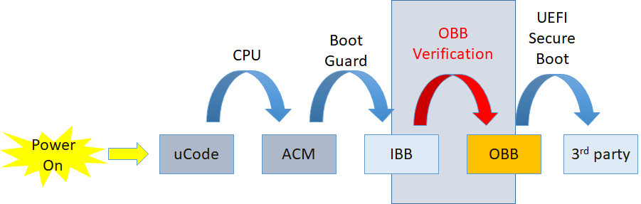
A typical IBB contains all firmware code/data running before physical memory discovered, and a typical OBB contains firmware code/data running in physical memory. In this solution, OBB must be in the form of FV (Firmware Volume). More than one FV are allowed.
The solution is implemented by module FvReportPei. It must be built into and running as part of IBB, which is verified by ACM (Authenticated Code Module). This PEIM is platform independent, which means it doesn't have any platform specific information hard-coded to complete its work. A new PPI, STORED_HASH_FV_PPI, is introduced for platform to pass information (such as FV address and size, OBB hash algorithm and value, etc.) of FVs to this PEIM.
A platform usually reports FVs to PEI Core and/or DXE Core via FV HOB or FV_INFO PPI for dispatching. If OBB Verification solution is employed in the platform, STORED_HASH_FV_PPI must be used instead to report those information, plus OBB hash information. FvReportPei will consume this PPI and verify those FVs, and then, if passed, report them to PEI Core and/or DXE Core accordingly (via FV HOB and/or FV_INFO PPI). Otherwise, FvReportPei will stop the boot process without passing the control back to PEI Core then no chance to OBB. Following figure shows a typical usage and boot flow with OBB verification based on Intel® Boot Guard.
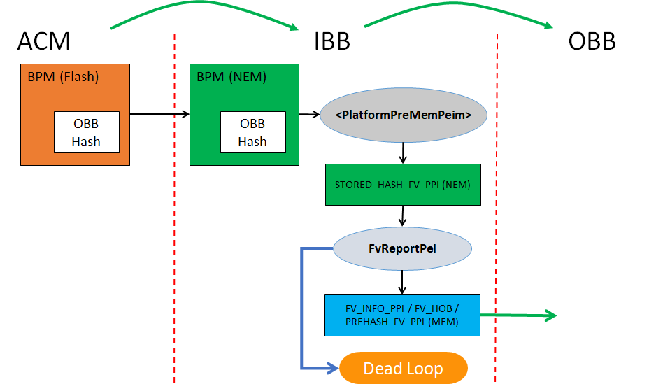
Status code, PcdStatusCodeFvVerificationPass or PcdStatusCodeFvVerificationFail, will be also reported upon verification pass or failure. The platform could register its own status code handler to intercept the result and does platform specific handling for the verification result.
To boost the boot performance, only hash algorithm (SHA256 or beyond) is currently used to verify the integrity of OBB. Other ways could be supported in the future, if requested. To save time in measurement boot, PREHASH_FV_PPI is also installed to report the digest of each FV along side the OBB FV verification. Then the TCG driver consuming the PPI doesn't have to re-calculate the hash for each of them, if the same hash algorithm is used for both OBB Verification and TPM measurement.
To meet above requirements, the OBB hash value must be calculated in following way
If OBB = FV1 + FV2 + FV3,
  FV1 -> FV1_Digest

  FV2 -> FV2_Digest

  FV3 -> FV3_Digest

  FV1_Digest + FV2_Digest + FV3_Digest -> OBB Hash
There's only one hash value allowed as OBB hash for one boot mode. As long as the FVs information is passed in the same order as in OBB hash calculating, FvReportPei is able to get the separate hash value for each FV as well as final OBB hash value, without repeated calculations.
OBB hash value and algorithm information must be stored in a way being able to be verified by Root-of-Trust such as BPM (Boot Policy Manifest) in Intel® Boot Guard. How to do it is a platform choice and varies per different hardware security technologies. Nevertheless, to avoid TOCTOU vulnerability, the OBB hash information (hash value, FV_INFO) as well as all OBB data itself must be stored and accessed in a more secure place, like memory, once they're verified. Both platform code and FvReportPei must make sure of it.
Different boot modes may have different OBB data (FVs) then different OBB hash for the sake of performance or other considerations. For example, normal boot mode may need to verify those FVs containing all drivers for PEI as well as DXE. But in S3 boot, only those drivers involved in S3 boot need verification. The platform developers can well organize those drivers into one FV and others into other FV(s), so that the firmware can skip verifying unwanted FVs to save boot time. How to store different OBB hash values for different boot modes is also a platform's choice. Platform must pass the different OBB hash values through STORED_HASH_FV_PPI with correct flags to instruct FvReportPei to verify the correct FVs against correct hash value.
Any tools or build process changes to support calculating OBB hash or generating OBB image are also platform's responsibility, not in the scope of this solution.
Porting An EDK Shell Extension
The goal of this section is to enable an engineer to easily take an EDK Shell Extension and move that to an EDK II UEFI Shell 2.0 application. This means primarily removing and replacing 3 types of references.
- EDK Shell protocols usage
- EDK Shell library usage
- EDK library usage and ‘standard’ EDK globals
The last of these three items is not always present whereas the first two are almost always present.
Eliminating the EDK Shell Protocols
There are 3 protocols directly associated with the EDK Shell. The protocols are:
- EFI_SHELL_ENVIRONMENT
- EFI_SHELL_ENVIRONMENT2
- EFI_SHELL_INTERFACE
The first protocol (EFI_SHELL_ENVIRONMENT) is a subset of the second one (EFI_SHELL_ENVIRONMENT2) and will not have a separate section.
Eliminating EFI_SHELL_ENVIRONMENT2
Execute
Use EFI_SHELL_PROTOCOL->Execute. This function does not exactly match, but has almost all of the same features. The major change is that the UEFI Shell Spec 2.0 does not allow for the running of internal shell commands through this function.
GetEnv
Use EFI_SHELL_PROTOCOL->GetEnv.
GetMap
This concept does not exist in the new shell. Use Shell Environment instead of shell maps.
AddCmd
This concept does not exist in the new shell. There is no way to dynamically add a command to the shell.
AddProt
This concept does not exist in the new shell. There is no way to dynamically add protocol information to the shell. You can look at the HandleParsingLib for some similar functionality.
GetProt
This concept does not exist in the new shell. There is no way to query protocol information in the shell. You can look at the HandleParsingLib for some similar functionality.
CurDir
Use EFI_SHELL_PROTOCOL-> GetCurDir.
FileMetaArg
Use EFI_SHELL_PROTOCOL-> OpenFileList
FreeFileList
Use EFI_SHELL_PROTOCOL-> FreeFileList
NewShell
This concept does not exist in the new shell. You can spawn a new shell via the Execute function.
BatchIsActive
Use EFI_SHELL_PROTOCOL-> BatchIsActive
FreeResources
This concept does not exist in the new shell.
EnablePageBreak
Use EFI_SHELL_PROTOCOL-> EnablePageBreak (Note that this is automatically controlled via ShellLib command line parsing functions)
DisablePageBreak
Use EFI_SHELL_PROTOCOL-> DisablePageBreak
GetPageBreak
Use EFI_SHELL_PROTOCOL-> GetPageBreak
SetKeyFilter
This concept is not part of the UEFI Shell. Key filtering must be done either manually or via the ShellLib with the functions ShellPromptForResponse and ShellPromptForResponseHii.
GetKeyFilter
This concept is not part of the UEFI Shell. Key filtering must be done either manually or via the ShellLib with the functions ShellPromptForResponse and ShellPromptForResponseHii.
GetExecutionBreak
This concept has changed in the UEFI Shell. There is a event that you can query EFI_SHELL_PROTOCOL-> ExecutionBreak. There is also a function in the ShellLib that helps (ShellGetExecutionBreakFlag).
IncrementShellNestingLevel
This concept does not exist in the new shell. The nesting level cannot be controlled outside the shell.
DecrementShellNestingLevel
This concept does not exist in the new shell. The nesting level cannot be controlled outside the shell.
IsRootShell
Use EFI_SHELL_PROTOCOL->IsRootShell.
CloseConsoleProxy
This concept does not exist in the new shell. The consoles cannot be controlled outside the shell.
HandleEnumerator (function group)
This concept does not exist in the new shell. There is no way to query protocol information in the shell. You can look at the HandleParsingLib for some similar functionality.
ProtocolInfoEnumerator (function group)
This concept does not exist in the new shell. There is no way to query protocol information in the shell. You can look at the HandleParsingLib for some similar functionality.
GetDeviceName
Use EFI_SHELL_PROTOCOL-> GetDeviceName
GetShellMode
This concept does not exist in the UEFI Shell. Shell support level and shell profiles present can be retrieved from environment variables.
NameToPath
Use EFI_SHELL_PROTOCOL-> GetDevicePathFromFilePath
GetFsName
Use EFI_SHELL_PROTOCOL-> GetMapFromDevicePath
FileMetaArgNoWildcard
Use EFI_SHELL_PROTOCOL-> OpenFileByName
DelDupFileArg
Use EFI_SHELL_PROTOCOL-> RemoveDupInFileList
GetFsDevicePath
Use EFI_SHELL_PROTOCOL-> GetDevicePathFromMap
Eliminating EFI_SHELL_INTERFACE
ImageHandle
Use ImageHandle from entry point. Most apps have gImageHandle global variable linked in from libraries.
Info
If you want EFI_LOADED_IMAGE_PROTOCOL you can get it manually.
Argv
Use EFI_SHELL_PARAMETERS_PROTOCOL->Argv
Argc
Use EFI_SHELL_PARAMETERS_PROTOCOL->Argv
RedirArgv
This concept does not exist in the new shell. Redirection is handled before applications are launched.
RedirArgc
This concept does not exist in the new shell. Redirection is handled before applications are launched.
StdIn
Use EFI_SHELL_PARAMETERS_PROTOCOL->StdIn
StdOut
Use EFI_SHELL_PARAMETERS_PROTOCOL->StdOut
StdErr
Use EFI_SHELL_PARAMETERS_PROTOCOL->StdErr
ArgInfo
This concept does not exist in the new shell.
EchoOn
This concept is not checkable in the new shell. The shell internally controls the echo state.
Eliminating Shell library functions
Eliminating common EfiShellLib functions
Due to the many different versions of the shell library and the many possible functions, only the most common functions will be covered here. If you find a function is not covered please report that as an enhancement request.
EFI_SHELL_APP_INIT, other initialization macro, or any initialization function
This should not be required. The EDKII ShellLib will automatically initialize itself. Only when building a shell internal command this is not true and the manual initialization must be called.
EFI_SHELL_STR_INIT, LibInitializeStrings, or any string function
If you need some strings put into HII it is expected that you will handle this yourself. Please refer to the HiiLib library class for doing this.
Math Functions
- such as LShiftU64, RShiftU64, MultU64x32, DivU64x32, etc...
All of these should be changed to EDK II library class BaseLib math functions.
GetBestLanguage
This function exists in the EDK II Library class UefiLib.
LibGetDriverName
This function can be called directly via COMPONENT_NAME_PROTOCOL.
Printing functions
PrintAt
This function is replaced by the EDK II ShellLib functions ShellPrintEx and ShellPrintHiiEx. You decide which to use based on whether the format string to be printed is contained in HII or not.
This function exists in the EDK II Library class UefiLib.
Output
This function is replaced by the Print() function.
SPrint
This function is in the process of being ported to EDK II.
PoolPrint
This function is in the process of being ported to EDK II.
PrintToken
This function is replaced by the EDK II ShellLib function ShellPrintHiiEx.
CatPrint
This function is replaced by the EDK II ShellLib function ShellPrintHiiEx.
Command Line Variable functions
The structure that you use for storing potential parameters is changed. Please see the new structure in the EDK II ShellLib.
GetNextArg, GetFirstArg, GetFirstFlag
These are all deprecated. The order of flags/arguments is not verified in the automatic parsing. For command lines where there are items passed in, but these items are not associated with a flag (for example, “command 0xff 0xaa” there is the EDK II ShellLib function ShellCommandLineGetRawValue.
LibCheckVarFreeVarList
Use the EDK II ShellLib function ShellCommandLineFreeVarList.
LibCheckVarGetFlag
This function is divided into 2 EDK II ShellLib functions. The first is ShellCommandLineGetFlag and is used to get whether a flag was present on the command line. The second is ShellCommandLineGetValue and is used to get the value that followed a flag on the command line (if there was a following value).
LibCheckVariables
Use the EDK II ShellLib function ShellCommandLineParseEx.
LibCheckRedirVariables
This concept does not exist in the new shell. Redirection is handled before applications are launched.
LibGetStdRedirFilename
This concept does not exist in the new shell. Redirection is handled before applications are launched.
LibGetErrRedirFilename
This concept does not exist in the new shell. Redirection is handled before applications are launched.
Eliminating EDK library usage and ‘standard’ EDK globals
Eliminating EDK library usage
All EDK library usage must be replaced.
Eliminating ‘standard’ EDK globals
RT
If your application is linked to the UefiRuntimeServicesTableLib then you will get a global called gRT. This is the replacement for RT.
BS
If your application is linked to the UefiBootServicesTableLib then you will get a global called gBS. This is the replacement for BS.
gSPP
If your application is linked to the ShellLib then you will get a global called gEfiShellParametersProtocol. This is the replacement for gSPP.
gSP
If your application is linked to the ShellLib then you will get a global called gEfiShellProtocol. This is the replacement for gSP.
Introduction
The SMI handler profile feature was introduced to help a developer analyzes which SMI handlers are exposed in an given boot.
The SMI handler includes:
- The root SMI handler or GUID SMI handler which is registered by SmmCore.
- The hardware child SMI handler which is registered by SmmChildDispatcher.
The SMI handler profile information includes:
- The function name of SMI Handler.
- The Name of the dispatcher the handler is registered with
- Source file name, line number.
- SMI context, such as SWSMI number.
This wiki page focuses on how to enable SMI handler profile feature.
PCDs, libraries and tools
PCDs
The PCD - PcdSmiHandlerProfilePropertyMask defined in MdeModulePkg.dec(https://github.com/tianocore/edk2/blob/master/MdeModulePkg/MdeModulePkg.dec) to control the behaviors of SMI handler profile feature.
## The mask is used to control SmiHandlerProfile behavior.
#  BIT0 - Enable SmiHandlerProfile.
# @Prompt SmiHandlerProfile Property.
# @Expression  0x80000002 | (gEfiMdeModulePkgTokenSpaceGuid.PcdSmiHandlerProfilePropertyMask & 0xFE) == 0
gEfiMdeModulePkgTokenSpaceGuid.PcdSmiHandlerProfilePropertyMask|0|UINT8|0x00000108
Libraries
After SMI handler profile feature is enabled by configuring PCDs above, SmmChildDispatcher driver should call SmiHandlerProfileRegisterHandler() to report SMI handler information. This API is defined in SmiHandlerProfileLib library class(https://github.com/tianocore/edk2/blob/master/MdePkg/Include/Library/SmiHandlerProfileLib.h).
SmiHandlerProfileLib|MdeModulePkg/Library/SmmSmiHandlerProfileLib/SmmSmiHandlerProfileLib.inf
If SMI handler profile feature is disabled, the SmmChildDispatcher driver can link NULL instance.
SmiHandlerProfileLib|MdePkg/Library/SmiHandlerProfileLibNull/SmiHandlerProfileLibNull.inf
Tools
After SMI handler profile feature is enabled and the system boots to SHELL, SmiHandlerProfileInfo(https://github.com/tianocore/edk2/tree/master/MdeModulePkg/Application/SmiHandlerProfileInfo) application in MdeModulePkg can be used to dump the information, then SmiHandlerProfileSymbolGen.py(https://github.com/tianocore/edk2/blob/master/BaseTools/Scripts/SmiHandlerProfileSymbolGen.py) can be used to convert RVA address to symbols and convert GUID name to a user readable string. In Linux, SmiHandlerProfileSymbolGen.py will parse the debug information generated by the GCC compiler through “nm”. In Windows, SmiHandlerProfileSymbolGen.py will parse the PDB information generated by the MSVC compiler through Microsoft Visual Studio “DIA SDK”.
How to enable
- Set PcdSmiHandlerProfilePropertyMask.
[PcdsFixedAtBuild]
gEfiMdeModulePkgTokenSpaceGuid.PcdSmiHandlerProfilePropertyMask|1
- Link correct SmiHandlerProfileLib instances in platform dsc.
[LibraryClasses]
SmiHandlerProfileLib|MdeModulePkg/Library/SmmSmiHandlerProfileLib/SmmSmiHandlerProfileLib.inf
- Update SmmChildDispatcher driver to report SMI handler via SmiHandlerProfileRegisterHandler().
diff --git a/QuarkSocPkg/QuarkNorthCluster/Smm/DxeSmm/QncSmmDispatcher/QNCSmmCore.c diff --git
a/QuarkSocPkg/QuarkNorthCluster/Smm/DxeSmm/QncSmmDispatcher/QNCSmmCore.c
b/QuarkSocPkg/QuarkNorthCluster/Smm/DxeSmm/QncSmmDispatcher/QNCSmmCore.c
index c2f75f8..0a8239c 100644
--- a/QuarkSocPkg/QuarkNorthCluster/Smm/DxeSmm/QncSmmDispatcher/QNCSmmCore.c
+++ b/QuarkSocPkg/QuarkNorthCluster/Smm/DxeSmm/QncSmmDispatcher/QNCSmmCore.c
@@ -2,7 +2,7 @@
This driver is responsible for the registration of child drivers
and the abstraction of the QNC SMI sources.
-Copyright (c) 2013-2016 Intel Corporation.
+Copyright (c) 2013-2017 Intel Corporation.
This program and the accompanying materials
are licensed and made available under the terms and conditions of the BSD License
@@ -23,6 +23,8 @@ WITHOUT WARRANTIES OR REPRESENTATIONS OF ANY KIND, EITHER EXPRESS OR IMPLIED.
#include "QNCSmm.h"
#include "QNCSmmHelpers.h"
+#include <Library/SmiHandlerProfileLib.h>
+
//
// /////////////////////////////////////////////////////////////////////////////
// MODULE / GLOBAL DATA
@@ -331,6 +333,7 @@ Returns:
DATABASE_RECORD *Record;
QNC_SMM_QUALIFIED_PROTOCOL *Qualified;
INTN Index;
+ UINTN ContextSize;
//
// Check for invalid parameter
@@ -363,6 +366,7 @@ Returns:
// Perform linked list housekeeping
//
Record->Signature = DATABASE_RECORD_SIGNATURE;
+ ContextSize = 0;
switch (Qualified->Type) {
//
@@ -383,6 +387,7 @@ Returns:
InsertTailList (&mPrivateData.CallbackDataBase, &Record->Link);
CopyMem (&Record->SrcDesc, &SX_SOURCE_DESC, sizeof (Record->SrcDesc));
+ ContextSize = sizeof(Record->ChildContext.Sx);
//
// use default clear source function
//
@@ -425,6 +430,7 @@ Returns:
InsertTailList (&mPrivateData.CallbackDataBase, &Record->Link);
CopyMem (&Record->SrcDesc, &SW_SOURCE_DESC, sizeof (Record->SrcDesc));
Record->BufferSize = sizeof (EFI_SMM_SW_REGISTER_CONTEXT);
+ ContextSize = sizeof(Record->ChildContext.Sw);
//
// use default clear source function
//
@@ -434,6 +440,7 @@ Returns:
InsertTailList (&mPrivateData.CallbackDataBase, &Record->Link);
CopyMem (&Record->SrcDesc, &GPI_SOURCE_DESC, sizeof (Record->SrcDesc));
+ ContextSize = sizeof(Record->ChildContext.Gpi);
//
// use default clear source function
//
@@ -450,6 +457,7 @@ Returns:
InsertTailList (&mPrivateData.CallbackDataBase, &Record->Link);
CopyMem (&Record->SrcDesc, &QNCN_SOURCE_DESCS[Record->ChildContext.QNCn.Type], sizeof (Record->SrcDesc));
Record->ClearSource = QNCSmmQNCnClearSource;
+ ContextSize = sizeof(Record->ChildContext.QNCn);
break;
case PeriodicTimerType:
@@ -462,6 +470,7 @@ Returns:
InsertTailList (&mPrivateData.CallbackDataBase, &Record->Link);
Record->BufferSize = sizeof (EFI_SMM_PERIODIC_TIMER_CONTEXT);
Record->ClearSource = QNCSmmPeriodicTimerClearSource;
+ ContextSize = sizeof(Record->ChildContext.PeriodicTimer);
break;
default:
@@ -488,6 +497,8 @@ Returns:
//
*DispatchHandle = (EFI_HANDLE) (&Record->Link);
+ SmiHandlerProfileRegisterHandler (Qualified->Guid, DispatchFunction, (UINTN)RETURN_ADDRESS (0), RegisterContext,
ContextSize);
+
return EFI_SUCCESS;
Error:
@@ -522,6 +533,8 @@ Returns:
DATABASE_RECORD *RecordToDelete;
DATABASE_RECORD *RecordInDb;
LIST_ENTRY *LinkInDb;
+ QNC_SMM_QUALIFIED_PROTOCOL *Qualified;
+ UINTN ContextSize;
if (DispatchHandle == NULL) {
return EFI_INVALID_PARAMETER;
@@ -552,7 +565,31 @@ Returns:
}
if (SafeToDisable) {
QNCSmmDisableSource( &RecordToDelete->SrcDesc );
-}
+ }
+
+ Qualified = QUALIFIED_PROTOCOL_FROM_GENERIC (This);
+ switch (Qualified->Type) {
+ case SxType:
+ ContextSize = sizeof(RecordToDelete->ChildContext.Sx);
+ break;
+ case SwType:
+ ContextSize = sizeof(RecordToDelete->ChildContext.Sw);
+ break;
+ case GpiType:
+ ContextSize = sizeof(RecordToDelete->ChildContext.Gpi);
+ break;
+ case QNCnType:
+ ContextSize = sizeof(RecordToDelete->ChildContext.QNCn);
+ break;
+ case PeriodicTimerType:
+ ContextSize = sizeof(RecordToDelete->ChildContext.PeriodicTimer);
+ break;
+ default:
+ ASSERT(FALSE);
+ ContextSize = 0;
+ break;
+ }
+ SmiHandlerProfileUnregisterHandler (Qualified->Guid, RecordToDelete->Callback, RecordToDelete->CallbackContext,
ContextSize);
FreePool (RecordToDelete);
diff --git a/QuarkSocPkg/QuarkNorthCluster/Smm/DxeSmm/QncSmmDispatcher/QNCSmmDispatcher.inf
b/QuarkSocPkg/QuarkNorthCluster/Smm/DxeSmm/QncSmmDispatcher/QNCSmmDispatcher.inf
index ed94825..23b806a 100644
--- a/QuarkSocPkg/QuarkNorthCluster/Smm/DxeSmm/QncSmmDispatcher/QNCSmmDispatcher.inf
+++ b/QuarkSocPkg/QuarkNorthCluster/Smm/DxeSmm/QncSmmDispatcher/QNCSmmDispatcher.inf
@@ -3,7 +3,7 @@
#
# This driver is responsible for the registration of child drivers
# and the abstraction of the ICH SMI sources.
-# Copyright (c) 2013-2015 Intel Corporation.
+# Copyright (c) 2013-2017 Intel Corporation.
#
# This program and the accompanying materials
# are licensed and made available under the terms and conditions of the BSD License
@@ -66,6 +66,7 @@
DevicePathLib
S3IoLib
QNCAccessLib
+ SmiHandlerProfileLib
[Protocols]
gEfiSmmCpuProtocolGuid # PROTOCOL ALWAYS_CONSUMED
- Include SmiHandlerProfileInfo application in platform dsc.
[Components]
MdeModulePkg/Application/SmiHandlerProfileInfo/SmiHandlerProfileInfo.inf
NOTE: Please make sure SmmCommunicationBufferDxe driver is include in both dsc and fdf.
[Components]
MdeModulePkg/Universal/SmmCommunicationBufferDxe/SmmCommunicationBufferDxe.inf
- Boot system to shell, run SmiHandlerProfileInfo.efi to dump the profile information.
SmiHandlerProfileInfo.efi >a SmiHandlerProfileInfoTemp.txt
The sample SmiHandlerProfileInfoTemp.txt is like below.
<?xml version="1.0" encoding="utf-8"?>
<SmiHandlerProfile>
<ImageDatabase>
<Image Base="0xFFEB000" EntryPoint="0xFFEC159" FvFile="E94F54CD-81EB-47ED-AEC3-856F5DC157A9" Name="PiSmmCore" Size="0x14000">
<Pdb>c:\home\edkiigit\Build\Quark\DEBUG_VS2015x86\IA32\MdeModulePkg\Core\PiSmmCore\PiSmmCore\DEBUG\PiSmmCore.pdb</Pdb>
</Image>
<Image Base="0xFFDF000" EntryPoint="0xFFE0139" FvFile="A6885402-D022-4B0E-A509-4711B90F2A39" Name="ReportStatusCodeRouterSmm" Size="0x6000">
<Pdb>c:\home\edkiigit\Build\Quark\DEBUG_VS2015x86\IA32\MdeModulePkg\Universal\ReportStatusCodeRouter\Smm\ReportStatusCodeRouterSmm\DEBUG\ReportStatusCodeRouterSmm.pdb</Pdb>
</Image>
......
</ImageDatabase>
<SmiHandlerDatabase>
<SmiHandlerCategory Name="RootSmi">
<SmiEntry>
<SmiHandler>
<Module>QNCSmmDispatcher</Module>
<Handler Address="0xFF2C89B">
<RVA>0x189B</RVA>
</Handler>
<Caller Address="0xFF2C442">
<RVA>0x1442</RVA>
</Caller>
</SmiHandler>
</SmiEntry>
</SmiHandlerCategory>
<SmiHandlerCategory Name="GuidSmi">
<SmiEntry HandlerType="ED32D533-99E6-4209-9CC0-2D72CDD998A7">
<SmiHandler>
<Module>VariableSmm</Module>
<Handler Address="0xFFCE6D8">
<RVA>0x16D8</RVA>
</Handler>
<Caller Address="0xFFCED12">
<RVA>0x1D12</RVA>
</Caller>
</SmiHandler>
</SmiEntry>
<SmiEntry HandlerType="2A3CFEBD-27E8-4D0A-8B79-D688C2A3E1C0">
<SmiHandler>
<Module>SmmLockBox</Module>
<Handler Address="0xFF4C527">
<RVA>0x1527</RVA>
</Handler>
<Caller Address="0xFF4C67C">
<RVA>0x167C</RVA>
</Caller>
</SmiHandler>
</SmiEntry>
......
</SmiHandlerCategory>
<SmiHandlerCategory Name="HardwareSmi">
<SmiEntry HandlerType="18A3C6DC-5EEA-48C8-A1C1-B53389F98999">
<SmiHandler SwSmi="0x1">
<Module>PiSmmCommunicationSmm</Module>
<Handler Address="0xFF1A2ED">
<RVA>0x12ED</RVA>
</Handler>
<Caller Address="0xFF1A489">
<RVA>0x1489</RVA>
</Caller>
</SmiHandler>
<SmiHandler SwSmi="0xA0">
<Module>AcpiSmmPlatform</Module>
<Handler Address="0xFF037B3">
<RVA>0x17B3</RVA>
</Handler>
<Caller Address="0xFF036CA">
<RVA>0x16CA</RVA>
</Caller>
</SmiHandler>
......
</SmiEntry>
<SmiEntry HandlerType="456D2859-A84B-4E47-A2EE-3276D886997D">
<SmiHandler SxPhase="SxEntry" SxType="SxS3">
<Module>AcpiSmmPlatform</Module>
<Handler Address="0xFF0383C">
<RVA>0x183C</RVA>
</Handler>
<Caller Address="0xFF03718">
<RVA>0x1718</RVA>
</Caller>
</SmiHandler>
......
</SmiEntry>
</SmiHandlerCategory>
</SmiHandlerDatabase>
</SmiHandlerProfile>
- Copy SmiHandlerProfileInfoTemp.txt to OS, run SmiHandlerProfileSymbolGen.py to convert RVA address to symbols and GUID to human readable string.
Note: In Windows, SmiHandlerProfileSymbolGen.py will parse the PDB information generated by the MSVC compiler through Microsoft Visual Studio “DIA SDK”, if you have no Dia2Dump.exe, you need to build out Dia2Dump.exe from source(for example, C:\Program Files (x86)\Microsoft Visual Studio 14.0\DIA SDK\Samples\DIA2Dump).
SmiHandlerProfileSymbolGen.py -i SmiHandlerProfileInfoTemp.txt -o SmiHandlerProfileInfoFinal.txt -g Guid.xref
The sample SmiHandlerProfileInfoFinal.txt is like below.
<?xml version="1.0" encoding="utf-8"?>
<SmiHandlerProfile>
<ImageDatabase>
<Image Base="0xFFEB000" EntryPoint="0xFFEC159" FvFile="E94F54CD-81EB-47ED-AEC3-856F5DC157A9" Name="PiSmmCore" Size="0x14000">
<Pdb>c:\home\edkiigit\Build\Quark\DEBUG_VS2015x86\IA32\MdeModulePkg\Core\PiSmmCore\PiSmmCore\DEBUG\PiSmmCore.pdb</Pdb>
</Image>
<Image Base="0xFFDF000" EntryPoint="0xFFE0139" FvFile="A6885402-D022-4B0E-A509-4711B90F2A39" Name="ReportStatusCodeRouterSmm" Size="0x6000">
<Pdb>c:\home\edkiigit\Build\Quark\DEBUG_VS2015x86\IA32\MdeModulePkg\Universal\ReportStatusCodeRouter\Smm\ReportStatusCodeRouterSmm\DEBUG\ReportStatusCodeRouterSmm.pdb</Pdb>
</Image>
......
</ImageDatabase>
<SmiHandlerDatabase>
<SmiHandlerCategory Name="RootSmi">
<SmiEntry>
<SmiHandler>
<Module>QNCSmmDispatcher</Module>
<Handler Address="0xFF2C89B">
<RVA>0x189B</RVA>
<Symbol>
<Function>QNCSmmCoreDispatcher</Function>
<SourceFile>c:\home\edkiigit\edk2\quarksocpkg\quarknorthcluster\smm\dxesmm\qncsmmdispatcher\qncsmmcore.c</SourceFile>
<LineNumber>611</LineNumber>
</Symbol>
</Handler>
<Caller Address="0xFF2C442">
<RVA>0x1442</RVA>
<Symbol>
<Function>InitializeQNCSmmDispatcher</Function>
<SourceFile>c:\home\edkiigit\edk2\quarksocpkg\quarknorthcluster\smm\dxesmm\qncsmmdispatcher\qncsmmcore.c</SourceFile>
<LineNumber>212</LineNumber>
</Symbol>
</Caller>
</SmiHandler>
</SmiEntry>
</SmiHandlerCategory>
<SmiHandlerCategory Name="GuidSmi">
<SmiEntry HandlerType="gEfiSmmVariableProtocolGuid">
<SmiHandler>
<Module>VariableSmm</Module>
<Handler Address="0xFFCE6D8">
<RVA>0x16D8</RVA>
<Symbol>
<Function>SmmVariableHandler</Function>
<SourceFile>c:\home\edkiigit\edk2\mdemodulepkg\universal\variable\runtimedxe\variablesmm.c</SourceFile>
<LineNumber>469</LineNumber>
</Symbol>
</Handler>
<Caller Address="0xFFCED12">
<RVA>0x1D12</RVA>
<Symbol>
<Function>VariableServiceInitialize</Function>
<SourceFile>c:\home\edkiigit\edk2\mdemodulepkg\universal\variable\runtimedxe\variablesmm.c</SourceFile>
<LineNumber>970</LineNumber>
</Symbol>
</Caller>
</SmiHandler>
</SmiEntry>
<SmiEntry HandlerType="gEfiSmmLockBoxCommunicationGuid">
<SmiHandler>
<Module>SmmLockBox</Module>
<Handler Address="0xFF4C527">
<RVA>0x1527</RVA>
<Symbol>
<Function>SmmLockBoxHandler</Function>
<SourceFile>c:\home\edkiigit\edk2\mdemodulepkg\universal\lockbox\smmlockbox\smmlockbox.c</SourceFile>
<LineNumber>266</LineNumber>
</Symbol>
</Handler>
<Caller Address="0xFF4C67C">
<RVA>0x167C</RVA>
<Symbol>
<Function>SmmLockBoxEntryPoint</Function>
<SourceFile>c:\home\edkiigit\edk2\mdemodulepkg\universal\lockbox\smmlockbox\smmlockbox.c</SourceFile>
<LineNumber>395</LineNumber>
</Symbol>
</Caller>
</SmiHandler>
</SmiEntry>
......
</SmiHandlerCategory>
<SmiHandlerCategory Name="HardwareSmi">
<SmiEntry HandlerType="gEfiSmmSwDispatch2ProtocolGuid">
<SmiHandler SwSmi="0x1">
<Module>PiSmmCommunicationSmm</Module>
<Handler Address="0xFF1A2ED">
<RVA>0x12ED</RVA>
<Symbol>
<Function>PiSmmCommunicationHandler</Function>
<SourceFile>c:\home\edkiigit\edk2\ueficpupkg\pismmcommunication\pismmcommunicationsmm.c</SourceFile>
<LineNumber>99</LineNumber>
</Symbol>
</Handler>
<Caller Address="0xFF1A489">
<RVA>0x1489</RVA>
<Symbol>
<Function>PiSmmCommunicationSmmEntryPoint</Function>
<SourceFile>c:\home\edkiigit\edk2\ueficpupkg\pismmcommunication\pismmcommunicationsmm.c</SourceFile>
<LineNumber>230</LineNumber>
</Symbol>
</Caller>
</SmiHandler>
<SmiHandler SwSmi="0xA0">
<Module>AcpiSmmPlatform</Module>
<Handler Address="0xFF037B3">
<RVA>0x17B3</RVA>
<Symbol>
<Function>EnableAcpiCallback</Function>
<SourceFile>c:\home\edkiigit\edk2\quarkplatformpkg\acpi\dxesmm\acpismm\acpismmplatform.c</SourceFile>
<LineNumber>623</LineNumber>
</Symbol>
</Handler>
<Caller Address="0xFF036CA">
<RVA>0x16CA</RVA>
<Symbol>
<Function>RegisterToDispatchDriver</Function>
<SourceFile>c:\home\edkiigit\edk2\quarkplatformpkg\acpi\dxesmm\acpismm\acpismmplatform.c</SourceFile>
<LineNumber>434</LineNumber>
</Symbol>
</Caller>
</SmiHandler>
......
</SmiEntry>
<SmiEntry HandlerType="gEfiSmmSxDispatch2ProtocolGuid">
<SmiHandler SxPhase="SxEntry" SxType="SxS3">
<Module>AcpiSmmPlatform</Module>
<Handler Address="0xFF0383C">
<RVA>0x183C</RVA>
<Symbol>
<Function>SxSleepEntryCallBack</Function>
<SourceFile>c:\home\edkiigit\edk2\quarkplatformpkg\acpi\dxesmm\acpismm\acpismmplatform.c</SourceFile>
<LineNumber>681</LineNumber>
</Symbol>
</Handler>
<Caller Address="0xFF03718">
<RVA>0x1718</RVA>
<Symbol>
<Function>RegisterToDispatchDriver</Function>
<SourceFile>c:\home\edkiigit\edk2\quarkplatformpkg\acpi\dxesmm\acpismm\acpismmplatform.c</SourceFile>
<LineNumber>459</LineNumber>
</Symbol>
</Caller>
</SmiHandler>
......
</SmiEntry>
</SmiHandlerCategory>
</SmiHandlerDatabase>
</SmiHandlerProfile>
Start Using UEFI
UEFI usage and support is rapidly growing in computing today. Our goal is to enable product manufacturers to create products that are shipped both supporting and using UEFI to boot the operating system. If you are interested in the EDK II implementation of UEFI please see Getting Started with EDK II.
However, if you are a technology enthusiast, then you may want to try out UEFI yourself. You should note that UEFI is focused on improving the firmware to OS interface from a code developer standpoint, and you may not notice much difference as a user once the operating system has started.
Warning
This page discusses methods to potentially install a UEFI compatible operating system on your computer. This can potentially lead to the loss of the data on your computer's hard drive. Please only proceed if you do not have valuable data on your computer's hard drive.
Tech Support Note
Our community is generally developer focused. We don't provide general technical support for usage of UEFI products. If you need official support for your UEFI product, then you should seek technical support from the product manufacturer.
UEFI compatible firmware
The first thing you will need in order to use UEFI is a compatible firmware.
UEFI compatible motherboard
You may have a UEFI compatible firmware in your motherboard. If your motherboard listed UEFI compatibility as a product feature, then this is good. If not, then you might still check the firmware (BIOS) setup, but your results may vary.
There are many possible ways that the motherboard product may enable UEFI support. Unfortunately, we can't document them all in this page. But, you might want to enter the firmware (BIOS) setup program for your product, and attempt to find a UEFI or EFI enabling question. Sometimes this can be found under the 'boot' menu of the firmware setup.
OVMF with QEMU or KVM
The OVMF project is part of our community tasks, and provides a UEFI compatible firmware for the QEMU and KVM virtual machine environments.
VirtualBox
VirtualBox (http://www.virtualbox.org) is a virtual machine environment. The more recent versions of VirtualBox can enable UEFI support in the VM settings under 'System' => 'Extended Features' => 'EFI support'.
UEFI compatible operating systems
Our community does not produce a UEFI compatible operating system. However, here we will list some operating systems which have some level of UEFI compatibility.
Ubuntu
Ubuntu provides UEFI bootable CD images for their 64-bit (X64) releases.
Structure Array Pcd
PCD can be declared as C Array in DEC file
- When PCD is declared in DEC file, VOID* will be replaced by C Array.
- C Array can be basic data type array, such as
UINT8[10] - C Array can be structure array, such as
TEST[20] - C Array can be flexible array, such as
TEST[]gTestPkgTokenSpaceGuid.PcdName|{0x00}|TEST[]|0x10000000 - C Array PCD value is VOID * type. C source code uses
PcdGetPtr(PcdName)API to get PCD value pointer, then convert it to C array, and access the element value. - If PCD is configured as Dynamic/DynamicEx PCD, C source code can use
PcdSetPtrS(PcdName, SizeOfBuffer, Buffer)API to update PCD value.
Structure or Array PCD value as C style initialization in DEC/DSC
- Globle C structure or array can be initialized with the value.
- If PCD is declared as C Structure or Array, its value can be specified with C style value.
For example:
gTestPkgTokenSpaceGuid.PcdName|{CODE({{0, {0, 0, 0, 0, 0, 0, 0}},{0, {0, 0, 0, 0, 0, 0, 0}},{0, {0, 0, 0, 0, 0, 0, 0}},{0, {0, 0, 0, 0, 0, 0, 0}},{0, {0, 0, 0, 0, 0, 0, 0}},{0, {0, 0, 0, 0, 0, 0, 0}},{0, {0, 0, 0, 0, 0, 0, 0}},{0, {0, 0, 0, 0, 0, 0, 0}},{0, {0, 0, 0, 0, 0, 0, 0}},{0, {0, 0, 0, 0, 0, 0, 0}},})}
Testing SMM with QEMU, KVM, and libvirt
This article describes an example setup for testing the edk2 SMM driver stack as it is built into OVMF, on QEMU/KVM, managed by libvirt. The setup uses hardware virtualization (KVM) and requires a Linux host machine.
We assume that the host machine is dedicated to the above kind of testing
(i.e., it is not a general purpose / interactive workstation or desktop
computer); we'll be using the root user. It's also assumed that the host is
in a protected internal network and not exposed on the public internet.
The examples below will use Fedora, for both host and (one) guest operating system; feel free to use any other Linux distribution that you like.
Hardware requirements
Please use an x86_64 machine with at least 4 logical processors (quad core with HT disabled, or dual core with HT enabled). The machine should have at least 8GB of RAM, and support Intel hardware virtualization (VT-x).
For now, EPT support is also required.
(In the longer term, SMM emulation in KVM should work without EPT. RHBZ#1348092 tracks this issue.)
Commands for verifying the host CPU features will be provided in the next section.
(There's no reason why an AMD host wouldn't be appropriate; this article assumes an Intel host only because such seem to be more widely available.)
Regarding disk space, a few hundred GB should be plenty. An SSD is strongly recommended.
Install the host operating system
Obtain the Live installation image for Fedora 26 Workstation (direct link), and boot it.
Before starting the installation, select Try Fedora on the GUI, open a terminal in the Live environment, and verify that the hardware requirements are satisfied. All of the following commands should return nonzero line counts (the actual counts should match the number of logical processors on your host):
grep -c -w vmx /proc/cpuinfo
grep -c -w ept /proc/cpuinfo
Furthermore, for performance reasons, a virtualization host is recommended (but
not required) where the following command outputs Y:
cat /sys/module/kvm_intel/parameters/unrestricted_guest
Proceed with the installation. For help, please refer to the Installation Guide.
In general, stick with the defaults. On the Configuration and Installation
Progress
screen, do not create a non-root user, only set the root password.
Perform an initial system update
Although this step is mentioned in the Installation Guide under Common Post-installation Tasks, it is worth mentioning here.
After booting the installed host OS, switch to a character console with
Ctrl+Alt+F2, log in as root, install any available updates, and reboot:
dnf --refresh upgrade
reboot
Remote access
After the installation and the initial system update, it is more convenient to access the virtualization host remotely.
-
Users on Linux desktops can run
virshandvirt-managerlocally, and implicitly connect to the remote libvirt daemon over SSH. -
For Windows users, it is recommended to set up a local X server, and an SSH client for forwarding X11 traffic. A succinct guide can be found here.
This is an optional step, not a requirement. However, without it, there's no easy way to bring the default virtual machine management GUI,
virt-manager, from the Linux virtualization host to one's familiar Windows productivity environment.
For both options above, the SSH daemon should be enabled and started on the
virtualization host. Log in as root on the GUI (if necessary, click the Not listed? label on the login screen, and enter root plus the appropriate
password). Open a terminal, and run the following commands:
systemctl enable sshd
systemctl start sshd
If the second option (X11 forwarding) is selected, then the following command is necessary as well:
dnf install xorg-x11-xauth
These are the last actions that, in the optimal case, should be performed with direct physical access to the virtualization host.
Install QEMU and libvirt
In this step no low-level system components are installed, therefore it's enough to log in to the virtualization host via SSH. Run the following commands:
dnf group install --with-optional virtualization
systemctl enable libvirtd
systemctl start libvirtd
systemctl enable virtlogd
systemctl start virtlogd
Enable nested virtualization
In this article, we have no use for nested virtualization, except as a somewhat
obscure test case (described below) for edk2's EFI_PEI_MP_SERVICES_PPI
implementation (which lives in UefiCpuPkg/CpuMpPei and
UefiCpuPkg/Library/MpInitLib). Given that multiprocessing is a primary
building block for the most important SMM driver in edk2
(UefiCpuPkg/PiSmmCpuDxeSmm), it makes sense to test multiprocessing with a
less demanding exercise as well.
Enabling nested virtualization in KVM, on the host, is ultimately one possible
trigger for OVMF to program the MSR_IA32_FEATURE_CONTROL register of all
VCPUs in parallel, exposing VT-x to the guest OS. (Please see the
RFE for details.) For
this, OVMF uses EFI_PEI_MP_SERVICES_PPI.
Permanently enable nested virtualization with the following commands:
sed --regexp-extended --in-place=.bak \
--expression='s,^#(options kvm_intel nested=1)$,\1,' \
/etc/modprobe.d/kvm.conf
rmmod kvm_intel
modprobe kvm_intel
Verify the setting -- the following command should print Y:
cat /sys/module/kvm_intel/parameters/nested
Install OVMF from source
-
Install build dependencies:
dnf install gcc-c++ nasm libuuid-devel acpica-tools -
Clone the upstream edk2 repository:
EDK2_SOURCE=$HOME/edk2 git clone https://github.com/tianocore/edk2.git $EDK2_SOURCE -
Download and embed OpenSSL into the edk2 source tree as instructed in the
$EDK2_SOURCE/CryptoPkg/Library/OpensslLib/OpenSSL-HOWTO.txtfile.At the time of this writing (2017-Jul-12), upstream edk2 still uses OpenSSL version
1.1.0e, although the OpenSSL project has released1.1.0fmeanwhile (on 2017-May-25). Therefore, the commands fromOpenSSL-HOWTO.txtcan currently be condensed like written below -- please double-check the sanctioned version inOpenSSL-HOWTO.txtfirst, and update theOPENSSL_VERassignment below as necessary:OPENSSL_VER=openssl-1.1.0e wget -q -O - http://www.openssl.org/source/${OPENSSL_VER}.tar.gz \ | tar -C $EDK2_SOURCE/CryptoPkg/Library/OpensslLib -x -z ln -s ${OPENSSL_VER} $EDK2_SOURCE/CryptoPkg/Library/OpensslLib/openssl -
Build OVMF:
cd $EDK2_SOURCE source edksetup.sh make -C "$EDK_TOOLS_PATH" build -a IA32 -a X64 -p OvmfPkg/OvmfPkgIa32X64.dsc \ -D SMM_REQUIRE -D SECURE_BOOT_ENABLE \ -D HTTP_BOOT_ENABLE -D TLS_ENABLE \ -t GCC5 \ -b NOOPT \ -n $(getconf _NPROCESSORS_ONLN) build -a IA32 -p OvmfPkg/OvmfPkgIa32.dsc \ -D SMM_REQUIRE -D SECURE_BOOT_ENABLE \ -D HTTP_BOOT_ENABLE -D TLS_ENABLE \ -t GCC5 \ -b NOOPT \ -n $(getconf _NPROCESSORS_ONLN)-
We build the
Ia32(32-bit PEI and DXE) andIa32X64(32-bit PEI, 64-bit DXE) OVMF platforms because they support ACPI S3 suspend/resume and SMM at the same time. S3 is a demanding use case for the SMM infrastructure, therefore we should enable this combination. -
The
X64build of OVMF does not support the same yet (UefiCpuPkg/Universal/Acpi/S3Resume2Peiforces OVMF to choose between S3 and SMM). Thankfully, the PEI bitness is entirely irrelevant to guest OSes, thus theIa32X64platform can be used identically, as far as OS-facing functionality is concerned. -
The
Ia32platform has more readily exposed instabilities in the edk2 SMM driver stack (as built into OVMF and run on QEMU), historically, than theIa32X64platform. Therefore it makes sense to buildIa32too. -
32-bit UEFI OSes are not covered in the current version of this article (2017-Jul-12).
-
-
Install OVMF (the split firmware binaries and variable store template):
OVMF_INSTALL=/opt/edk2/share/ovmf-smm mkdir -p -v $OVMF_INSTALL install -m 0644 -v \ ${EDK2_SOURCE}/Build/Ovmf3264/NOOPT_GCC5/FV/OVMF_CODE.fd \ ${OVMF_INSTALL}/OVMF_CODE.3264.fd install -m 0644 -v \ ${EDK2_SOURCE}/Build/Ovmf3264/NOOPT_GCC5/FV/OVMF_VARS.fd \ ${OVMF_INSTALL}/OVMF_VARS.fd install -m 0644 -v \ ${EDK2_SOURCE}/Build/OvmfIa32/NOOPT_GCC5/FV/OVMF_CODE.fd \ ${OVMF_INSTALL}/OVMF_CODE.32.fd chcon -v --reference=/usr/share/edk2/ovmf/OVMF_CODE.secboot.fd \ ${OVMF_INSTALL}/*.fd- In the last step, we copy the SELinux context from one of the Fedora-provided OVMF files to our manually built files, so that the latter too can be used with libvirt. (Fedora's own OVMF binaries are perfectly usable for end-users, it's just that the target audience of this article is people interested in edk2 development and analysis.)
Create disk images for the virtual machines
In this section, we create two disk images (one for a Fedora 26 guest, another for a Windows 10 guest). We also place a number of ISO images in the right place, so that we can install the guests from zero.
Fedora 26
-
Copy or move the image file
Fedora-Workstation-Live-x86_64-26-1.5.iso, which we also used for installing the virtualization host, to the directory/var/lib/libvirt/images/. -
Create an empty disk for the guest:
qemu-img create -f qcow2 \ -o compat=1.1 -o cluster_size=65536 \ -o preallocation=metadata -o lazy_refcounts=on \ /var/lib/libvirt/images/ovmf.fedora.q35.img 100GThe image file will have a nominal 100GB size, but it will only consume as much disk space on the host as necessary. In addition, whenever the
fstrimutility is executed in the guest, unused space will be returned to the host.
Windows 10
-
Download
en_windows_10_enterprise_2015_ltsb_n_x64_dvd_6848316.isofrom MSDN, and place it under/var/lib/libvirt/images/. -
Create an empty disk for the guest, similarly to the Fedora 26 command:
qemu-img create -f qcow2 \ -o compat=1.1 -o cluster_size=65536 \ -o preallocation=metadata -o lazy_refcounts=on \ /var/lib/libvirt/images/ovmf.win10.q35.img 100G -
When installing the Windows 10 guest, we'll need the VirtIO drivers. The following instructions have been distilled from the Fedora Project Wiki:
wget -O /etc/yum.repos.d/virtio-win.repo \ https://fedorapeople.org/groups/virt/virtio-win/virtio-win.repo dnf install virtio-winThe ISO image with the drivers becomes available through the
/usr/share/virtio-win/virtio-win.isosymlink.
Install the Fedora 26 guest
Libvirt domain definition (Fedora 26 guest)
Download the file ovmf.fedora.q35.template to the virtualization host, and define the guest from it:
virsh define ovmf.fedora.q35.template
After this step, the template file can be deleted.
Note that the template hard-codes a number of pathnames from the above
sections. If you changed any of those pathnames, please update the template
file accordingly, before running the virsh define command above. (Most of the
defined domain's characteristics can be edited later as well, with virsh edit
or virt-manager.)
This domain configuration can be used for both installing the guest and booting the installed guest.
Guest installation (Fedora 26 guest)
-
On the virtualization host, start
virt-manager.Windows users should preferably do this via SSH, with X11 forwarding; see under Remote Access above.
(Linux users should preferably run
virt-manageron their desktops instead, and connect to the remote libvirt daemon directly.) -
Select the guest name
ovmf.fedora.q35, and clickOpenin the menu bar.
-
In the
ovmf.fedora.q35guest's window, click the Play icon in the menu bar. This powers on the virtual machine. The TianoCore splash screen appears.
-
The Fedora Live environment is booted then. Proceed with the installation similarly to how the virtualization host was installed.
It may be necessary to select
View | Resize to VMin the menu bar.
Tests to perform in the installed guest (Fedora 26 guest)
Confirm "simple" multiprocessing during boot
This is the test that we enabled with nested virtualization.
-
Install the
rdmsrutility with the following command:dnf install msr-tools -
Query the Feature Control MSR on all VCPUs:
rdmsr -a 0x3a -
The output should be the same nonzero value (
0x5or0x100005) for all four VCPUs in the guest.
UEFI variable access test
-
Open a new terminal window, and run the following commands:
time taskset -c 0 efibootmgr time taskset -c 1 efibootmgrThey exercise the runtime UEFI variable services, running the services bound to VCPU-0 (BSP) and VCPU-1 (first AP) respectively. They trigger different parts of the SMM synchronization code in edk2.
-
The result for both commands should be the same, including closely matched (short) running times.
ACPI S3 suspend/resume loop
-
Under
Activities | Settings | Personal | Privacy | Screen Lock, setAutomatic Screen LocktoOff. -
Open a new terminal window, and input the following shell script:
X=0 while read -p "about to suspend"; do systemctl suspend echo -n "iteration=$((X++)) #VCPUs=" grep -c -i '^processor' /proc/cpuinfo done -
Whenever the prompt appears, hit
Enter. (HitControl-Cinstead ofEnterto terminate the test.) The guest should be suspended; its status in the Virt Manager overview window changes fromRunningtoSuspended. -
Hit
Enteragain, at the screen that is now black. The guest should resume without problems. Theiterationcounter should increase, while the number of VCPUs should remain 4. -
After a good number of iterations, abort the test, and repeat the UEFI variable access test.
Install the Windows 10 guest
Libvirt domain definition (Windows 10 guest)
Download the file ovmf.win10.q35.template to the virtualization host, and define the guest from it:
virsh define ovmf.win10.q35.template
After this step, the template file can be deleted.
If you changed any of the pathnames in the earlier sections, then the same warning applies as to the Fedora 26 guest.
Again, this domain configuration can be used for both installing the guest and booting the installed guest.
Guest installation (Windows 10 guest)
The same general comments apply as to the Fedora 26 guest. However, the Windows 10 install media does not contain VirtIO drivers. Therefore the Windows 10 domain configuration includes an additional CD-ROM drive, which is not on a VirtIO SCSI bus, but on a SATA bus.
The Windows 10 installer is booted off the VirtIO SCSI CD-ROM, using the UEFI
protocol stack (at the bottom of which is the OvmfPkg/VirtioScsiDxe driver in
this scenario). With the user's help, the installer can then fetch the native
VirtIO SCSI driver from the virtio-win SATA CD-ROM (using the built-in
Windows SATA driver).

After the final reboot during installation, the guest is usable, but its
display has no 2D acceleration (it uses the framebuffer inherited from OVMF's
EFI_GRAPHICS_OUTPUT_PROTOCOL). A few other VirtIO devices miss their drivers
too. Install them all in the Device Manager as follows (see again the Fedora
Project Wiki).
QXL Display Only Driver

VirtIO Network Card

VirtIO Balloon Device

VirtIO Serial Console

"HID Button over Interrupt Driver"
You may have noticed the stubborn yellow triangle in the above screenshots. This device is incorrectly recognized due to a typing error in Windows; please refer to RHBZ#1377155.
Tests to perform in the installed guest (Windows 10 guest)
ACPI S3 suspend/resume
-
Press
Ctrl+Alt+Delete, click on the Power Button icon in the lower right corner, then selectSleep. -
The status of the
ovmf.win10.q35guest should change toSuspendedin the Virt Manager overview. The guest screen goes dark. -
Hit
Enterin the (black) guest window, then move the mouse. The guest resumes, and the lock / Sign In screen is displayed.
UEFI application
UEFI application questions
Are there any guidelines for developing UEFI code in Runtime?
Currently there are only guidelines developing UEFI code for pre-boot. Link to the EDK II module writers guide: EDK_II Module Writer_s Guide_0_7.pdf
To develop UEFI code in runtime the applications the UEFI Specification defines the rules for writing runtime safe code along with the calling conventions and the rules that must be followed for UEFI runtime code to work correctly when the OS is running.
What would a UEFI application be allowed to do at runtime?
UEFI Applications may only execute in the pre-boot environment prior to ExitBootServices(). This means it is not possible for UEFI applications to be available at OS runtime. The only exception is a special class of UEFI application that is a UEFI OS Loader.
How do I view the sample program “HelloWorld”?
The “HelloWorld” is a sample application that is part of the MdeModulePkg in the edk2 directory https://github.com/tianocore/edk2 repository directory. There is both a HelloWorld.C for the source and an HelloWorld.INF file to build the module under EDK II.
A simple text editor can be used to view both of these files and make changes.
Is there a way to have applications start automatically?
If you are running from the shell then there are 2 ways.
- The shell will search for a script file called “startup.nsh” in any FAT file system that would get executed. Inside the script other UEFI applications could be invoked.
- The shell's command line can specify a UEFI application to run automatically.
Outside the shell there are different ways.
- The UEFI Specification also defines Boot Options. BootOption and BootOrder variables can be set to a UEFI Application can be auto executed on every boot.
The Boot Maintenance Manager provides menus to manually add a new Boot Option and re-order the active Boot Options. A UEFI Application can also be used to update the EFI Variables associated with Boot Options to add a new Boot Option to a platform. This would be the typical method used by an installer application. UEFI OS installers also use this method of updating the EFI Variables to add a newly installed operating system to the set of operating systems installed on a platform.
UEFI Capsule on Disk Introducation
Introduction
Firmware update, which aims to fixing system security vulnerabilities, supporting new devices as well as adding new features, is a common activity in modern computer service. UEFI also provides standard methodology to deliver update image to firmware Root of Trust for Update (RTU). The entire design follows NIST 800-193 which gives generic principles and mechanisms for firmware update. Design uses data object named Capsule to carry firmware update information including update image, update driver and signature. A typical firmware RTU only services in boot time. Therefore, delivering capsule to RTU requires system reset to give control back. UEFI spec describes 2 different ways in order to carry Capsule back to RTU – Capsule-in-RAM and Capsule-on-Disk. The following content covers detailed analysis towards these 2 features.
Related Concept
Boot trust regions is the similar concept of Trust Controlling Base (TCB) defined in TCG spec, which is considered as
the collection of system resources (hardware and software) that is responsible for maintaining the security policy of
the system.

Implementation Details
Capsule-in-RAM
Capsules are delivered from CapsuleUpdate() runtime service and saved in memory when passing control to RTU, which
requires memory content must be persistent across reset. After getting control, RTU module – CapsulePei is responsible
for reassembling capsule image and create capsule HOBs for coming standard capsule authentication and processing module
to consume.

Capsule-on-Disk
In Capsule-on-Disk case, capsules are firstly saved as file in EFI system partition on massive storage device which are identified by UEFI BOOT variables. To tradeoff platform requirement and security concerns, 2 different solutions are provided in order to deliver capsule to RTU – Solution A) Load Capsule-on-Disk image in memory and rely on capsule in RAM to deliver to RTU; Solution B) Keep Capsule-on-Disk images in external storage and relying on storage stack in PEI to load capsule file from disk, then pass to RTU.
Solution A(Recommended)
Solution A relies on Capsule-in-RAM. After Capsule-on-Disk images are detected, images are loaded to memory and passed
as Capsule in RAM. Platform must provide memory persistent reset flow to give control back to RTU while content intact.

Solution B
Comparing with solution A, Solution B keeps Capsule images in massive storage devices which are naturally persistent
during any types of reset. It eliminates the memory persistent reset requirement in Solution A. After firmware gets
control after reset, it reuses PEI storage stack to load capsule image in memory and pass to later standard capsule
authentication and processing module.

Security Analysis
The way to deliver capsule data and corresponding parsing logic is very sensitive to platform security as flash is usually open to write at that moment. If not properly handled, flash could be tampered by adversaries, causing escalate of privilege, permeant deny of service etc. The design in each solution is different, while security objective, threats and mitigation plan of each solution also varies a lot.
- Capsule-in-RAM stores capsules in memory which is described a scatter list. CapsulePei inside BIOS TCB must carefully validate the scatter list before further processing. During validation, there is only memory access which is inside TCB.
- Capsule-on-Disk solution A) reuses Capsule-in-RAM security plan without adding extra attack surface and external input.
- Capsule-on-Disk solution B) use an intermediate temp relocation file to exclude standard partition and file system driver from TCB. The temp file and indicator are considered to be new attack surface. Reading temp file though PEI storage stack is also considered risk to external HW adversary such as DMA attack. Platform is highly recommended to enable VT-D (IOMMU) if massive storage device requires use of DMA to read temp file
Platform Consideration
Platform enabling must take security analysis into seriously consideration when enabling firmware update feature. The attack surface of Capsule-in-RAM is considered relatively simple and small. It is highly recommended to be enabled if memory persistent reset is available and all update critical device can function normally under this reset on this platform. If platform also want to support Capsule on Disk, it is highly recommended to choose Solution A because it doesn’t introduce any new attack surface. In cases that memory persistent reset is not available or update critical device can’t function normally. Platform can only use Capsule on Disk Solution B), which can be supported by system normal restart. But platform is highly recommended to identify security vulnerabilities brought in by this feature and apply proper mitigation plan such as enabling IOMMU protection.
UEFI Driver Writer's Guide
Description
This document is provided to help developers prepare UEFI drivers using the EDK II development environment. UEFI driver standards are described in the Unified Extensible Firmware Interface (UEFI) Specification, at http://uefi.org/specifications. This document provides basic information for the most common categories of UEFI drivers; other driver designs are possible.
Versions
As of April 2018, the UEFI Driver Writer's Guide is available in the following formats.
UEFI Drivers
Frequently asked questions about UEFI drivers
What are the differences between a standard DXE vs. UEFI Driver and what are the DOs and Don’ts?
A) Dispatching order – UEFI Driver does not have a Dependency expression this is not an EFI concept. Dependency expression is a concept from the PI spec. There are now a lot of UEFI Drivers in flash then there is an implied dependency that the DXE dispatcher must have all the Architectural protocols installed and all the boot / RT services installed before the UEFI drivers can run their init. This makes it to the level of being UEFI compliant. Therefore, it is implied that the UEFI Drivers will get deferred to last There is a difference in building the UEFI Drivers into the flash part – is that it is possible for the UEFI driver to pick libraries that are not part of the UEFI spec. For example the report status code is gives the capability to redirect messages to the serial port. This is actually a PI not a UEFI concept. Any PI spec dependencies that a UEFI driver depends on would be Anded in. If the UEFI Driver only depends on the APs then the build process will optimize out the AP dependencies to save flash.
B) DOs and DON’Ts : it is important that for UEFI Drivers that only the UEFI Protocols defined in the UEFI Spec. Otherwise you need to convert it to a DXE driver by changing the type in the .inf file to Module type=DXE_DRIVER.
When do UEFI drivers initialize?
UEFI Drivers are dispatched once the full complement of UEFI Boot Services and UEFI Runtime Services are available. This occurs when all the DXE Architectural Protocols described in the PI 1.2 DXE CIS are produced.
Why do UEFI Drivers have different dependency requirements?
The reason is that in the UEFI Driver’s INF file it should not have a “[DEPEX]” section. A UEFI Driver does not have a Dependency expression this is not a EFI concept. Dependency expression is a concept from the PI spec. Since now there are a lot of UEFI Drivers in flash then there is an implied dependency that the DXE dispatcher must have all the Architectural protocols installed and all the boot / RT services installed before the UEFI drivers can run their init. This makes it to the level of being UEFI compliant. Therefore, it is implied that the UEFI Drivers will get deferred to last There is a difference in building the UEFI Drivers into the flash part – is that it is possible for the UEFI driver to pick libraries that are not part of the UEFI spec. For example the report status code is gives the capability to redirect messages to the serial port. This is actually a PI not a UEFI concept. Any PI spec dependencies that a UEFI driver depends on would be Anded in. The same applies for an EFI Shell application.
A UEFI driver should not have a DEPEX expression – Integrated Drivers might have DXE Library these might be UEFI Drivers with Depex. The default for a UEFI Driver dependency expression is that it is dependent on all the Architectural protocols, (matched the DXE CIS in PI spec) PLUS all the DXE Libraries that the UEFI driver is being linked against. The build process will then take the “[DEPEX]” expressions from those libraries and append them to the list of architectural protocols. If the UEFI Driver only depends on the APs then the build process will optimize out the AP dependencies to save space in the flash. If however, the UEFI driver does have a dependency on a DXE Library then your UEFI driver will have a dependency on that library. For, example, “ReportStatusCode”. This library is not an AP but to get the consistency for the platform, a Firmware developer might want to include this in the platform build.
Are UEFI drivers OS drivers?
No, UEFI Drivers are for pre-boot environment only with exception of Network Drivers, since network support needs to be available for runtime in the event of booting over then network. UNDI does support runtime use in the spec, but we have not seen it used this way by an OS yet.
How to connect my device driver
I want to connect my driver(Satacontroller.efi) instead of loaded device driver in my application. I already disconnect loaded driver and connect satacontroller.efi manually using connect command in shell. But I have to excute automatically in my application . How can I connect my device driver not using shell command ?
The EFI connect controller boot service, gBS->ConnectController(), is what you need to use. You can grep the source base to see how it is used
Which protocols are supported to access PCI devices on EFI system
Normally, a UEFI driver will use the instance of the PCI I/O protocol that has been installed on the controller handle by the PCI bus driver. As the PCI bus is enumerated, it creates handles for each device found. Later, when the your Supported() function detects that one of the handles can be managed by your driver, you return EFI_SUCCESS. At that point, the Start() function of your driver is called to tell it to start managing the device. Then you use PCI I/O protocol installed on that handle to deal with the config space, I/O and memory-mapped I/O assigned to your device by the PCI bus driver. In this way, you never actually know what is the bus/fn/dev of your device. Instead the PCI bus driver knows it and translates your accesses.
UEFI and EDK II Learning and Development
Welcome to UEFI and EDK II Learning and Development. The self paced courses below are provided to help you increase your knowledge of UEFI and EDK II and to aid you in performing UEFI- and EDK II-related tasks. These courses are provided and produced as a courtesy of Intel Corporation and Contributed-under: TianoCore Contribution Agreement 1.1 (License Agreement )
Before you begin a course, review the course objectives and intended audience to determine if the course is right for you. Enjoy learning more about UEFI and EDK II!
How to download: Download each lesson’s '''Zip file**''' into your local directory. Then unzip each one and run each of the .htm files locally. Double click on the index.html file for each lesson to open with your default browser.
Courses
Intended Audience:Firmware/Software Engineers Course Goal:Initialize the boot process by following the UEFI specifications
| **Defining Specifications' Role in Firmware & Initializing the Boot Process** Lessons 0 - 5 | |||
|---|---|---|---|
| Download | Launch Training | Description | |
| [ Zip file**](https://github.com/tianocore-training/Lesson-0/archive/master.zip) | [ Launch ](https://tianocore-training.github.io/Lesson-0) |
Lesson 0: Defining Specifications' Role in Firmware |
|
| [ Launch ](https://tianocore-training.github.io/Lesson-1/) |
Lesson 1: Course Introduction and Pre-EFI (PEI) and Security (SEC) Phases |
||
| [ Launch ](https://tianocore-training.github.io/Lesson-2/) |
Lesson 2: Driver Execution Environment (DXE) |
||
| [ Zip File**](https://github.com/tianocore-training/Lesson-3/archive/master.zip) | [ Launch ](https://tianocore-training.github.io/Lesson-3/) | Lesson 3: UEFI Drivers | |
| [ Zip File**](https://github.com/tianocore-training/Lesson-4/archive/master.zip) | [ Launch ](https://tianocore-training.github.io/Lesson-4/) | Lesson 4: Firmware and Data Storage | |
| [ Zip File**](https://github.com/tianocore-training/Lesson-5/archive/master.zip) | [ Launch ](https://tianocore-training.github.io/Lesson-5/) | Lesson 5: Boot Device Selection (BDS) and Human Interface Infrastructure (HII) | |
Training Course Detailed Descriptions
(downloads below are the same as above)
'''Lesson 0: Defining Specifications' Role in Firmware''' Intended Audience: Firmware/Software Engineers Course Goal: Briefly explore the history and role of specifications in firmware
Download Lesson 0 Zip file** or Launch
Lesson 0: Course Objectives: When you complete the course, you will be able to:
- Identify and define the Legacy BIOS and UEFI specifications
- Compare the similarities and differences of Legacy BIOS and UEFI
- Define Platform Initialization and explain its evolution from “The Framework” to “Platform Initialization”
- Explain the benefits of Platform Initialization
- Define EDK I and II and their purposes
Initializing the Boot Process Lessons 1 - 5 Intended Audience:Firmware/Software Engineers Course Goal:Initialize the boot process by following the UEFI specifications
Download Lesson 1 Zip File** or Launch
Lesson 1: Course Introduction and Pre-EFI (PEI) and Security (SEC) Phases When you complete this lesson, you will be able to:
- Access EDK II to assist you in in using commercial compilers, providing for self-hosted development, and supplying libraries to assist in managing common tasks.
- Use tools to assist you in Platform Initialization
- Define and implement types of debugging allowed with EDK II
- Identify the responsibilities of the Security phase
- Define PEI and its purpose, functions, attributes, and components
- Describe PEI’s relationship to memory
- Explain HOBs, their purpose, and contribution to the PEI phase
- Transition from the PEI phase to the DXE phase.
Download Lesson 2 Zip File** or Launch
Lesson 2: Driver Execution Environment (DXE) When you complete this lesson, you will be able to:
- Summarize the DXE phase and its purpose, functions, properties, attributes, and components * Identify the responsibilities of the DXE phase
- Describe events and their role in the DXE phase
- Define architectural protocols and their role in the DXE phase
- Compare and contrast the two types of DXE drivers: Early DXE Phase Drivers and UEFI Drivers
- Explain System Management Mode Services’ characteristics, services, and role in PI.
Download Lesson 3 Zip File** or Launch
Lesson 3: UEFI Driver
When you complete this lesson, you will be able to:
- Summarize UEFI drivers’ attribute, functions, and contents
- Compare and contrast drivers and applications
- Define UEFI protocols and explain their properties
- Outline the UEFI driver design process
- Identify and define the types of UEFI drivers
- Describe the necessary and recommended protocols for writing UEFI drivers
Download Lesson 4 Zip File** or Launch
Lesson 4: Firmware and Data Storage* When you complete this lesson, you will be able to:
- Define Firmware Storage, Firmware Files, Firmware File Systems, and Firmware Volumes and explain their hierarchical relationship.
- Define Terse Image
- Explain why using a Terse Image is more beneficial than using a UEFI Image
- Locate firmware storage in a physical memory map
- Load drivers from a non-flash location
Download Lesson 5 Zip File** Or Launch
Lesson 5: Boot Device Selection (BDS) and Human Interface Infrastructure (HII) When you complete this lesson, you will be able to:
- Explain the primary steps of the BDS Phase
- Define BDS’s goals
- Identify BDS’ functions and components
- Define global defined variables
- Identify a UEFI device path
- Search for handles in the handle database
- Define HII and identify its components
- Explain how data communicates with HII, the user, and UEFI drivers
- Identify the functions of the HII database
- Define Visual Forms Representation (VFR)
- Define Internal Forms Representation (IFR)
- Select Data from Forms Using HII
UEFI SCT
UEFI | PI | Testing EDK II
UEFI Self-Certification Tests (SCT)
UEFI SCT
The UEFI Self-Certification Test (UEFI SCT) is a toolset for platform developers to validate firmware implementation compliance to the UEFI Specification. The toolset features a Test Harness for executing built-in UEFI Compliance Tests, as well as for integrating user-defined tests that were developed using the UEFI SCT open source code.
The latest version of the UEFI SCT can be found at http://uefi.org/testtools
FWTS
The UEFI Board of Directors recommends the open source Firmware Test Suite (FWTS) for ACPI validation.
https://wiki.ubuntu.com/FirmwareTestSuite
https://wiki.ubuntu.com/FirmwareTestSuite/FirmwareTestSuiteLive
UEFI PI SCT
The PI SCT is used to perform self-certification testing on the PEI code.
The latest Version of the PI SCT can be downloaded from: PI1.2 SCT.2 Release.zip
PI 1.2 introduces SMM not supported by EDK. PI SCT test cases for PI 1.2 must be built using EDK II. SCT packages for PI 1.2+ must use EDK II coding style, as EDK will not be supported from this point forward.
Reference Documents
UEFI SCT Case Writers Guide 91. pdf
UEFI UBUNTU
UEFI OS Support | Linux Support for UEFI
Ubuntu Linux Support for UEFI
Ubuntu Versions Supporting UEFI
Ubuntu Linux supports x64 UEFI for 64-bit builds, starting with 10.10. We recommend using Ubuntu 12.04 LTS or higher with x64 UEFI.
No IA32 UEFI support is available in Ubuntu, but is supported in UEFI Debian starting with the Jessie release.
Support for UEFI Secure Boot
Ubuntu 12.04 LTS or higher supports Secure Boot, with an OS shim loader signed by the UEFI CA. This means that a system properly configured for UEFI Secure Boot can load Ubuntu Linux without enabling legacy BIOS support, or disabling Secure Boot in the firmware setup menus.
Downloads
Latest release: http://www.ubuntu.com/download
Latest live daily images (working towards next release): http://cdimage.ubuntu.com/daily-live/
Reference Info
https://help.ubuntu.com/community/UEFI
https://wiki.ubuntu.com/Kernel/Testing/UbuntuUEFI
http://askubuntu.com/questions/221835/installing-ubuntu-alongside-a-pre-installed-windows-with-uefi
Administration
General Administration - Who sets the direction of the EFI and Framework Open Source Community?
Like any successful open source site, the most effective structure for governance is to have the member community self-govern. While this is also Intel's goal with this Open Source Community, they also realize there is a need for initial administration to help get the ship out of the harbor. To support this short-term goal, some of Intel's administration duties include:
- Establishment of goals for the EFI and Framework Open Source Community
- Establishment of goals for the Intel-released open source code (currently EDK, EDK II, EFI-SHELL, EFI-SCT and FAT32 projects)
- Decisions on what projects are hosted
- Guidance on an effective "site meritocracy" (role definition, user promotion, performance measurement, etc).
Project Administration - Who is responsible for the project success?
-
Project Owner: This role is given to individuals who own projects. They have permissions to invite users, confirm join requests of users and remove project members. They also have permission to tailor the issue tracking system to their particular liking, add a license that they will be using and establish project-level rules for code submission, defect resolution and communication. In addition, project owners are able to design their own project homepage and associated content.
-
Module Maintainer: This role is used in projects where management of the codebase is delegated to project members referred to as module maintainers. The EDK is one such project. With projects that do not have such delegation, the Project Owner assumes this role.
-
Integrator: This role is given to individuals who need the ability to commit changes to the code repository. This role also has permissions to actively use all other project collaboration tools (mailing lists, documents, issue management tool, etc).
-
Developer: This role is given to developers who are working on code fixes and enhancements, but do not have the physical ability to update the code repository. This role is used in projects which have strict standards for updates to the code base (such as the EDK and FAT32 projects).
-
QA: This role is used for individuals involved in QA activities. This role has access to all project resources as above, but also has the ability to "tag" in the code repository, to be used in conjunction with a testing process.
-
Participant: This popular role is used to give an individual access to a project, to allow them to participate in project activities, but not in active software development. This is the typical "starting point" for project membership. When there is a need, an individual can be "promoted" to a different project role as necessary.
The EDK, EDK II, EFI-SHELL, EFI-SCT and FAT32 projects use the roles defined above. Depending on many factors, new projects may use all or some of the roles, a decision for the project owners.
Code Updates - Who controls how code is updated on the EFI and Framework Open Source Community?
Since Intel is the originator of the EDK, EDK II, EFI-SHELL, EFI-SCT and FAT32 code bases, contributors to those code bases must agree to the site's Terms and Conditions in order to make code changes (downloads of these code bases are unrestricted). For other projects on this website, the license model chosen is up to the individual project owners.
Change EDK II to BSD+Patent License
This change is based on the following emails:
https://lists.01.org/pipermail/edk2-devel/2019-February/036260.html https://lists.01.org/pipermail/edk2-devel/2018-October/030385.html
RFCs with detailed process for the license change:
- V3: https://lists.01.org/pipermail/edk2-devel/2019-March/038116.html
- V2: https://lists.01.org/pipermail/edk2-devel/2019-March/037669.html
- V1: https://lists.01.org/pipermail/edk2-devel/2019-March/037500.html
GitHub Issue
https://github.com/tianocore/edk2/issues/7666
Patch Reviews
The patch series for review has been posted on the following branch using 7ed72121b7 as the base for the patch series.
https://github.com/mdkinney/edk2/tree/Bug_1373_BsdPatentLicense_V3
The commits in patch series can be viewed here:
https://github.com/mdkinney/edk2/commits/Bug_1373_BsdPatentLicense_V3
The patch series has one patch per package along with a few patches to update the license information in the root of the edk2 repository as described in the RFC V3.
Due to the size of the patch series, the preference is to not send the patch emails. Instead, please perform code reviews using content from the branch.
All EDK II package maintainers and package reviewers should provide review feedback for their packages. The critical part of the review is:
- Any changes that cause build breaks or logic changes. These code changes are intended to only modify license contents in comment blocks.
- Any file that has been changed to BSD+Patent, but should remain with the current license.
- Any file that that has not changed to BSD+Patent, but should be changed to BSD+Patent.
Feedback and Reviewed-by emails should identify the patch the feedback applies using the patch summary listed below. The goal is to complete all reviews to support the commit of these patches on April 9, 2019.
The following table provide a summary of the patches, the list of reviewers, and the Reviewed-by status.
RFC V3
This RFC follows up on the proposal from Mark Doran to change the EDK II Project to a BSD+Patent License.
https://lists.01.org/pipermail/edk2-devel/2019-February/036260.html
The review period for this license change is 30 days. If there is no unresolved feedback on April 9, 2019, then commits of the license change patches will begin on April 9, 2019.
Please provide feedback on the proposal by Monday April 8, 2019.
Feedback can be sent to edk2-devel at lists.01.org, the EDK II community manager or any of the EDK II stewards.
- Leif Lindholm
<leif.lindholm at linaro.org>Steward - Andrew Fish
<afish at apple.com>Steward - Laszlo Ersek
<lersek at redhat.com>Steward - Michael Kinney
<michael.d.kinney at intel.com>Steward
The goal is to convert all of the files in the edk2 repository that are currently covered by the 2-Clause BSD License and the TianoCore Contribution Agreement to a BSD+Patent License.
I will be following up with pointers to public GitHub branches that contain the set of changes to the edk2 repository for review.
The proposal is to perform this change to edk2/master in the steps listed below. The license change will not be applied to any of the other existing branches in the edk2 repository.
-
Add a License-History.txt file to the root of the edk2 repository that contains the 2-Clause BSD License and the TianoCore Contribution Agreement along with the details on the change to the BSD+Patent License.
-
Change License.txt in the root of the edk2 repository from a 2-Clause BSD License to the BSD+Patent License. The following is the link to the BSD+Patent License and the new License.txt file contents.
https://opensource.org/licenses/BSDplusPatent
Redistribution and use in source and binary forms, with or without modification, are permitted provided that the following conditions are met: 1. Redistributions of source code must retain the above copyright notice, this list of conditions and the following disclaimer. 2. Redistributions in binary form must reproduce the above copyright notice, this list of conditions and the following disclaimer in the documentation and/or other materials provided with the distribution. Subject to the terms and conditions of this license, each copyright holder and contributor hereby grants to those receiving rights under this license a perpetual, worldwide, non-exclusive, no-charge, royalty-free, irrevocable (except for failure to satisfy the conditions of this license) patent license to make, have made, use, offer to sell, sell, import, and otherwise transfer this software, where such license applies only to those patent claims, already acquired or hereafter acquired, licensable by such copyright holder or contributor that are necessarily infringed by: (a) their Contribution(s) (the licensed copyrights of copyright holders and non-copyrightable additions of contributors, in source or binary form) alone; or (b) combination of their Contribution(s) with the work of authorship to which such Contribution(s) was added by such copyright holder or contributor, if, at the time the Contribution is added, such addition causes such combination to be necessarily infringed. The patent license shall not apply to any other combinations which include the Contribution. Except as expressly stated above, no rights or licenses from any copyright holder or contributor is granted under this license, whether expressly, by implication, estoppel or otherwise. DISCLAIMER THIS SOFTWARE IS PROVIDED BY THE COPYRIGHT HOLDERS AND CONTRIBUTORS "AS IS" AND ANY EXPRESS OR IMPLIED WARRANTIES, INCLUDING, BUT NOT LIMITED TO, THE IMPLIED WARRANTIES OF MERCHANTABILITY AND FITNESS FOR A PARTICULAR PURPOSE ARE DISCLAIMED. IN NO EVENT SHALL THE COPYRIGHT HOLDERS OR CONTRIBUTORS BE LIABLE FOR ANY DIRECT, INDIRECT, INCIDENTAL, SPECIAL, EXEMPLARY, OR CONSEQUENTIAL DAMAGES (INCLUDING, BUT NOT LIMITED TO, PROCUREMENT OF SUBSTITUTE GOODS OR SERVICES; LOSS OF USE, DATA, OR PROFITS; OR BUSINESS INTERRUPTION) HOWEVER CAUSED AND ON ANY THEORY OF LIABILITY, WHETHER IN CONTRACT, STRICT LIABILITY, OR TORT (INCLUDING NEGLIGENCE OR OTHERWISE) ARISING IN ANY WAY OUT OF THE USE OF THIS SOFTWARE, EVEN IF ADVISED OF THE POSSIBILITY OF SUCH DAMAGE. -
Change all files currently covered by a 2-Clause BSD License and the TianoCore Contribution Agreement to a BSD+Patent License using the following SPDX-License-Identifier statement:
SPDX-License-Identifier: BSD-2-Clause-PatentThe use of SPDX-License-Identifier statement is based on the following:
https://01.org/blogs/jc415/2018/open-source-hacks-one-question-interviews-open-source-experts-how-use-spdx-headers -
Update Readme.md in the root of the edk2 repository to state that content is covered by a BSD+Patent License. Also state that the BSD+Patent License is the preferred license for the EDK II project.
a) Move the portions of Contributions.txt in the root of the edk2 repository Readme.md in the root of edk2 repository that describe how to contribute along with the commit message format.
b) Add the following to Readme.md in the root of edk2 repository:
# Developer Certificate of Origin Your change description should use the standard format for a commit message, and must include your `Signed-off-by` signature. In order to keep track of who did what, all patches contributed must include a statement that to the best of the contributor's knowledge they have the right to contribute it under the specified license. The test for this is as specified in the [Developer's Certificate of Origin (DCO) 1.1](https://developercertificate.org/). The contributor certifies compliance by adding a line saying Signed-off-by: Developer Name <developer@example.org> where `Developer Name` is the contributor's real name, and the email address is one the developer is reachable through at the time of contributing. Developer's Certificate of Origin 1.1 By making a contribution to this project, I certify that: (a) The contribution was created in whole or in part by me and I have the right to submit it under the open source license indicated in the file; or (b) The contribution is based upon previous work that, to the best of my knowledge, is covered under an appropriate open source license and I have the right under that license to submit that work with modifications, whether created in whole or in part by me, under the same open source license (unless I am permitted to submit under a different license), as indicated in the file; or (c) The contribution was provided directly to me by some other person who certified (a), (b) or (c) and I have not modified it. (d) I understand and agree that this project and the contribution are public and that a record of the contribution (including all personal information I submit with it, including my sign-off) is maintained indefinitely and may be redistributed consistent with this project or the open source license(s) involved. -
Remove the Contributions.txt file from the root of the edk2 repository that contains the TianoCore Contribution Agreement.
-
Update all documentation to state that content submitted under the BSD+Patent License no longer requires the Tianocore Contribution Agreement which means the following line is not required in commit messages for changes to files that are covered by a BSD+Patent License.
Contributed-under: TianoCore Contribution Agreement 1.1 -
Create Wiki page(s) that provide the details of the BSD+Patent License change and provides the status of the license change for each TianoCore repository and package.
Once the conversion of the edk2 repository is complete, work will begin on the other repositories in the TianoCore project.
License-History.txt
License-History.txt
===================
This file contains the history of license change and contributor's agreement
changes.
Unless otherwise noted in a specific file, the EDK2 project is now licensed
under the terms listed in the License.txt file. Terms under which Contributions
made prior to the move to the License.txt formulation are shown below. Those
terms require notice of the terms themselves be preserved and presented with the
contributions. This file serves that preservation purpose as a matter of
documenting the history of the project.
Key Dates
----------
* August 3, 2017
Update the TianoCore Contribution Agreement from Version 1.0
to Version 1.1 to cover open source documentation associated
with the TianoCore project.
Version 1.0 covers source code files. Version 1.1 is a
backwards compatible extension that adds support for document
files in both source form and compiled form.
References:
https://opensource.org/licenses/BSD-2-Clause
Complete text of TianoCore Contribution Agreement 1.0 included below
Complete text of TianoCore Contribution Agreement 1.1 included below
Proposals (RFCs):
https://lists.01.org/pipermail/edk2-devel/2017-March/008654.html
TianoCore GitHub Issue:
https://github.com/tianocore/edk2/issues/7056
* April 9, 2019
Replace BSD 2-Clause License with BSD + Patent License removing the need for
the TianoCore Contribution Agreement.
References:
https://opensource.org/licenses/BSD-2-Clause
Complete text of TianoCore Contribution Agreement 1.0 included below
Complete text of TianoCore Contribution Agreement 1.1 included below
https://opensource.org/licenses/BSDplusPatent
Proposals (RFCs):
https://lists.01.org/pipermail/edk2-devel/2019-February/036260.html
https://lists.01.org/pipermail/edk2-devel/2019-March/037500.html
TianoCore GitHub Issue:
https://github.com/tianocore/edk2/issues/7666
--------------------------------------------------------------------------------
License.txt: BSD 2-Clause License
--------------------------------------------------------------------------------
Redistribution and use in source and binary forms, with or without
modification, are permitted provided that the following conditions
are met:
* Redistributions of source code must retain the above copyright
notice, this list of conditions and the following disclaimer.
* Redistributions in binary form must reproduce the above copyright
notice, this list of conditions and the following disclaimer in
the documentation and/or other materials provided with the
distribution.
THIS SOFTWARE IS PROVIDED BY THE COPYRIGHT HOLDERS AND CONTRIBUTORS
"AS IS" AND ANY EXPRESS OR IMPLIED WARRANTIES, INCLUDING, BUT NOT
LIMITED TO, THE IMPLIED WARRANTIES OF MERCHANTABILITY AND FITNESS
FOR A PARTICULAR PURPOSE ARE DISCLAIMED. IN NO EVENT SHALL THE
COPYRIGHT HOLDER OR CONTRIBUTORS BE LIABLE FOR ANY DIRECT, INDIRECT,
INCIDENTAL, SPECIAL, EXEMPLARY, OR CONSEQUENTIAL DAMAGES (INCLUDING,
BUT NOT LIMITED TO, PROCUREMENT OF SUBSTITUTE GOODS OR SERVICES;
LOSS OF USE, DATA, OR PROFITS; OR BUSINESS INTERRUPTION) HOWEVER
CAUSED AND ON ANY THEORY OF LIABILITY, WHETHER IN CONTRACT, STRICT
LIABILITY, OR TORT (INCLUDING NEGLIGENCE OR OTHERWISE) ARISING IN
ANY WAY OUT OF THE USE OF THIS SOFTWARE, EVEN IF ADVISED OF THE
POSSIBILITY OF SUCH DAMAGE.
--------------------------------------------------------------------------------
--------------------------------------------------------------------------------
Contributions.txt: TianoCore Contribution Agreement 1.1
--------------------------------------------------------------------------------
======================
= Code Contributions =
======================
To make a contribution to a TianoCore project, follow these steps.
1. Create a change description in the format specified below to
use in the source control commit log.
2. Your commit message must include your "Signed-off-by" signature,
and "Contributed-under" message.
3. Your "Contributed-under" message explicitly states that the
contribution is made under the terms of the specified
contribution agreement. Your "Contributed-under" message
must include the name of contribution agreement and version.
For example: Contributed-under: TianoCore Contribution Agreement 1.1
The "TianoCore Contribution Agreement" is included below in
this document.
4. Submit your code to the TianoCore project using the process
that the project documents on its web page. If the process is
not documented, then submit the code on development email list
for the project.
5. It is preferred that contributions are submitted using the same
copyright license as the base project. When that is not possible,
then contributions using the following licenses can be accepted:
* BSD (2-clause): http://opensource.org/licenses/BSD-2-Clause
* BSD (3-clause): http://opensource.org/licenses/BSD-3-Clause
* MIT: http://opensource.org/licenses/MIT
* Python-2.0: http://opensource.org/licenses/Python-2.0
* Zlib: http://opensource.org/licenses/Zlib
For documentation:
* FreeBSD Documentation License
https://www.freebsd.org/copyright/freebsd-doc-license.html
Contributions of code put into the public domain can also be
accepted.
Contributions using other licenses might be accepted, but further
review will be required.
=====================================================
= Change Description / Commit Message / Patch Email =
=====================================================
Your change description should use the standard format for a
commit message, and must include your "Signed-off-by" signature
and the "Contributed-under" message.
== Sample Change Description / Commit Message =
=== Start of sample patch email message ===
From: Contributor Name <contributor@example.com>
Subject: [Repository/Branch PATCH] Module: Brief-single-line-summary
Full-commit-message
Contributed-under: TianoCore Contribution Agreement 1.1
Signed-off-by: Contributor Name <contributor@example.com>
---
An extra message for the patch email which will not be considered part
of the commit message can be added here.
Patch content inline or attached
=== End of sample patch email message ===
=== Notes for sample patch email ===
* The first line of commit message is taken from the email's subject
line following [Repository/Branch PATCH]. The remaining portion of the
commit message is the email's content until the '---' line.
* git format-patch is one way to create this format
=== Definitions for sample patch email ===
* "Repository" is the identifier of the repository the patch applies.
This identifier should only be provided for repositories other than
'edk2'. For example 'edk2-BuildSpecification' or 'staging'.
* "Branch" is the identifier of the branch the patch applies. This
identifier should only be provided for branches other than 'edk2/master'.
For example 'edk2/UDK2015', 'edk2-BuildSpecification/release/1.27', or
'staging/edk2-test'.
* "Module" is a short identifier for the affected code or documentation. For
example 'MdePkg', 'MdeModulePkg/UsbBusDxe', 'Introduction', or
'EDK II INF File Format'.
* "Brief-single-line-summary" is a short summary of the change.
* The entire first line should be less than ~70 characters.
* "Full-commit-message" a verbose multiple line comment describing
the change. Each line should be less than ~70 characters.
* "Contributed-under" explicitly states that the contribution is
made under the terms of the contribution agreement. This
agreement is included below in this document.
* "Signed-off-by" is the contributor's signature identifying them
by their real/legal name and their email address.
========================================
= TianoCore Contribution Agreement 1.1 =
========================================
INTEL CORPORATION ("INTEL") MAKES AVAILABLE SOFTWARE, DOCUMENTATION
("DOCUMENTATION"), INFORMATION AND/OR OTHER MATERIALS FOR USE IN THE
TIANOCORE OPEN SOURCE PROJECT (COLLECTIVELY "CONTENT"). USE OF THE CONTENT
IS GOVERNED BY THE TERMS AND CONDITIONS OF THIS AGREEMENT BETWEEN YOU AND
INTEL AND/OR THE TERMS AND CONDITIONS OF LICENSE AGREEMENTS OR NOTICES
INDICATED OR REFERENCED BELOW. BY USING THE CONTENT, YOU AGREE THAT YOUR
USE OF THE CONTENT IS GOVERNED BY THIS AGREEMENT AND/OR THE TERMS AND
CONDITIONS OF ANY APPLICABLE LICENSE AGREEMENTS OR NOTICES INDICATED OR
REFERENCED BELOW. IF YOU DO NOT AGREE TO THE TERMS AND CONDITIONS OF THIS
AGREEMENT AND THE TERMS AND CONDITIONS OF ANY APPLICABLE LICENSE
AGREEMENTS OR NOTICES INDICATED OR REFERENCED BELOW, THEN YOU MAY NOT
USE THE CONTENT.
Unless otherwise indicated, all Content (except Documentation) made available
on the TianoCore site is provided to you under the terms and conditions of the
BSD License ("BSD"). A copy of the BSD License is available at
http://opensource.org/licenses/bsd-license.php
or when applicable, in the associated License.txt file.
Unless otherwise indicated, all Documentation made available on the
TianoCore site is provided to you under the terms and conditions of the
FreeBSD Documentation License ("FreeBSD"). A copy of the license is
available at https://www.freebsd.org/copyright/freebsd-doc-license.html or,
when applicable, in the associated License.txt file.
Certain other content may be made available under other licenses as
indicated in or with such Content (for example, in a License.txt file).
You accept and agree to the following terms and conditions for Your
present and future Contributions submitted to TianoCore site. Except
for the license granted to Intel hereunder, You reserve all right,
title, and interest in and to Your Contributions.
== SECTION 1: Definitions ==
* "You" or "Contributor" shall mean the copyright owner or legal
entity authorized by the copyright owner that is making a
Contribution hereunder. All other entities that control, are
controlled by, or are under common control with that entity are
considered to be a single Contributor. For the purposes of this
definition, "control" means (i) the power, direct or indirect, to
cause the direction or management of such entity, whether by
contract or otherwise, or (ii) ownership of fifty percent (50%)
or more of the outstanding shares, or (iii) beneficial ownership
of such entity.
* "Contribution" shall mean any original work of authorship,
including any modifications or additions to an existing work,
that is intentionally submitted by You to the TianoCore site for
inclusion in, or documentation of, any of the Content. For the
purposes of this definition, "submitted" means any form of
electronic, verbal, or written communication sent to the
TianoCore site or its representatives, including but not limited
to communication on electronic mailing lists, source code
control systems, and issue tracking systems that are managed by,
or on behalf of, the TianoCore site for the purpose of
discussing and improving the Content, but excluding
communication that is conspicuously marked or otherwise
designated in writing by You as "Not a Contribution."
== SECTION 2: License for Contributions ==
* Contributor hereby agrees that redistribution and use of the
Contribution in source and binary forms, with or without
modification, are permitted provided that the following
conditions are met:
** Redistributions of source code must retain the Contributor's
copyright notice, this list of conditions and the following
disclaimer.
** Redistributions in binary form must reproduce the Contributor's
copyright notice, this list of conditions and the following
disclaimer in the documentation and/or other materials provided
with the distribution.
* Disclaimer. None of the names of Contributor, Intel, or the names
of their respective contributors may be used to endorse or
promote products derived from this software without specific
prior written permission.
* Contributor grants a license (with the right to sublicense) under
claims of Contributor's patents that Contributor can license that
are infringed by the Contribution (as delivered by Contributor) to
make, use, distribute, sell, offer for sale, and import the
Contribution and derivative works thereof solely to the minimum
extent necessary for licensee to exercise the granted copyright
license; this patent license applies solely to those portions of
the Contribution that are unmodified. No hardware per se is
licensed.
* EXCEPT AS EXPRESSLY SET FORTH IN SECTION 3 BELOW, THE
CONTRIBUTION IS PROVIDED BY THE CONTRIBUTOR "AS IS" AND ANY
EXPRESS OR IMPLIED WARRANTIES, INCLUDING, BUT NOT LIMITED TO,
THE IMPLIED WARRANTIES OF MERCHANTABILITY AND FITNESS FOR A
PARTICULAR PURPOSE ARE DISCLAIMED. IN NO EVENT SHALL THE
CONTRIBUTOR BE LIABLE FOR ANY DIRECT, INDIRECT, INCIDENTAL,
SPECIAL, EXEMPLARY, OR CONSEQUENTIAL DAMAGES (INCLUDING, BUT
NOT LIMITED TO, PROCUREMENT OF SUBSTITUTE GOODS OR SERVICES;
LOSS OF USE, DATA, OR PROFITS; OR BUSINESS INTERRUPTION)
HOWEVER CAUSED AND ON ANY THEORY OF LIABILITY, WHETHER IN
CONTRACT, STRICT LIABILITY, OR TORT (INCLUDING NEGLIGENCE OR
OTHERWISE) ARISING IN ANY WAY OUT OF THE USE OF THE
CONTRIBUTION, EVEN IF ADVISED OF THE POSSIBILITY OF SUCH
DAMAGE.
== SECTION 3: Representations ==
* You represent that You are legally entitled to grant the above
license. If your employer(s) has rights to intellectual property
that You create that includes Your Contributions, You represent
that You have received permission to make Contributions on behalf
of that employer, that Your employer has waived such rights for
Your Contributions.
* You represent that each of Your Contributions is Your original
creation (see Section 4 for submissions on behalf of others).
You represent that Your Contribution submissions include complete
details of any third-party license or other restriction
(including, but not limited to, related patents and trademarks)
of which You are personally aware and which are associated with
any part of Your Contributions.
== SECTION 4: Third Party Contributions ==
* Should You wish to submit work that is not Your original creation,
You may submit it to TianoCore site separately from any
Contribution, identifying the complete details of its source
and of any license or other restriction (including, but not
limited to, related patents, trademarks, and license agreements)
of which You are personally aware, and conspicuously marking the
work as "Submitted on behalf of a third-party: [named here]".
== SECTION 5: Miscellaneous ==
* Applicable Laws. Any claims arising under or relating to this
Agreement shall be governed by the internal substantive laws of
the State of Delaware or federal courts located in Delaware,
without regard to principles of conflict of laws.
* Language. This Agreement is in the English language only, which
language shall be controlling in all respects, and all versions
of this Agreement in any other language shall be for accommodation
only and shall not be binding. All communications and notices made
or given pursuant to this Agreement, and all documentation and
support to be provided, unless otherwise noted, shall be in the
English language.
--------------------------------------------------------------------------------
--------------------------------------------------------------------------------
Contributions.txt: TianoCore Contribution Agreement 1.0
--------------------------------------------------------------------------------
======================
= Code Contributions =
======================
To make a contribution to a TianoCore project, follow these steps.
1. Create a change description in the format specified below to
use in the source control commit log.
2. Your commit message must include your "Signed-off-by" signature,
and "Contributed-under" message.
3. Your "Contributed-under" message explicitly states that the
contribution is made under the terms of the specified
contribution agreement. Your "Contributed-under" message
must include the name of contribution agreement and version.
For example: Contributed-under: TianoCore Contribution Agreement 1.0
The "TianoCore Contribution Agreement" is included below in
this document.
4. Submit your code to the TianoCore project using the process
that the project documents on its web page. If the process is
not documented, then submit the code on development email list
for the project.
5. It is preferred that contributions are submitted using the same
copyright license as the base project. When that is not possible,
then contributions using the following licenses can be accepted:
* BSD (2-clause): http://opensource.org/licenses/BSD-2-Clause
* BSD (3-clause): http://opensource.org/licenses/BSD-3-Clause
* MIT: http://opensource.org/licenses/MIT
* Python-2.0: http://opensource.org/licenses/Python-2.0
* Zlib: http://opensource.org/licenses/Zlib
Contributions of code put into the public domain can also be
accepted.
Contributions using other licenses might be accepted, but further
review will be required.
=====================================================
= Change Description / Commit Message / Patch Email =
=====================================================
Your change description should use the standard format for a
commit message, and must include your "Signed-off-by" signature
and the "Contributed-under" message.
== Sample Change Description / Commit Message =
=== Start of sample patch email message ===
From: Contributor Name <contributor@example.com>
Subject: [PATCH] CodeModule: Brief-single-line-summary
Full-commit-message
Contributed-under: TianoCore Contribution Agreement 1.0
Signed-off-by: Contributor Name <contributor@example.com>
---
An extra message for the patch email which will not be considered part
of the commit message can be added here.
Patch content inline or attached
=== End of sample patch email message ===
=== Notes for sample patch email ===
* The first line of commit message is taken from the email's subject
line following [PATCH]. The remaining portion of the commit message
is the email's content until the '---' line.
* git format-patch is one way to create this format
=== Definitions for sample patch email ===
* "CodeModule" is a short idenfier for the affected code. For
example MdePkg, or MdeModulePkg UsbBusDxe.
* "Brief-single-line-summary" is a short summary of the change.
* The entire first line should be less than ~70 characters.
* "Full-commit-message" a verbose multiple line comment describing
the change. Each line should be less than ~70 characters.
* "Contributed-under" explicitely states that the contribution is
made under the terms of the contribtion agreement. This
agreement is included below in this document.
* "Signed-off-by" is the contributor's signature identifying them
by their real/legal name and their email address.
========================================
= TianoCore Contribution Agreement 1.0 =
========================================
INTEL CORPORATION ("INTEL") MAKES AVAILABLE SOFTWARE, DOCUMENTATION,
INFORMATION AND/OR OTHER MATERIALS FOR USE IN THE TIANOCORE OPEN SOURCE
PROJECT (COLLECTIVELY "CONTENT"). USE OF THE CONTENT IS GOVERNED BY THE
TERMS AND CONDITIONS OF THIS AGREEMENT BETWEEN YOU AND INTEL AND/OR THE
TERMS AND CONDITIONS OF LICENSE AGREEMENTS OR NOTICES INDICATED OR
REFERENCED BELOW. BY USING THE CONTENT, YOU AGREE THAT YOUR USE OF THE
CONTENT IS GOVERNED BY THIS AGREEMENT AND/OR THE TERMS AND CONDITIONS
OF ANY APPLICABLE LICENSE AGREEMENTS OR NOTICES INDICATED OR REFERENCED
BELOW. IF YOU DO NOT AGREE TO THE TERMS AND CONDITIONS OF THIS
AGREEMENT AND THE TERMS AND CONDITIONS OF ANY APPLICABLE LICENSE
AGREEMENTS OR NOTICES INDICATED OR REFERENCED BELOW, THEN YOU MAY NOT
USE THE CONTENT.
Unless otherwise indicated, all Content made available on the TianoCore
site is provided to you under the terms and conditions of the BSD
License ("BSD"). A copy of the BSD License is available at
http://opensource.org/licenses/bsd-license.php
or when applicable, in the associated License.txt file.
Certain other content may be made available under other licenses as
indicated in or with such Content. (For example, in a License.txt file.)
You accept and agree to the following terms and conditions for Your
present and future Contributions submitted to TianoCore site. Except
for the license granted to Intel hereunder, You reserve all right,
title, and interest in and to Your Contributions.
== SECTION 1: Definitions ==
* "You" or "Contributor" shall mean the copyright owner or legal
entity authorized by the copyright owner that is making a
Contribution hereunder. All other entities that control, are
controlled by, or are under common control with that entity are
considered to be a single Contributor. For the purposes of this
definition, "control" means (i) the power, direct or indirect, to
cause the direction or management of such entity, whether by
contract or otherwise, or (ii) ownership of fifty percent (50%)
or more of the outstanding shares, or (iii) beneficial ownership
of such entity.
* "Contribution" shall mean any original work of authorship,
including any modifications or additions to an existing work,
that is intentionally submitted by You to the TinaoCore site for
inclusion in, or documentation of, any of the Content. For the
purposes of this definition, "submitted" means any form of
electronic, verbal, or written communication sent to the
TianoCore site or its representatives, including but not limited
to communication on electronic mailing lists, source code
control systems, and issue tracking systems that are managed by,
or on behalf of, the TianoCore site for the purpose of
discussing and improving the Content, but excluding
communication that is conspicuously marked or otherwise
designated in writing by You as "Not a Contribution."
== SECTION 2: License for Contributions ==
* Contributor hereby agrees that redistribution and use of the
Contribution in source and binary forms, with or without
modification, are permitted provided that the following
conditions are met:
** Redistributions of source code must retain the Contributor's
copyright notice, this list of conditions and the following
disclaimer.
** Redistributions in binary form must reproduce the Contributor's
copyright notice, this list of conditions and the following
disclaimer in the documentation and/or other materials provided
with the distribution.
* Disclaimer. None of the names of Contributor, Intel, or the names
of their respective contributors may be used to endorse or
promote products derived from this software without specific
prior written permission.
* Contributor grants a license (with the right to sublicense) under
claims of Contributor's patents that Contributor can license that
are infringed by the Contribution (as delivered by Contributor) to
make, use, distribute, sell, offer for sale, and import the
Contribution and derivative works thereof solely to the minimum
extent necessary for licensee to exercise the granted copyright
license; this patent license applies solely to those portions of
the Contribution that are unmodified. No hardware per se is
licensed.
* EXCEPT AS EXPRESSLY SET FORTH IN SECTION 3 BELOW, THE
CONTRIBUTION IS PROVIDED BY THE CONTRIBUTOR "AS IS" AND ANY
EXPRESS OR IMPLIED WARRANTIES, INCLUDING, BUT NOT LIMITED TO,
THE IMPLIED WARRANTIES OF MERCHANTABILITY AND FITNESS FOR A
PARTICULAR PURPOSE ARE DISCLAIMED. IN NO EVENT SHALL THE
CONTRIBUTOR BE LIABLE FOR ANY DIRECT, INDIRECT, INCIDENTAL,
SPECIAL, EXEMPLARY, OR CONSEQUENTIAL DAMAGES (INCLUDING, BUT
NOT LIMITED TO, PROCUREMENT OF SUBSTITUTE GOODS OR SERVICES;
LOSS OF USE, DATA, OR PROFITS; OR BUSINESS INTERRUPTION)
HOWEVER CAUSED AND ON ANY THEORY OF LIABILITY, WHETHER IN
CONTRACT, STRICT LIABILITY, OR TORT (INCLUDING NEGLIGENCE OR
OTHERWISE) ARISING IN ANY WAY OUT OF THE USE OF THE
CONTRIBUTION, EVEN IF ADVISED OF THE POSSIBILITY OF SUCH
DAMAGE.
== SECTION 3: Representations ==
* You represent that You are legally entitled to grant the above
license. If your employer(s) has rights to intellectual property
that You create that includes Your Contributions, You represent
that You have received permission to make Contributions on behalf
of that employer, that Your employer has waived such rights for
Your Contributions.
* You represent that each of Your Contributions is Your original
creation (see Section 4 for submissions on behalf of others).
You represent that Your Contribution submissions include complete
details of any third-party license or other restriction
(including, but not limited to, related patents and trademarks)
of which You are personally aware and which are associated with
any part of Your Contributions.
== SECTION 4: Third Party Contributions ==
* Should You wish to submit work that is not Your original creation,
You may submit it to TianoCore site separately from any
Contribution, identifying the complete details of its source
and of any license or other restriction (including, but not
limited to, related patents, trademarks, and license agreements)
of which You are personally aware, and conspicuously marking the
work as "Submitted on behalf of a third-party: [named here]".
== SECTION 5: Miscellaneous ==
* Applicable Laws. Any claims arising under or relating to this
Agreement shall be governed by the internal substantive laws of
the State of Delaware or federal courts located in Delaware,
without regard to principles of conflict of laws.
* Language. This Agreement is in the English language only, which
language shall be controlling in all respects, and all versions
of this Agreement in any other language shall be for accommodation
only and shall not be binding. All communications and notices made
or given pursuant to this Agreement, and all documentation and
support to be provided, unless otherwise noted, shall be in the
English language.
--------------------------------------------------------------------------------
Inclusive Language Guidelines
Overview
To promote a more inclusive and open ecosystem, TianoCore is dedicated to removing archaic terminology that holds negative connotation. In collaboration with UEFI, we will be following the same Inclusive Language Implementation Guidelines (as of Nov 1, 2021) as stated on UEFI.org.
In our plan below, we have steps for dealing with both "non-legacy" and "legacy". For these terms we define "non-legacy" as UEFI BIOS/specifications and beyond, where as "legacy" is BIOS/specifications that predates UEFI. There are references to legacy specifications not controlled by the TianoCore Community, and they may not follow these guidelines. In order to preserve compatibility for code that reads on legacy specifications, particularly where that specification is no longer under maintenance or development, language in this specification may appear out of sync with the guidelines. In these cases, the Community will work with other standards development bodies to eliminate such examples over time. In the meanwhile, by acknowledging and calling attention to this issue the hope is to promote discussion and action towards more complete use of Inclusive Language reflective of the diverse and innovative population of the technical community that works on standards.
Plan
- Announcement of intent, and all check-ins from here onwards will need to abide by Inclusive Language Implementation Guidelines
- Scrubbing of all comments, documentation, and Wiki pages
- Scrubbing of all non-legacy code
- Working with UEFI to scrub legacy code
Implementation Guidelines
Master/Slave to not be used together nor alone
Alternatives:
| Master | Slave |
|---|---|
| Main | Secondary, Subordinate |
| Primary | Secondary, Replica |
| Host | Target |
| Leader | Follower |
| Orchestrator | Worker |
| Initiator | Responder |
Or similar descriptive terminology
Blacklist/Whitelist to not be used together nor alone
Alternatives:
| Blacklist | Whitelist |
|---|---|
| Blocklist | Passlist |
| Denylist | Allowlist |
| Refused, Denied | Permitted |
Or similar descriptive terminology
RFC: Request For Comments (RFC) Process for TianoCore
Metadata
- RFC Number: 0001
- Title: Request For Comments (RFC) Process for TianoCore
- Status: Accepted
Change Log
- 2026-01-12: Initial RFC created proposing the RFC process for TianoCore.
- 2026-01-20: Add "partial" as a possible status reflected in directory structure.
- 2026-02-02: RFC accepted.
Motivation
TianoCore project needs a formalized process for proposing, discussing, and deciding on substantial changes to the EDK II codebase and related repositories. Currently, large feature proposals, architectural changes, and controversial modifications are handled through a mix of GitHub pull requests, design meetings, and mailing list discussions without a standardized workflow.
This RFC proposes adopting a Request For Comments (RFC) process to:
- Provide a clear, documented path for proposing major changes
- Ensure thorough community review and consensus building
- Create a permanent record of design decisions and rationale
- Distinguish between routine development and significant architectural decisions
- Complement existing processes (Code First, Design Meetings) by supplementing them with written/tracked proposals
Technology Background
RFCs are a well-established approach for software development communities to propose and document technical changes.
Notable examples include:
- Rust Language: Uses RFCs extensively for language and library evolution (Rust RFC Process)
- Python Enhancement Proposals (PEPs): Similar process for Python language changes (PEP 1 - PEP Purpose and Guidelines)
- IETF RFCs: Original RFC model for internet standards (RFC Editor)
The TianoCore RFC process is largely inspired by the Rust RFC process but adapted for UEFI firmware development in C and considering the unique aspects of:
- UEFI/PI specification compliance and the Code First Process
- Multi-repository project structure (edk2, edk2-platforms, etc.)
- Large established codebase with backward compatibility requirements
- The security-critical nature of firmware development
- Integration with existing TianoCore community processes
Goals
- Formalize Major Change Proposals: Establish a clear process for proposing substantial changes
- Build Community Consensus: Provide structured review and discussion periods
- Document Decisions: Create permanent, searchable record of design rationale
- Complement Existing Processes: Integrate with Code First Process and Design Meetings
- Enable Asynchronous Participation: Allow community members across time zones to participate
- Maintainer Flexibility: Allow maintainers to require RFCs when appropriate
- Track All Outcomes: Document accepted, rejected, and postponed proposals
Requirements
- This RFC process must provide clear guidelines for when RFCs are required vs optional
- This RFC process must define roles and responsibilities (author, maintainers, reviewers)
- This RFC process must specify the timeline for review and decision-making in the RFC lifecycle
- This RFC process must document both accepted and rejected proposals
- This RFC template must capture all necessary technical and contextual information for a given proposal
- This RFC process must be accessible to all community members
- This RFC process must support amendments to existing RFCs
UEFI/PI Specification Impact
This RFC establishes a process and does not directly impact UEFI or PI specifications. However, the RFC process will interact with the Code First Process for changes that do impact specifications.
Relationship to Code First Process:
- A Code First GitHub issue may require an RFC for complex changes
- An RFC is not required for every Code First issue
- RFCs provide the design rationale
- Code First PRs follow the normal Code First process while also referencing the RFC
Backward Compatibility
This RFC introduces a new process without breaking existing workflows. All current contribution methods remain valid:
- Standard pull requests for bug fixes and general improvements
- Code First Process for specification changes
- Design Meeting presentations for early-stage ideas
The RFC process is additive and complements these existing mechanisms.
Platform/Package Impact
This RFC applies to all TianoCore projects and packages. The RFC repository will be maintained in the
tianocore-wiki.github.io repository. RFC content is
organized under the rfc/ directory structure.
Directory Structure
rfc/template.md: RFC template filerfc/text/: Accepted RFCs with sequential numberingrfc/partial/: Partially accepted RFCs with sequential numberingrfc/rejected/: Rejected RFCs with sequential numbering
RFCs may address changes to specific packages (e.g., MdePkg, MdeModulePkg) or larger architectural changes
affecting multiple packages.
In cases when an RFC is large in scope, but has agreement that can be reached on certain parts such that constructive
progress can be made based on those agreed-upon parts, the RFC may be marked as "partial" and moved to the
rfc/partial/ directory upon merging. The RFC author should clearly indicate in the "Metadata" section of the RFC
which sections are accepted and which are still under discussion. In particular, the "Unresolved Questions" section
should clearly list the open items. In the future, a new RFC may be created to address the remaining opens. This is
doing by updating the same file in the rfc/partial/ directory with a new PR that addresses the open items and
reflecting the changes in the "Change Log" section of the RFC. When the RFC is ready to be fully accepted, the PR
should move the file from rfc/partial/ to rfc/text/ retaining the same RFC number (and filename).
Partial Status Guidance
The "partial" status is intended to allow progress on complex proposals while still documenting open issues. It is not meant to be a way to avoid consensus on major points. It should be clear that the agreed upon parts cohesively fit into an agreed upon overall design. If the agreed upon parts are independent of a larger unifying design, consider creating a new RFC for those parts instead.
The "partial" status is not intended to be a common outcome. It should be used judiciously to avoid fragmentation of design discussions that fall under a single design umbrella. In most cases, RFCs should aim for full acceptance or rejection and the RFC may stay open however long is necessary until consensus is reached.
Unresolved Questions
None at this time. This initial RFC provides the foundation, and the process may be refined based on community experience.
Prior Art/Related Work
This RFC is also based on the Patina RFC Process which was inspired by the Rust RFC process as well.
Unique Adaptations for TianoCore
- Extended FCP period (14 days vs 7-10 days) since the community is more distributed
- Integration with existing TianoCore Code First Process and Design Meetings
Existing TianoCore Processes for Reference
- EDK II Code First Process: For spec-impacting changes
- Design Meeting: For presenting early-stage ideas
- EDK II Development Process: Standard PR workflow
Alternatives
Alternative 1: Continue Ad-Hoc Approach
- Pro: No new process overhead
- Con: Inconsistent handling of major changes, lack of documentation, more difficult to understand how to propose a change and get community buy-in
Alternative 2: Use Only Design Meetings
- Pro: Real-time discussion
- Con: Limited to meeting attendees, no permanent written record, timezone challenges
Alternative 3: Use Only Code First Process
- Pro: Already established
- Con: Focused on spec changes only, not suitable for other relevant proposals
Implementation Design
The Complete RFC Process
- Determine if RFC is Needed: The author evaluates whether a change requires an RFC (see examples below)
- Create Branch: The author creates a feature branch in their tianocore-wiki fork
- Copy Template: The author copies
rfc/template.mdtorfc/text/0000-feature-name.md - Write RFC: The author fills out the template with proposal details
- Submit Pull Request: The author creates a PR to the wiki repository
- Note: Proposed GitHub automation will apply an "rfc" label to PRs targeting
rfc/directory- The "
rfc" label triggers an email notification to therfc@edk2.groups.iomailing list with a link to the PR for community awareness
- The "
- Note: Proposed GitHub automation will apply an "rfc" label to PRs targeting
- Draft Stage: The community reviews and provides feedback and the author iterates updating the revision history in the RFC
- Signal FCP: The author updates PR title/description to indicate Final Comment Period (FCP) readiness
- There should be no outstanding feedback when the RFC moves to FCP
- Final Comment Period (FCP): 14-day period for final objections
- Decision:
- Accepted: A wiki maintainer merges the PR, renaming file from
0000-name.mdtoNNNN-name.mdinrfc/text/ - Partially Accepted: A wiki maintainer merges the PR, renaming file from
0000-name.mdtoNNNN-name.mdinrfc/partial/ - Rejected: A wiki maintainer merges the PR, renaming file from
0000-name.mdtoNNNN-name.mdinrfc/rejected/ - Postponed: PR remains open without merging; no RFC number assigned yet
- Accepted: A wiki maintainer merges the PR, renaming file from
RFC Lifecycle Stages
graph TD
Draft[Draft: PR Open, Community Feedback]
FCP[FCP: 14-day Final Comment Period]
Accepted[Accepted: Merged to rfc/text/NNNN-name.md]
Rejected[Rejected: Merged to rfc/rejected/NNNN-name.md]
Postponed[Postponed: PR Remains Open]
Draft --> FCP
Draft --> Postponed
FCP --> Accepted
FCP --> Rejected
Postponed -.-> Draft
Stage Descriptions:
- Draft: Initial state when PR is opened. Community provides feedback. Author iterates on RFC content.
- Final Comment Period (FCP): 14-day period after rough consensus is reached. Final objections can be raised.
- Accepted: RFC merged to
rfc/text/with sequential number. Proposal is approved for implementation. - Rejected: RFC merged to
rfc/rejected/with sequential number. Proposal is declined with documented rationale. - Postponed: RFC kept as open PR. May be revisited later but not currently prioritized.
- If a PR is expected to be postponed for an extended period, the author should note this in the PR description and close the PR. It can be reopened later when ready to continue or a new PR can be created referencing the old one.
RFC Numbering
- Accepted and rejected RFCs share a single sequential numbering scheme
- RFC numbers are assigned at merge time by examining both
rfc/text/andrfc/rejected/directories - The first available number is used (e.g., if 0003 exists in text/ and 0004 in rejected/, the next RFC is assigned 0005)
Roles and Responsibilities
RFC Author:
- Writes the RFC using the template
- Responds to feedback and updates RFC during Draft stage
- Signals when ready for FCP by updating PR title/description
- Updates RFC status field in metadata
Community Reviewers:
- Provide constructive feedback on RFCs
- Raise concerns during the Draft and FCP stages
- Help build consensus
Package Maintainers:
- May require an RFC for any substantial change in their package domain
- Provide technical review of RFCs affecting their packages
- Any edk2 maintainer can reject an RFC PR with appropriate justification
- If the author disagrees with the rejection, they may re-propose the RFC later after addressing concerns
Wiki Repository Maintainers:
- Merge accepted or rejected RFCs after FCP concludes
- Assign RFC numbers by checking next available number
- Rename files from
0000-name.mdtoNNNN-name.md - Move files to appropriate directory (
rfc/text/orrfc/rejected/) - Update RFC status metadata field
When to Use RFC Process
RFCs are required for:
- The introduction of new packages
- Major new features
- Major changes to TianoCore processes that need agreement from multiple stakeholders
- Changes with substantial backward compatibility impact
- New security-sensitive features or cryptographic implementations
- Changes to core infrastructure (build system, CI/CD, testing frameworks)
RFCs are recommended for:
- Cross-package changes requiring coordination between multiple maintainers
- Introduction of new design patterns or coding conventions
- Performance-critical changes to hot paths
RFCs are optional for:
- Bug fixes (even complex ones)
- Performance optimizations
- Simple backward incompatible changes (integration instructions should be provided in their PR description)
- Test coverage additions
- Code cleanup and refactoring within established patterns
Maintainer Discretion:
- Package maintainers may request an RFC for any PR they deem substantial
- When in doubt, ask on the PR or mailing list whether an RFC is appropriate
As a rule of thumb, it should be obvious why an RFC is needed based on the scale and impact of the proposed change. The goal is to avoid unnecessary overhead for routine contributions while ensuring major changes receive proper review and documentation. If an author is unsure, they should seek guidance from package maintainers or the community.
Amendments and Revisions
Amending an Accepted RFC:
- Create new PR proposing changes to the existing RFC file
- Update the "Change Log" section with amendment details
- The PR undergoes standard review process (does not require full RFC FCP)
- A wiki maintainer merges the amendment PR, updating the existing RFC file
Superseding an RFC:
- Create new RFC that explicitly references the RFC being superseded
- The new RFC must explain what has changed and why
- The new RFC receives a new sequential number
- The old RFC's status is updated to "Superseded by RFC NNNN"
Rejected RFCs
Rejected RFCs are valuable documentation of decisions not to pursue certain directions. They:
- Receive sequential RFC numbers just like accepted RFCs
- Are stored in
rfc/rejected/directory - Must include a section explaining the rejection rationale
Rejected RFCs prevent future duplication of rejected proposals and can be referenced in discussions of similar ideas in the future.
Re-proposing Rejected Ideas:
- A rejected RFC may be re-proposed in the future
- The new RFC must reference the original rejection
- The new RFC must explain what has changed (context, approach, requirements)
Automated Workflow
GitHub Label Automation:
- Any PR targeting
rfc/directory automatically receives a "rfc" label- The "
rfc" label triggers a GitHub Action workflow thatsends an email notification torfc@edk2.groups.iomailing list
- The "
- Community members interested in RFC notifications should subscribe to
rfc@edk2.groups.io
Finding RFCs
- Filter open and/or closed GitHub PRs by the "
rfc" label - Browse
rfc/text/directory for accepted RFCs - Browse
rfc/rejected/directory for rejected RFCs
Testing Strategy
This RFC establishes a process rather than code, so traditional testing does not apply. However, the process will be validated through this RFC itself.
Migration/Adoption Plan
-
Phase 1 - Foundation (This RFC):
- Establish the RFC process via this RFC
- Create an RFC template and supporting documentation
- Describe GitHub automation for the "
rfc" label
-
Phase 2 - Pilot:
- Encourage an initial set of pilot RFCs for in-flight and planned major changes
- Gather feedback from pilot RFC authors
- Refine process based on lessons learned (amend this RFC if needed)
-
Phase 3 - Adoption:
- Announce RFC process on edk2-devel mailing list
- Update contribution guides to reference RFC process
- Maintainers begin requiring RFCs for qualifying changes
-
Phase 4 - Refinement:
- Amend process as needed based on community experience
- Consider additional tooling or workflow improvements
Guide-Level Explanation
For Contributors:
When you have a substantial change to propose, start by asking: "Is this a bug fix, small improvement, or major feature?" If it's major, you should write an RFC.
Think of an RFC like a design document that the whole community can review. The RFC should benefit the developer by clarifying your thinking and getting early feedback and the community by documenting important decisions, getting consensus on ideas without implementation distractions, and providing context for complex changes during the code review portion of the contribution.
For Reviewers:
When reviewing an RFC, focus on:
- Is the motivation clear and compelling?
- Are alternatives considered? Is this the best approach?
- What are the impacts (backward compatibility, security, performance)?
- Are there unresolved questions?
Provide constructive feedback during the Draft stage. During FCP, try to focus on any final objections rather than revisiting earlier feedback.
For Maintainers:
You can require an RFC for any PR you consider substantial. Use your judgment based on the change's scope and impact.
RFCs help you understand the design rationale before reviewing implementation PRs. They also create documentation that can be referenced when future questions arise about why certain decisions were made.
RFC: Breaking Change and Release Process for EDK II
Metadata
- RFC Number: 0003
- Title: Breaking Change and Release Process for EDK II
- Status: Accepted
Change Log
- 2026-04-29: Initial RFC created.
- This RFC is in the early stages of development and feedback is welcome on all aspects of the proposal.
- 2026-05-07:
- Added information about using
PACKAGES_PATHas a strategy to avoid breaking changes in the Strategies to Avoid Breaking Changes section. - Updated the Build System Breaking Change taxonomy to have more context about CI being a part of the category.
- Added information about using
- 2026-05-12:
- Added a new "Breaking Conditions" subsection to the Breaking Change Taxonomy section to clarify how to communicate when a breaking change only impacts certain platforms or configurations.
- 2026-05-15:
- Refactored breaking change documentation to be maintained in a
BREAKING-CHANGES.mdfile maintained in the repository. The content previously required in the GitHub Tracking Issue now is included in a per-change entry inBREAKING-CHANGES.mdthat is added or updated in the same PR that introduces the breaking change.
- Refactored breaking change documentation to be maintained in a
- 2026-06-18:
- Minor refactor of existing content with no changes to process. Typo and grammatical updates.
- 2026-06-30:
- Separated removal and non-removal breaking change handling into a dedicated Non-Removal Breaking Changes subsection to reduce the effort required to parse the differences from the Deprecation Timeline section.
- Clarified the stable tag timeline numbering so
Nconsistently refers to the deprecation active period and added a timeline diagram. - Added a "Library class dependency addition" subcategory to the taxonomy and split it into the single-instance and platform-implemented cases.
- Added per-category guidance for structuring the two-PR (coexist, then remove) transition for removal changes.
- Clarified that stable tag breaking change release notes are published to the GitHub Release for the stable tag.
- Consolidated the duplicated breaking change state descriptions into a single Breaking Change States table and removed duplicated GitHub issue content requirements.
- Standardized role terminology (release owner, package maintainer) and added a Terminology subsection defining the timeline terms.
- Renamed the "Breaking Conditions" subsection to "Conditional Breaking Changes" for clarity.
- Fixed typos and copy errors throughout.
- 2026-07-01:
- RFC approved to merge in the July 1, 2026 TianoCore Stewards meeting.
- 2026-07-14:
- Change the label
breaking-changetoimpact:breaking-changeto align with the existing label name used in the edk2 repository.
- Change the label
Motivation
Note: This RFC will use "EDK II" and "edk2" interchangeably to refer to the EDK II project and codebase. In most cases, "EDK II" will be used in the narrative and "edk2" will be used when referring to the GitHub repository itself or code artifacts within it.
EDK II is consumed by a large ecosystem of platform firmware implementations, both open-source (edk2-platforms) and proprietary closed source. EDK II has a defined release process that ultimately results in code being tagged as "stable" in the edk2 repository on a quarterly basis as managed in the EDK II Stable Tag Planning page on the TianoCore Wiki.
Today's release process includes:
-
Development Period Soft Freeze Hard Freeze Stable Tag |-------- open ------------|---- limited ----|---- fixes only ----|
This RFC proposes augmenting not replacing most elements of the existing release process to more rigidly define how breaking changes are handled in relation to the release process and how notable code changes targeting releases, including breaking changes, can be better tracked by the community.
Today, the project lacks a formal contract that defines what constitutes a breaking change, how breaking changes are communicated, and what obligations edk2 developers have toward platform consumers when introducing them. This results in breaking changes being handled inconsistently:
- Some changes include migration guidance in their PR description and others do not.
- Platform owners often discover breaking changes only when their builds fail.
- There is no agreed-upon deprecation timeline for APIs, library classes, or PCDs. These are negotiated on a per-change basis, if at all.
- Behavioral changes that do not cause build failures can still silently alter firmware behavior in a way that is not communicated effectively to platform owners.
- Breaking changes are sometimes accompanied by edk2-platforms companion PRs, but these are not strictly required by enforced policy.
- There is no version-controlled record of breaking changes that platform consumers can consult or that reviewers can use to enforce documentation requirements during PR review.
This RFC proposes a breaking change policy that establishes a clear contract between edk2 developers and platform consumers. The goal is to make breaking changes predictable, well-communicated, and manageable.
A central element of the proposed policy is a BREAKING-CHANGES.md file maintained in the edk2 repository. Each
breaking change is documented as an entry in this file, added or updated in the same PR that introduces the change.
This approach keeps breaking change documentation co-located with the source code, brings review and enforcement of
that documentation into the scope of normal PR review, and reduces reliance on tooling that scrapes content out of
GitHub issues to assemble release notes.
Technology Background
The EDK II project is mostly developer driven, composed of a large and distributed community of contributors. In addition, the project lacks an active project manager to coordinate and drive a detailed project planning schedule.
In the past, we have experimented with GitHub projects (e.g. edk2 projects) to track in-flight and planned work, but developers tended to work outside the project infrastructure and an authority was not in place to enforce its use.
Based on that experience, this RFC does not propose using GitHub projects as part of the release process at this time. Instead, a lighter-weight approach using GitHub milestones is proposed.
A GitHub milestone serves as a central point for tracking all work related to a specific release. In this case, a milestone would be created for each EDK II stable tag to replace the Release Planning wiki page. In doing so, the milestone:
- Provides a formal way to specify the due date and serve as a record of stable tag activity after the release
- Provides a single source of truth for all work related to a release, including issues and pull requests
- Is defined once in the code repository where the work is happening and the stable tag is created instead of a separate wiki page
- Is automatically updated based on GitHub activity so milestone status is always up to date without manual effort
GitHub reports progress toward the planned milestone work (open issues and PRs) as a percentage, making it easy for the community to assess readiness for an upcoming stable tag.
Terminology
For consistency, this RFC uses the following roles and timeline terms throughout the document.
Roles:
- Release owner: The individual responsible for driving a stable tag release, including creating milestones, assembling release notes, and confirming process compliance for that release.
- Package maintainer: A maintainer or reviewer responsible for one or more edk2 packages, as recorded in the
Maintainers.txtfile, who approves changes to those packages.
Timeline terms:
- Removal change: A breaking change that removes or replaces existing functionality and therefore must follow the deprecation timeline.
- Non-removal change: A breaking change that only adds to or alters existing functionality without removing it (for example, adding a new library class dependency). It follows the communication requirements but not the deprecation timeline.
- Deprecation timeline: The sequence of stable tags across which a removal change is announced, deprecated, and finally removed.
- Deprecation active period: The period, beginning at the stable tag in which the deprecation PR is merged, during which the old code remains functional while platforms migrate.
- Compatibility window: The span of time during the deprecation active period in which both the old and new code coexist so platforms can migrate incrementally.
- Deprecation conclusion point: The earliest stable tag at which the deprecated item may be removed.
Goals
- Classify breaking changes: Define a taxonomy of breaking change types so developers and consumers share a
common vocabulary.
- See the Breaking Change Taxonomy section for details.
- Establish a deprecation timeline: Tie deprecation and removal to existing freeze periods and stable tag releases
so platform consumers have predictable integration points and timelines for breaking changes.
- See the Deprecation Timeline section for details.
- Formalize breaking change communication: Ensure every breaking change includes actionable instructions and
consistent information about breaking changes to help platform owners understand and adopt changes.
- See the BREAKING-CHANGES.md File section for details on the required content of each entry, including migration guidance.
- Define GitHub process for tracking and communicating breaking changes: Define a GitHub-based process using
issues, labels, and milestones to track breaking changes and tie them to specific stable tag releases, making it
easier for developers to manage breaking change process requirements in their normal interactions with the
repository. Detailed breaking change documentation is maintained in
BREAKING-CHANGES.mdin the edk2 repository and reviewed as part of normal PR review, which directly feeds the breaking change section of stable tag release notes without requiring content to be scraped from GitHub issues.- See the Requirements section for details on the GitHub process requirements.
- Coordinate cross-repository changes: Define when and how edk2-platforms companion PRs are expected.
- See the Cross-Repository Coordination: edk2-platforms section for details.
- Provide avoidance strategies: Document patterns that can reduce unnecessary breaking changes.
- See the Strategies to Avoid Breaking Changes section for details.
At this time, it is not a goal of this RFC to specify changes to source code annotations or develop new tooling to track and report breaking changes. This is considered an important topic area but it is expected to supplement the process defined in this RFC. See Unresolved Questions for details.
Requirements
The requirements below reference concepts that are defined in detail later in the Implementation Design section, including the Breaking Change Taxonomy, the Deprecation Timeline, the Breaking Change States, and the BREAKING-CHANGES.md File. Readers new to the process may wish to read those sections first.
- The EDK II release owner is responsible for creating GitHub milestones for each stable tag release. At any given time, there should be a milestone for at least the next three upcoming stable tag releases.
- All breaking changes must be classified as source-level, behavioral, or build-system breaking changes, following the Breaking Change Taxonomy.
- The breaking change must be classified as a removal or non-removal change (see the Deprecation Timeline and Non-Removal Breaking Changes sections).
- Every breaking change PR must add or update a corresponding entry in the
BREAKING-CHANGES.mdfile maintained at the root of the edk2 repository.- The entry must include the required content defined in the BREAKING-CHANGES.md File section.
- Reviewers must verify the
BREAKING-CHANGES.mdentry as part of normal PR review, including completeness of the migration guidance and correct categorization.
- Removal breaking changes:
- Must follow a minimum deprecation timeline.
- Note that this timeline is influenced by freeze periods as defined in the Breaking Changes and Freeze Periods section.
- Must be tracked against three GitHub issues: a Tracking Issue, a Deprecation Issue, and a Removal Issue.
- Must follow a minimum deprecation timeline.
- Non-removal breaking changes must still follow communication requirements (including the
BREAKING-CHANGES.mdentry) but do not need to follow the deprecation timeline or the three-issue creation requirements. A single Tracking Issue is required. - GitHub issues must follow the detailed requirements specified in section Deprecation Timeline
and the required content defined in the GitHub Issue Templates section. The Tracking
Issue contains a high-level description of the breaking change and links to the corresponding entry in
BREAKING-CHANGES.md. The Deprecation and Removal Issues contain only special notes about that part of the process when applicable. - Stable tag release notes must list breaking changes by category and subcategory to help platform owners
understand the nature of the break and the appropriate mitigation steps.
- The breaking changes section of the stable tag release notes is derived directly from the entries in
BREAKING-CHANGES.mdthat are associated with the stable tag's milestone (or that have transitioned state during the milestone window). - For each breaking change, stable tag release notes must indicate what state the breaking change is in based on its open GitHub issues. The states, their issue combinations, and the corresponding release note phrasing are defined in the Breaking Change States section, which is the single source of truth for these descriptions.
- The breaking changes section of the stable tag release notes is derived directly from the entries in
UEFI/PI Specification Impact
This RFC establishes a process policy and does not directly modify UEFI or PI specification behavior. However, breaking changes in edk2 may arise from specification updates through the Code First Process. In those cases:
- The breaking change classification and migration guidance requirements defined in this RFC still apply.
- Specification-driven breaking changes follow the same deprecation timeline unless the specification mandates an immediate change.
Backward Compatibility
This RFC itself adds onto, as opposed to replacing, existing policies. The policies introduced are designed to improve breaking change integration in the future as the result of defined processes.
Platform/Package Impact
This policy applies to all packages in the edk2 repository and to the GitHub process for managing the repository.
Unresolved Questions
- Should the project adopt a new
deprecatedannotation convention for source code?- Should additional tooling be developed to parse and report deprecated content to platform developers?
- For example, in the "compatibility window" of a breaking change any platforms that pick up the code could have a build plugin list all deprecated code being used by the platform build to raise awareness to move to the new code.
- Today this is handled in various ways such as:
- Custom macros like
ENABLE_MD5_DEPRECATED_INTERFACES - Project-standardized but seldom-used macros like
DISABLE_NEW_DEPRECATED_INTERFACES
- Custom macros like
- Compiler mechanisms exist that might be useful like:
-
The
deprecatedattribute in C/C++ (gcc/msvc) can be used to generate warnings when deprecated APIs are used. For example:// GCC/Clang __attribute__((deprecated("Use StrCpyS instead. Removal in edk2-stable202702."))) CHAR16 * StrCpy ( OUT CHAR16 *Destination, IN CONST CHAR16 *Source ); -
#pragma message(gcc/msvc) exist as considerations but may not be obvious in build output.
-
- Should additional tooling be developed to parse and report deprecated content to platform developers?
- Should the project maintain a machine-readable deprecation "registry" (e.g., a YAML/JSON file tracking deprecated items and their planned removal stable tag)?
- Should a GitHub team be created for platform maintainers to join to receive notifications about breaking changes?
- This allows the team to be mentioned in issues and pull requests in addition to being added as a reviewer to breaking change PRs.
Prior Art/Related Work
Rust Language
Rust introduced Stability as a Deliverable in 2014 to "provide stability without stagnation". This uses a channel-based approach to have reliable releases where users can choose when to adopt new features and breaking changes by opting into stable, beta, or nightly channels. New features and new APIs will be flagged as unstable (using Rust feature gates and stability attributes). Unstable features and standard library APIs will only be available on the nightly branch, and only if you explicitly "opt in" to the instability.
Rust also uses editions to manage backward compatibility when modifying the language.
The beta and stable releases only include features and APIs deemed stable, which represents a commitment to avoid breaking code that uses those features or APIs.
Since editions are opt-in, existing crates won’t use the changes unless they explicitly migrate into the new edition. For example, the latest version of Rust doesn’t treat async as a keyword unless edition 2018 or later is chosen.
...
When creating editions, there is one most consequential rule: crates in one edition must seamlessly interoperate with those compiled with other editions. In other words, each crate can decide when to migrate to a new edition independently. This decision is ‘private’ - it won’t affect other crates in the ecosystem.
Tooling is provided (cargo fix) to automatically migrate code to new editions. The documentation states this is not
perfect, the automated process avoids changes to semantics and may require manual intervention in some cases.
LLVM/Clang
LLVM has a breaking change policy that requires the following:
-
Adding a "vendors" GitHub team to the review for their awareness.
- An expectation is that notified vendors can give early testing feedback on the changes before they are merged.
- The GitHub teams are managed as:
- libc++ vendors
- Clang vendors
- Those interested can join via the "Join team" button on the team page.
-
An update to the Potentially Breaking Changes section of the release notes to call out the breaking change and provide migration guidance. This includes:
information about what the change is, what is potentially disruptive about it, as well as any code examples, links, and motivation that is appropriate to share with users.
-
After the change is merged:
- The potentially disruptive changes should be posted in the "Announcements" channel on Discourse with a
potentially-breakinglabel.- This is considered a lower-traffic alternative to joining the "vendors" GitHub team.
- The potentially disruptive changes should be posted in the "Announcements" channel on Discourse with a
Python
Python's deprecation policy:
- Strives for a large benefit to breakage ratio where the incompatibility should be easy to resolve in affected code.
- Requires that a deprecation period extend through two release cycles where Python has a yearly release cadence.
- Requires that a feature cannot be removed without notice between any two consecutive releases.
- Requires that changes that are unable to raise a deprecation warning be consulted with the Python Steering Council to determine an appropriate course of action.
- Allows exceptions to the process by the Python Steering Council in "extreme situations" such as dangerously broken or insecure features or in cases where it is not possible for the feature to be used by any existing code.
There is a concept of "soft deprecation" where an API should no longer be used to write new code, but it remains safe to continue using in existing code. The API remains documented and tested, but will not be developed further. A soft deprecation is only mentioned in documentation.
In contrast, a "hard deprecation" is when an API is marked for removal and issues a DeprecationWarning at runtime.
Further details are in: Making Incompatible Changes
Alternatives
Alternative 1: No Formal Policy (Status Quo)
- Pros: No process overhead. Individual maintainers retain full discretion.
- Cons: Unpredictable for platform consumers. Inconsistent migration guidance. Breaks discovered late.
- Why not chosen: The ecosystem needs a more predictable contract between core and platform code.
Alternative 2: Strict Stability Guarantee (No Breaking Changes)
- Pros: Maximum predictability for consumers. No source-level breaks between stable tags.
- Cons: Severely constrains code development and increases maintenance. May require extensive shim/compatibility layers.
- Why not chosen: Too rigid for a project that must track evolving specifications and hardware requirements.
Alternative 3: Allow All Breaking Changes Outside of Freeze Periods
- Pros: For developers this is easy to follow and gives flexibility to focus on code changes rather than process.
- Cons: For consumers picking up changes from
masterin between stable tags, this is unpredictable and can lead to a much higher rate of platform breakage. - Why not chosen: Based on historical feedback, this approach is too disruptive for platform consumers.
Alternative 4: A Tiered Release Process
- Pros: Allows breaking changes to be made with less friction. Provides consumers with options for stability.
- Cons: Requires significant process overhead to manage multiple release channels. May fragment the ecosystem based on channels chosen, may delay adoption of important changes, and may cause confusion about which channel to use.
- Why not chosen: Not practical for the rate of change in edk2 which is lower than projects typically using release channels and the level of investment possible to maintain and explain multiple channels.
Implementation Design
Breaking Change Taxonomy
Breaking changes in edk2 often fall into three categories: source-level, behavioral, and build-system.
Each category has distinct subcategories. This section defines the taxonomy and provides examples of each type of breaking change for clarity.
At this time, this taxonomy is primarily intended to guide communication and classification of breaking changes. The stable tag release notes must list breaking changes by category and subcategory to help platform owners understand the nature of the break and the appropriate mitigation steps.
This is important because a platform owner that encounters a build failure can quickly consult the "source-level" section of the release notes to understand what changed and how to fix their code. On the other hand, a platform owner may expect that if the incoming code compiles successfully, then there are no breaking changes. However, behavioral changes can still break platforms without causing build failures. The "behavioral breaking changes" section of the release notes is intended to provide a focused summary of such changes.
Category 1: Source-Level Breaking Changes
Source-level breaking changes cause compilation or link failures in downstream code.
| Subcategory | Description | Example |
|---|---|---|
| API signature change | Function prototype modification (parameters added/removed/retyped, return type changed) | AllocatePool gaining an alignment parameter |
| API removal | Function, macro, or type definition removed from a public header | Removing StrCpy in favor of StrCpyS |
| Library class removal | An entire library class removed from a package DEC file | Removing PciExpressLib library class |
| Library class restructure | Library class split, merged, or moved between packages | Moving a library class from MdeModulePkg to MdePkg |
| Library class dependency addition | A module gains a new required library class dependency that platforms must resolve | DxeCore adding a dependency on MemoryBinLib |
| GUID/Protocol/PPI rename or removal | A published GUID, protocol, or PPI is renamed or removed | Renaming gEfiSomethingProtocolGuid |
| PCD removal or type change | A PCD is removed, renamed, or has its datum type changed | Changing a PcdsFixedAtBuild UINT32 PCD to UINT64 |
| Header file relocation | A public header moved to a different include path | Moving <Library/SomeLib.h> to a different directory |
| Structure/enum layout change | Fields added, removed, reordered, or resized in a public structure or enum | Adding a field to EFI_DRIVER_BINDING_PROTOCOL data |
Category 2: Behavioral Breaking Changes
Behavioral breaking changes do not cause build failures but alter runtime behavior in ways that may break platform assumptions.
| Subcategory | Description | Example |
|---|---|---|
| Stricter input validation | A function that previously accepted certain inputs now rejects them | A UEFI variable function rejecting attribute combinations it previously allowed |
| Changed default behavior | Default values, policies, or feature flags change | A PCD default changing from FALSE to TRUE |
| Error handling change | A function returns different error codes or now returns errors where it previously succeeded | A protocol returning EFI_UNSUPPORTED where it previously returned EFI_SUCCESS |
| Ordering/timing change | The order of operations, events, or callbacks changes | DXE driver dispatch order changing due to dependency expression updates |
| Security hardening | Enforcement of previously unenforced security policies | Enabling NX memory protection by default in DXE core |
Category 3: Build-System Breaking Changes
Build-system and continuous integration (CI) related breaking changes affect tooling, build configuration, or the build process. The edk2 repository uses the same infrastructure (Stuart) for local and server CI. Changes to this infrastructure or dependencies in the repository used by the infrastructure could break downstream platforms using those same tools or dependencies in their local development or CI environments.
| Subcategory | Description | Example |
|---|---|---|
| Tool version requirement | Minimum required version of a compiler, assembler, or build tool increases | Requiring GCC 12+ when GCC 5 was previously supported |
| DSC/INF/DEC syntax change | Build description file syntax or semantics changes | New required INF section or changed section behavior |
| Build flag change | Default or required compiler/linker flags change | Enabling -Werror for a previously warning-only flag |
| Submodule update | A git submodule (e.g., CryptoPkg/Library/OpensslLib/openssl) is updated to a version with API changes | OpenSSL major version bump |
| Python/tool dependency | Build-time Python package or tool dependency added or updated | Requiring a new pip package in pip-requirements.txt |
| BaseTools change | Modification to BaseTools that changes build behavior | GenFds output format change |
Conditional Breaking Changes
In some cases, a breaking change may only impact certain platforms or configurations. For example, a change may only cause build failures when building for a specific architecture or when a specific PCD is enabled. In such cases, the description in the release notes should clearly indicate the conditions under which the break occurs to help platform owners understand if they are affected and need to take action.
This does not change other requirements such as the need to follow the deprecation process.
Non-Removal Breaking Changes
Breaking changes that involve addition or alteration rather than removal (for example, adding a new library class dependency to an existing INF file) do not require deprecation but must still follow the communication requirements defined in this RFC. For these changes:
- Only a single GitHub Tracking Issue is required. No Deprecation Issue or Removal Issue is created.
- The Tracking Issue may be closed by the single PR that makes the change.
- The PR must add the corresponding entry to
BREAKING-CHANGES.md, and reviewers must verify it as part of normal PR review. - The PR must have an
impact:breaking-changelabel and link the Tracking Issue from the PR description.
Apply the requirements in the BREAKING-CHANGES.md File and GitHub Issue Templates sections, ignoring the deprecation-specific requirements (the Deprecation Issue, the Removal Issue, and the Deprecation Timeline).
Library Class Dependency Additions
A common non-removal breaking change is adding a new required library class dependency to an existing module (for
example, DxeCore gaining a dependency on MemoryBinLib). Platforms that build the affected module must resolve the
new library class in their DSC or the build fails with an unresolved library class. These changes fall into two cases
that differ in the effort required of platform owners, and the BREAKING-CHANGES.md entry must state which case
applies.
- Single expected instance: The new library class has a single canonical instance provided in-tree that satisfies
every consumer (for example, a
NULLlibrary instance or a single implementation owned by the same package). The migration is clear: platforms add a library class mapping in their DSC that points to the provided instance. - Platform-implemented: The new library class defines an interface that platforms are expected to implement or select among multiple instances (for example, board-specific behavior with no single correct instance). This has a higher integration cost. The migration guidance must describe the interface contract, list any in-tree instances that may be reused, and explain what a platform must decide or implement.
In both cases, prefer providing a default in-tree instance where practical (see Compatibility Wrappers and Additive APIs) so that the majority of platforms fall into the lower-cost single-instance case.
Deprecation Timeline
Source-level breaking changes that involve removal of existing functionality must follow a deprecation timeline tied to stable tag releases. Breaking changes that do not involve removal follow the simpler process described in the Non-Removal Breaking Changes section instead.
Timeline Overview
Throughout this RFC, the stable tag numbering is anchored on the deprecation active period. N always refers to
the stable tag in which the deprecation active period begins (the stable tag whose development period the deprecation
PR is merged into).
- Announced (pre-
N): The breaking change is documented and approved, but the PR that begins the deprecation active period has not yet merged. No compatibility window is open yet. - Stable Tag
N(deprecation active period): The deprecation PR is merged. The old and new code coexist and the compatibility window is open so platforms can migrate. - Stable Tag
N+1(deprecation conclusion point): The earliest stable tag at which the deprecated item may be removed.
Announced (pre-N) Stable Tag N Stable Tag N+1
documented / approved Deprecation Active Deprecation Conclusion
|---------------------- |-- old + new coexist -------- |-- old removed -------->
(compatibility window) (earliest removal)
Announcement (Pre-N)
The three GitHub issues (Tracking, Deprecation, and Removal) and the BREAKING-CHANGES.md entry are created when a
removal breaking change is first proposed and approved. This may happen before the PR that begins the deprecation
active period merges. When they are created ahead of that PR:
- All three issues are open and the
BREAKING-CHANGES.mdentry has statusAnnounced. - This corresponds to the Announced state in the Breaking Change States section, giving platform owners early notice before any code changes.
Creating the entry and issues at announcement is recommended for larger or higher-impact changes. A smaller change may instead create them together with the deprecation PR, in which case the change moves directly to the Deprecation Active state when that PR merges (see the next section).
Time of Change (Stable Tag N): Deprecation Active Period
This period called the "deprecation active period" begins a "compatibility window" during which the old code remains functional while platforms migrate to the new code.
The BREAKING-CHANGES.md entry (created at announcement or, at the latest, in this PR) must be present and its
status set to Deprecation Active when this PR merges. The entry contains the detailed information about the change
(type, motivation, what replaces it, migration guidance, and removal target). See the
BREAKING-CHANGES.md File section for the required content and format.
- Three GitHub issues must exist for the change, created at announcement or, at the latest, together with this PR.
Each issue's required description content is defined in the GitHub Issue Templates
section:
- The "Tracking Issue": Serves as the central GitHub-side reference for the breaking change.
- This issue must have a
deprecation:trackingGitHub label.
- This issue must have a
- The "Deprecation Issue": A subissue that tracks the deprecation of the item.
- This issue must have a
deprecation:activeGitHub label.
- This issue must have a
- The "Removal Issue": A subissue that tracks the eventual removal of the item.
- This issue must have a
deprecation:removalGitHub label.
- This issue must have a
- Note: These GitHub issues are created irrespective of any existing issues such as bug or feature request issues related to the change.
- The "Tracking Issue": Serves as the central GitHub-side reference for the breaking change.
- The GitHub Deprecation Issue must be linked to the pull request so GitHub shows the relationship between the change and the deprecation tracking issue in the PR UI (in the "Development" section).
- The GitHub issues must be associated with their targeted milestones for completion:
- The Deprecation Issue: The milestone when the deprecation PR is expected to be merged to
masterto begin the deprecation active period. - The Removal Issue: The milestone when the removal PR is expected to be merged to
masterto remove the deprecated item. - The Tracking Issue: The milestone when all of the work for the breaking change will be complete. This is often the same milestone used for the Removal Issue but can be later if there are additional follow-up tasks after removal that are still related to the breaking change.
- The Deprecation Issue: The milestone when the deprecation PR is expected to be merged to
- The PR that introduces the breaking change must have an
impact:breaking-changelabel. - The PR must explicitly link to the GitHub Tracking Issue in the "Integration Instructions" section of the PR description to ensure reviewers are aware of the deprecation tracking issue.
- The PR must add or update the
BREAKING-CHANGES.mdentry for this change. Reviewers must verify the entry as part of normal PR review. - The deprecated item must remain functional.
- Note: The GitHub Deprecation Issue will automatically be closed after the PR is merged. The GitHub Tracking Issue and GitHub Removal Issue remain open until the item is removed in a future PR.
Stable Tag N+1: Deprecation Conclusion Point
This period called the "deprecation conclusion point" is the earliest point at which the deprecated item can be removed. It is expected that most "compatibility windows" will close during this time, which is the development period for the next stable tag.
- The deprecated item must be removed if applicable.
- The PR removing the item must be linked (via GitHub) to the GitHub Removal Issue previously opened.
- The PR removing the item must update the corresponding entry in
BREAKING-CHANGES.mdto reflect that removal has occurred (for example, by updating a status field in the entry as defined in the BREAKING-CHANGES.md File section). - Note: The GitHub Removal Issue will automatically be closed after the PR is merged. The GitHub Tracking Issue must be closed by a package maintainer or the release owner if all work related to the deprecation and removal is confirmed to be completed.
Exceptions to the Deprecation Timeline
| Exception | Condition | Required Approval |
|---|---|---|
| Security fix | Change follows the TianoCore security advisory process and the vulnerability requires immediate removal of insecure functionality | Security response team + affected package maintainer(s) |
| Specification mandate | A UEFI/PI specification revision requires immediate compliance | Package maintainer(s) with reference to the specification change |
| Dead code removal | Code with no known consumers (verified by maintainer with strong evidence from known downstream projects) | Package maintainer(s) |
Structuring the Two-PR Transition
Every removal change is delivered as at least two PRs: a first PR that begins the deprecation active period while the old and new code coexist, and a later PR that removes the old code. The value of the deprecation timeline depends on the first PR keeping platforms building and running while they migrate. This section gives, per taxonomy category, the recommended way to structure that first (coexistence) PR, and calls out cases where coexistence is not practical.
For some changes there is no practical way to support the old and new behavior at the same time. Those changes should be avoided where possible. When they are unavoidable, they must use the Exceptions to the Deprecation Timeline process rather than a coexistence PR.
Source-Level
| Subcategory | Recommended first (coexistence) PR | Coexistence feasible? |
|---|---|---|
| API signature change | Add a new function (or versioned variant) with the new signature and keep the old one delegating to it. Deprecate the old. | Yes |
| API removal | Introduce the replacement API first. Keep the old symbol as a thin wrapper that delegates to the replacement. | Yes |
| Library class removal | Keep the old library class as a compatibility wrapper that delegates to the new implementation. | Usually |
| Library class restructure | Leave a forwarding stub (header/instance) at the old location and, where possible, resolve via PACKAGES_PATH. | Usually |
| Library class dependency addition | Provide a default in-tree instance (and a NULL instance where meaningful) so most platforms only add a DSC mapping. | Usually |
| GUID/Protocol/PPI rename | Keep the old C identifier as an alias (#define old = new) with the GUID value unchanged. Deprecate the old identifier. | Yes (rename); No (value change) |
| PCD removal or type change | Introduce the new PCD. During the window accept both, preferring the new. Deprecate the old. | Usually |
| Header file relocation | Leave a forwarding header at the old path that includes the new path. Deprecate the old path. | Yes |
| Structure/enum layout change | Use a versioned/extensible structure and append new fields guarded by a version or size field. Avoid reordering existing fields. | Only if additive; otherwise avoid |
Behavioral
For behavioral changes, the standard coexistence mechanism is a PCD (or equivalent policy switch) whose default preserves the existing behavior in the first PR. A later change flips the default or removes the PCD with its own communicated notice. However, PCDs present their own challenges for platform owners and package maintainers. Consult with the package owner and other stakeholders to determine the best approach for each change.
Build-System
Build-system changes should, in the first PR, accept both the old and the new form and warn on the old if feasible and a population of platforms is expected to be affected. The second PR can then remove the old form. Examples:
- Tool version requirement: Continue supporting the current minimum while validating the new one. Raise the minimum in a later PR.
- DSC/INF/DEC syntax change: Accept both the old and new syntax in BaseTools and warn on the old form. Remove the old form in a later PR.
- Build flag change: Introduce the new flag as opt-in. Make it the default in a later PR.
- Submodule / Python / tool dependency update: Where the update carries API changes, provide a shim or support both versions during the window. When that is not feasible, coordinate the change as a single break and document it.
Breaking Change States
The state of a removal breaking change is derived from which of its GitHub issues are open or closed. Note that an
open Deprecation or Removal Issue means that step of the process is planned but not yet complete. The issue is
closed when the corresponding PR merges. This table defines the state descriptions used in both the
Requirements and the Stable Tag Release Notes Example.
N refers to the deprecation active period as defined in the Timeline Overview.
| State | Tracking Issue | Deprecation Issue | Removal Issue | Meaning / release note phrasing |
|---|---|---|---|---|
| Announced | Open | Open | Open | Breaking change announced. The deprecation active period has not begun; it will begin in a future stable tag, with removal one stable tag later or greater. |
| Deprecation Active | Open | Closed | Open | Deprecation active as of this release (N). Follow migration guidance in BREAKING-CHANGES.md. Removal planned for N+1 or later. |
| Removed | Open or Closed | Closed | Closed | Deprecated item removed in this release. Follow migration guidance in BREAKING-CHANGES.md to update to the new behavior. |
The Tracking Issue may remain open in the Removed state if follow-up work related to the breaking change is still outstanding. It is closed only when all subissues are closed and all related work is confirmed complete.
The following combinations are invalid and indicate the issues are out of sync with the actual state. The package maintainer and release owner should investigate and correct the issues:
- Deprecation Issue open + Removal Issue closed (removal cannot complete before deprecation begins).
- Tracking Issue closed + any subissue open (the Tracking Issue may only close after all subissues close).
BREAKING-CHANGES.md File
BREAKING-CHANGES.md is a markdown file maintained at the root of the edk2 repository. It serves as an in-tree record
of breaking changes and provides a reviewed and ready source of truth for the breaking change section of stable tag
release notes. Each breaking change has a single entry in this file. The entry is added in the PR that introduces the
breaking change and updated in any subsequent PRs that change its state (for example, when the deprecated item is
removed).
Initially, this breaking change process captured these details in GitHub issue descriptions, while this lent itself
well to GitHub automation to construct the release notes, it had a number of drawbacks versus simply maintaining the
information in BREAKING-CHANGES.md. These are the main reasons for maintaining breaking change information in a
checked in file:
- The documentation is version controlled alongside the code it describes.
- The documentation is reviewed in the same PR that introduces the breaking change, bringing review and enforcement of documentation requirements into the scope of normal PR review.
- No project overhead is needed to maintain expertise and knowledge about automation used during the release notes generation process.
File Structure
BREAKING-CHANGES.md is organized by stable tag milestone, with the most recent milestone first. Within each
milestone section, entries are grouped by category (Source-Level, Behavioral, Build-System) and then by subcategory
following the Breaking Change Taxonomy. Each entry is identified by a stable anchor so
it can be linked from GitHub issues, PR descriptions, and release notes.
A high-level outline:
# EDK II Breaking Changes
## edk2-stable202702
### Source-Level Breaking Changes
#### Changes with Removal
<entry>
<entry>
#### Changes without Removal
<entry>
### Behavioral Breaking Changes
<entry>
### Build-System Breaking Changes
<entry>
## edk2-stable202611
...
Required Entry Content
Each entry in BREAKING-CHANGES.md uses a template. The required content is:
- A short title describing the change.
- A status field indicating the current state of the change. Allowed values:
Announced: The breaking change is announced; the deprecation active period has not yet begun.Deprecation Active: The deprecation active period has begun; the compatibility window is open.Removed: The deprecated item has been removed from the codebase.
- Links to the associated Tracking Issue, Deprecation Issue, and Removal Issue (Removal Issue is omitted for non-removal changes).
- Type of breaking change: Source-level (indicate removal or non-removal), Behavioral, or Build-system, including the subcategory from the Breaking Change Taxonomy.
- Why it Changed: The motivation or rationale for the breaking change.
- What replaces it (or why no replacement is needed).
- Migration guidance (see next section).
- Removal changes must additionally include:
- What is deprecated: A clear description of what was modified, removed, or restructured.
- The earliest stable tag at which removal may occur (may not be the upcoming stable tag).
- Breaking conditions, when the change only affects certain configurations (see Conditional Breaking Changes).
- Companion edk2-platforms PR link, when applicable.
Migration Guidance
Migration guidance must explain what platform owners need to do to update their code to work with the new change. The guidance should be as specific and actionable as possible.
Example 1: API Signature Change
### Breaking Change: AllocatePool gains an Alignment parameter in MemoryAllocationLib
**Status**: Deprecation Active
**Tracking Issue**: tianocore/edk2#XXXX
**Deprecation Issue**: tianocore/edk2#XXXX
**Removal Issue**: tianocore/edk2#XXXX
**Type**: Source-Level (Removal) - API signature change
**What changed**: `AllocatePool` in `MemoryAllocationLib` now takes an additional
`Alignment` parameter.
**Old signature**:
VOID * AllocatePool (IN UINTN AllocationSize);
**New signature**:
VOID * AllocatePool (IN UINTN AllocationSize, IN UINTN Alignment);
**Why it changed**: Several callers required aligned allocations and were
implementing alignment fix-ups locally. Centralizing alignment in the API
reduces duplicated code and aligns with the new memory protection model.
**What replaces it**: The same `AllocatePool` function with the new signature.
**How to migrate**: Add `0` as the second parameter to retain default alignment
behavior:
Buffer = AllocatePool (Size, 0);
**Earliest removal**: edk2-stable202702
**Companion PR**: https://github.com/tianocore/edk2-platforms/pull/XXXX
Example 2: PCD Default Change
### Breaking Change: PcdEnableNxMemoryProtection default changed to TRUE
**Status**: Deprecation Active
**Tracking Issue**: tianocore/edk2#XXXX
**Deprecation Issue**: tianocore/edk2#XXXX
**Removal Issue**: tianocore/edk2#XXXX
**Type**: Behavioral - Changed default behavior
**What changed**: `PcdEnableNxMemoryProtection` in `MdeModulePkg.dec` now defaults
to TRUE.
**Previous default**: FALSE
**New default**: TRUE
**Why it changed**: Aligns the default with the project's memory protection
direction and matches the value already used by the majority of in-tree
platforms.
**How to migrate**: If your platform requires the previous behavior, set the PCD
to FALSE in your platform DSC:
gEfiMdeModulePkgTokenSpaceGuid.PcdEnableNxMemoryProtection|FALSE
Updating an Entry
When the state of a breaking change changes, the corresponding entry in BREAKING-CHANGES.md must be updated in the
PR that drives the state change. For example:
- The PR that removes a deprecated item must update the entry's
StatustoRemoved. - A PR that adjusts migration guidance based on community feedback must update the migration guidance text.
Entries are not deleted when a breaking change is complete. They remain in the file as a historical record of the change and continue to be referenced from the corresponding stable tag release notes.
GitHub Issue Templates
Each of the three GitHub issues created as part of the deprecation process (Tracking Issue, Deprecation Issue, and Removal Issue) will have a corresponding GitHub issue template that defines required content for the issue description.
The GitHub issues exist primarily to provide GitHub-side process tracking (labels, milestones, subissue relationships,
PR linkage). The detailed breaking change documentation is managed in BREAKING-CHANGES.md. The issue descriptions in
the GitHub issues are intentionally minimal to prevent redundancy with the file.
The required content for each GitHub issue template is defined in this section. Additional content can be included at the discretion of the issue creator but the required content must be present to ensure consistency.
Tracking Issue
The Tracking Issue serves as the central GitHub-side reference for a breaking change. The Deprecation Issue and Removal Issue are subissues of the Tracking Issue.
Required content for the Tracking Issue template:
- A high-level summary of the breaking change (e.g. a few sentences).
- Any other relevant information that is not already captured in the
BREAKING-CHANGES.mdchange.
All other detail (motivation, what replaces it, migration guidance, removal target, etc.) should only appear in the
BREAKING-CHANGES.md entry and not be duplicated in the Tracking Issue description.
Deprecation Issue
The Deprecation Issue tracks the beginning of the "deprecation active" period for the change. When the issue is open the deprecation active period is planned but the PR to introduce the deprecation has not been merged yet. When the issue is closed, the deprecation active period has begun and the "compatibility window" is now open for platforms to migrate to the new code.
Required content for the Deprecation Issue template:
- Any special notes about the deprecation portion of the process (for example, details about how the affected item is marked as deprecated).
- If there are no special notes, the issue description must be:
Breaking change process issue..
Removal Issue
The Removal Issue tracks the eventual removal of the deprecated item. When the issue is open, the old item is still present in the codebase and platforms should be using the migration guidance to move away from it. When the issue is closed, the item has been removed from the codebase.
Required content for the Removal Issue template:
- Any special notes about the removal portion of the process.
- If there are no special notes, the issue description must be:
Breaking change process issue..
Breaking Changes and Freeze Periods
Minimum deprecation period requirement: The PR initiating the "Deprecation Active" period must be merged to master
before the soft freeze period begins. If the PR is merged during the soft freeze or later, the deprecation period does
not begin until the next stable tag, effectively delaying removal by one additional stable tag.
| Period | Breaking Changes Allowed? | Conditions |
|---|---|---|
| Development period | Yes | Must follow all requirements in this RFC |
| Soft freeze to hard freeze | Only if previously reviewed and approved | The breaking change PR must have received maintainer approval before the soft freeze. If the change is merged, the "deprecation active" period begins after the stable tag. |
| Hard freeze to stable tag | No (with exceptions) | Only bug fixes and security fixes are accepted. A breaking change that is itself a bug fix or security fix may be merged with maintainer approval. If the change is merged, the "deprecation active" period begins after the stable tag. |
Cross-Repository Coordination: edk2-platforms
When a breaking change in edk2 affects code in edk2-platforms, the following process applies:
edk2-platforms PR Requirement
-
Identification: For any breaking change, the edk2 PR author must assess whether the change affects edk2-platforms by searching for usages of the affected APIs, PCDs, GUIDs, or build patterns in edk2-platforms.
-
Companion PR submission: If edk2-platforms is affected, a companion PR must be submitted to edk2-platforms that resolves the break. The companion PR should:
- Reference the edk2 PR in its description
- Be available concurrently with the edk2 PR
-
Merge ordering: The edk2 PR and edk2-platforms companion PR should be coordinated so that:
- The edk2-platforms PR is ready to merge when the edk2 PR merges
- The window during which edk2-platforms is broken against edk2
masteris minimized
-
Maintainer responsibility: The edk2 package maintainer approving the breaking change is responsible for verifying that the companion PR exists (when applicable) before approving the edk2 PR.
Stable Tag Release Notes Example
The Requirements section of this RFC requires that stable tag release notes call out breaking changes by category and subcategory to help platform owners understand the nature of the break and the appropriate mitigation steps.
The breaking change section of stable tag release notes is built directly from the entries in BREAKING-CHANGES.md
that are associated with the stable tag's milestone (or that have transitioned state during the milestone window).
Because each entry already contains the type, status, migration guidance, and links to the associated GitHub issues,
the release owner can assemble the breaking change section by selecting the relevant entries from the file and,
where desired, copying or summarizing them into the release notes. GitHub milestones still provide the boundary that
defines which entries belong to a given stable tag.
The assembled release notes, including the breaking change section, are published in the GitHub Release for the stable
tag so the complete notes can be browsed across releases from the GitHub Releases page. BREAKING-CHANGES.md remains
the version-controlled source. The GitHub Release is the published, reader-facing view for a given stable tag.
High-Level Release Notes Example
This example only shows an outline of relevant sections of the release notes related to breaking changes. The actual release notes would include additional sections such as new features, bug fixes, and other changes.
Each entry below is a summary derived from the corresponding entry in BREAKING-CHANGES.md. Each entry links to
both the in-tree entry and the GitHub Tracking Issue. The State phrasing for each entry is based on the
Breaking Change States section, adapted as needed for the release notes.
## Breaking Changes
For full details on each breaking change, including motivation, what replaces it, and migration guidance, see the
corresponding entry in `BREAKING-CHANGES.md` at the stable tag.
> Note: Links to entries in the below section refer to links to that section of the markdown file.
### Source-Level Breaking Changes
#### Changes with Removal
- <Link to BREAKING-CHANGES.md entry> (<Link to Tracking Issue>)
- Type: API signature change with removal
- State: Deprecation active, removal planned for edk2-stable202702 or later.
- <Link to BREAKING-CHANGES.md entry> (<Link to Tracking Issue>)
- Type: Protocol removal
- State: New breaking change introduced in this release, deprecation active, follow migration guidance in
`BREAKING-CHANGES.md`, removal planned for edk2-stable202702 or later.
#### Changes without Removal
- <Link to BREAKING-CHANGES.md entry> (<Link to Tracking Issue>)
- <Link to BREAKING-CHANGES.md entry> (<Link to Tracking Issue>)
### Behavioral Breaking Changes
- <Link to BREAKING-CHANGES.md entry> (<Link to Tracking Issue>)
- State: New breaking change introduced in this release, deprecation active, follow migration guidance in
`BREAKING-CHANGES.md`, removal planned for edk2-stable202702 or later.
- <Link to BREAKING-CHANGES.md entry> (<Link to Tracking Issue>)
- State: Deprecated code removed in this release, follow migration guidance in `BREAKING-CHANGES.md` to update
your code to the new behavior.
### Build-System Breaking Changes
- <Link to BREAKING-CHANGES.md entry> (<Link to Tracking Issue>)
- State: New breaking change introduced in this release, deprecation active, follow migration guidance in
`BREAKING-CHANGES.md`, removal planned for edk2-stable202702 or later.
Strategies to Avoid Breaking Changes
Developers should prefer non-breaking approaches when possible. The following strategies can reduce the frequency and impact of breaking changes.
1. Additive APIs
When adding functionality, consider whether adding new functions alongside existing ones is possible instead of modifying existing APIs in a way that breaks callers.
// This change adds an Alignment parameter that breaks all existing callers of AllocatePool:
VOID * AllocatePool (IN UINTN Size, IN UINTN Alignment); // Breaks all callers
// This change adds a new function that allows callers to opt-in to the new behavior without breaking existing code:
VOID * AllocatePool (IN UINTN Size); // Unchanged
VOID * AllocateAlignedPool (IN UINTN Size, IN UINTN Alignment); // New
2. PCD-Controlled Behavior Changes
When adding a PCD, use a default value that preserves existing behavior to avoid breaking platforms that do not explicitly set the PCD.
# In a package .dec file, a new PCD should have a backward-compatible default value
gEfiMdeModulePkgTokenSpaceGuid.PcdNewFeatureEnable|FALSE|BOOLEAN|0x00000XXX
This allows the behavior change to be introduced without breaking existing platforms, which retain the previous default until they explicitly opt-in.
However, in most cases, PCDs should not solely be used for simply controlling a breaking change rollout. The PCD itself becomes a part of the package configuration interface and its modification or future removal becomes a breaking change in its own right.
3. Compatibility Wrappers
When restructuring library classes, consider whether a thin compatibility wrapper in the old location that delegates to the new implementation can minimize code overhead during the transition period (deprecation period) while still allowing platforms to migrate incrementally.
4. Preserve GUIDs for Binary Compatible Changes
When renaming a protocol, PPI, or named GUID, keep the GUID value unchanged if the interface itself is unchanged. Only rename the C identifier. This avoids breaking code that references the GUID by value rather than by name.
5. Create Interfaces That Can Scale
When a change is needed to support new functionality, consider designing the API to be extensible for future changes in a way that minimizes the likelihood of future breaking changes. For example, using a version field in a structure can allow new fields to be added to the end of the structure in the future without having to define a new structure or change a GUID that might identify the structure definition.
6. Using the Packages Path
The PACKAGES_PATH environment variable is used to describe the set of paths where packages can be found. This allows
paths to the packages to be relative to any path in PACKAGES_PATH. For example, if PACKAGES_PATH includes the edk2
and edk2-platforms repositories, then references to libraries in edk2 from code in edk2-platforms will resolve to the
corresponding package in edk2 regardless of the relative path between the two repositories. The packages path can be
used to avoid a package relocation from being a breaking change if the package is moved to a location already included
in PACKAGES_PATH.
Testing Strategy
Since this RFC defines a process policy rather than a code change, testing will focus on validating that the process is followed correctly when breaking changes are introduced. This will involve:
- Process compliance checks: When a breaking change PR is merged, verify that the required GitHub issues are
created with the correct labels and content, that the PR adds or updates an entry in
BREAKING-CHANGES.mdwith the required content, that the PR description links to the Tracking Issue, and that any companion edk2-platforms PR is submitted as required. - Release note validation: For stable tag releases, review the release notes to ensure that all breaking changes
present in
BREAKING-CHANGES.mdfor the stable tag's milestone are reflected and properly categorized according to the taxonomy defined in this RFC.
Migration/Adoption Plan
There are two major phases planned to breaking change policy:
- Process Definition: Finalize the process policy as defined in this RFC, including any adjustments based on feedback from the community.
- Source Code Annotation and Tooling (Future Work): Based on the process defined in this RFC, evaluate the need for
source code annotations (e.g.,
deprecatedattributes) and tooling to track and report breaking changes. This may involve defining new conventions for marking deprecated code and developing tools to generate reports for platform developers about deprecated APIs they are using.
Guide-Level Explanation
This section summarizes the process from each perspective as a quick checklist. The authoritative rules are in the Requirements and Implementation Design sections.
For Contributors:
- Classify the change (see Breaking Change Taxonomy; removal vs non-removal).
- Add or update the
BREAKING-CHANGES.mdentry in the same PR. - Create the required GitHub issues with the correct labels (Deprecation Timeline / Non-Removal Breaking Changes) and link the Tracking Issue from the PR description.
For Reviewers:
- Verify the classification and that the
BREAKING-CHANGES.mdentry is complete (including migration guidance). Treat that entry as a first-class part of the review. - Confirm the required GitHub issues, labels, milestones, and Tracking Issue link are present.
For Maintainers:
- Ensure all process requirements are met before approving, including edk2-platforms coordination when applicable.
- Monitor deprecation/removal progress via the GitHub issues and ensure state transitions are reflected in
BREAKING-CHANGES.md(see Breaking Change States).
For Platform Owners:
- On each stable tag, review the release notes and follow the migration guidance in the referenced
BREAKING-CHANGES.mdentries. - If integrating from
masterbetween stable tags, readBREAKING-CHANGES.mdat the commit you are integrating to see the current set of breaking changes and their state.
RFC: [Your RFC Title]
Metadata
- RFC Number: TBD
- Title: [Your RFC Title]
- Status: Draft
Change Log
- [YYYY-MM-DD]: Initial RFC created
- [YYYY-MM-DD]: Updated based on community feedback (describe changes)
Motivation
Explain why this change is needed. What problem does it solve? What use cases does it enable?
Be specific and provide examples of the pain points that motivate this RFC.
Technology Background
Provide relevant background information that reviewers need to understand your proposal:
- Related technologies or concepts
- Existing approaches in other projects
- Relevant standards or specifications
- Historical context for this problem domain
Goals
List the specific goals this RFC aims to achieve. What defines success for this proposal?
- Goal 1
- Goal 2
- Goal 3
Requirements
List specific requirements that the solution must satisfy:
- Requirement 1
- Requirement 2
- Requirement 3
UEFI/PI Specification Impact
Describe how this change relates to UEFI or PI specifications:
- Does it impact specification behavior?
- Does it require specification changes?
- Does it extend specifications in a compatible way?
- Is it orthogonal to specifications?
If a Code First issue related to this RFC exists, link to it here.
Backward Compatibility
Analyze the impact on existing code and deployments:
- Breaking changes: List any incompatibilities
- Migration path: How can users/platforms upgrade?
- Deprecation: What will be deprecated and when?
- Compatibility layer: Is such a layer needed?
Platform/Package Impact
List which packages relevant to this RFC and platform integration impact.
Unresolved Questions
List open questions that need community input:
- Question 1?
- Question 2?
- Question 3?
Note: These questions will be resolved during the RFC review process.
Prior Art/Related Work
Describe similar work in other projects or previous attempts:
- How have other projects solved this problem?
- What can we learn from their approaches?
- Have there been previous attempts in TianoCore?
- Reference relevant papers, RFCs, or discussions
Alternatives
Describe alternative approaches you considered and why they were not chosen:
Alternative 1: [Description]
- Pros: List advantages
- Cons: List disadvantages
- Why not chosen: Explain the decision
Alternative 2: [Description]
- Pros: List advantages
- Cons: List disadvantages
- Why not chosen: Explain the decision
Implementation Design
Provide detailed technical design of your proposal. This is the core of your RFC.
Architecture Overview
High-level architecture description. Consider including (using mermaid or similar diagrams):
- Component diagrams
- Data flow diagrams
- Sequence diagrams
Detailed Design
Detailed technical specification including interfaces, algorithms, key data structures, etc.
Code Examples
Provide code examples showing how the code will be used. For example, key touch points for a platform to configure and use the code.
// Example usage
Testing Strategy
Describe how the implementation will be tested such as unit tests, integration tests, validation tests, performance, and security tests.
Migration/Adoption Plan
Describe the rollout strategy:
- Phase 1: Initial implementation (what's included?)
- Phase 2: Adoption by platforms (migration steps?)
- Phase 3: Deprecation of old approach (if applicable)
- Phase 4: Long-term maintenance
Include:
- Timeline estimates
- Dependencies on other work
- Risk mitigation strategies
Guide-Level Explanation
Explain the feature to different audiences:
For Package Developers
How will package developers use this feature? Provide details like:
- Practical examples
- Common patterns
- Best practices
For Platform Developers
How does this impact platform integration? Provide details like:
- Integration steps
- Configuration options
- Platform-specific considerations
For End Users (if applicable)
How does this affect firmware behavior from a user perspective?
- Visible changes
- New capabilities
- Required user actions
Community Meeting Minutes
October 2018 Meeting 2
Overview
We will be holding the second (of many) community meetings in hopes of receiving feedback as well as raising any new ideas or concerns.
Add to Calendar
North America / Europe Meeting Asia Pacific / Europe Meeting
Some initial topics that may be discussed include
- Patch System Discussion V2 (Pull Requests vs Mailing Lists)
- Microsoft's Project Mu
- Use of standard C types
- Removing support for old compilers (e.g. GCC44)
- Sharing dev branches earlier
- Adding more detail to Maintainers.txt
- Using git submodules instead of embedding (e.g. LZMA SDK, Oniguruma, FDT)
Contact
Please email the list, or myself directly with subjects that you'd like to see discussed, questions, or comments.
Stephano Cetola TianoCore Community Manager stephano.cetola@linux.intel.com
Meeting Details
NAMO / EMEA
Oct. 24 at 14:00 GMT (7am PST)
APAC / EMEA
Oct. 24th at 6:00 GMT (14:00 in Shanghai)
October 2018
Overview
We will be holding the first (of many) community meetings in hopes of receiving feedback as well as raising any new ideas or concerns.
Some initial topics that may be discussed include
- The new license terms (CLA free)
- Open community meetings for bug scrub and design reviews
- Pull Requests
- Simplified and improving the build system
- General Code and Commit message standards
- Using LF instead of CRLF
- Use of standard C types
- Removing support for old compilers (e.g. GCC44)
- Sharing dev branches earlier
- Adding more detail to Maintainers.txt
- Using git submodules instead of embedding (e.g. LZMA SDK, Oniguruma, FDT)
Contact
Please email the list, or myself directly with subjects that you'd like to see discussed, questions, or comments.
Stephano Cetola TianoCore Community Manager stephano.cetola@linux.intel.com
Meeting Details
NAMO / EMEA
Oct. 10 at 14:00 GMT (7am PST)
NAMO / APAC
Oct. 11th at 2:00 GMT (7pm PST on Oct 10th)
Design Meeting
Overview
This meeting is a chance for the TianoCore community to bring any initial design ideas and communicate those ideas to tech leaders and fellow developers. Please send any ideas you have for designs to our community manager (contact below).
Design meetings are ideal for early exploration and discussion. For more formal proposals requiring review and documentation, consider using the RFC Process, which provides a structured approach to design documentation and community review and can be used to complement design meeting discussions.
Design Documents
https://edk2.groups.io/g/devel/files/Designs
How to Submit a Topic
Send an email to the discuss list with
- The topic
- The day & time you want to present
- How long the presentation will take
Files relevant (PDF, doc, etc) can be uploaded here:
https://edk2.groups.io/g/devel/files/Designs
The calendar event will be updated with design topics:
https://edk2.groups.io/g/devel/calendar
A notice will then be sent to the group 1 day before the event with a list of all the topics.
Add to Calendar
Please subscribe to the Groups.io calendar:
https://edk2.groups.io/g/devel/calendar
Contact
Please email the list with design ideas that you'd like to see discussed.
Monthly Meeting
Overview
We will be holding community meetings on the first Thursday of the month. There will be two meetings attempting to cover all timezones. Please contact me with questions or comments.
Minutes
Community meeting minutes will be posted to the list after each meeting.
Add to Calendar
Please subscribe to the Groups.io calendar:
https://edk2.groups.io/g/devel/calendar
Meeting Format
- Community Updates
- Topic Discussions
- Collect Open Items
Contact
Please email the discuss list with subjects that you'd like to see discussed, questions, or comments.
Community Admins
The EDK II Mailing Lists is a good way to contact a broad set of TianoCore developers and site maintainers. Please contact the community admins through our - devel+owner@edk2.groups.io
To become a community contributor (please see the Community Information page) or contact the community admins.
Note: Please use judgement if sending personal information to EDK II Mailing Lists , since this is a public list.
Member Types
There are several ways to participate in our community. Anyone can join our Mailing Lists to discuss UEFI related topics.
If you are a developer, and would like to contribute a code change, please refer to the Code Contributions page.
Our community also has various package maintainers that:
- Is the contact point for all communication about his/her packages
- Has the authority to add (and remove) code from the source tree for the packages he/she maintains
- Is tasked with maintaining the package source code
- Reviews the code submitted from the project development mail list, for example edk2-devel email list for their package
Notes for TianoCore sub-projects
- Enable the minimal set of 'features' on sourceforge based TianoCore sub-projects. The more features that are enabled, the more cluttered/confusing the 'Develop' page is for for contributors.
Mail Lists
-
Most sub-projects probably do not require separate mailing lists. Most likely the edk or edk2 mailing lists will be sufficient for the discussion of the sub-project.
-
Probably the most critical mail lists would be:
- devel: For general developer discussions
- commits: For source code commits.
-
Set-up: Neet to document
Open Discussions
- : We should not enable the 'forum' feature of sourceforge. The mail lists feature seems to better match our project communication method on collabnet.
EDK II Continuous Integration Administration
Configuring edk2 repository
-
Azure Pipelines Configuration Steps Part I
- Goto https://dev.azure.com/tianocore
- Create new project in TianoCore org called
edk2-ci - Disable Boards
- Disable Repositories
-
GitHub Configuration Steps Part I
- Goto https://github.com/tianocore
- Select Settings
- Select Installed GitHub Apps
- Select Azure Pipelines -> Configure
- Enable
tianocore/edk2repository - Redirects to Azure Pipelines login. Select TianoCore org and
edk2-ciproject to complete link and authentication between Azure Pipelines TianoCore organization and GitHub TianoCore organization.
- Enable
-
Azure Pipelines Configuration Steps Part II
- Goto https://dev.azure.com/tianocore/edk2-ci/_build
- Create New Pipeline called
Ubuntu GCC5 CIfor post commit checks
- YAML: Select file
https://github.com/tianocore/edk2/blob/master/.azurepipelines/Ubuntu-GCC5.yml
* Name: Set to
Ubuntu GCC5 CI* Triggers: * CI - No changes * PR - Override + Disable * Variables: No changes * Save pipeline changes * Run pipeline and verify all checks pass 3) Create New Pipeline calledWindows VS2019 CIfor post commit checks - YAML: Select file
https://github.com/tianocore/edk2/blob/master/.azurepipelines/Windows-VS2019.yml
* Name:
Windows VS2019 CI* Triggers * CI - No changes * PR - Override + Disable * Variables: No changes * Save pipeline changes * Run pipeline and verify all checks pass 4) Create New Pipeline calledUbuntu GCC5 PRfor pre commit checks - YAML: Select file
https://github.com/tianocore/edk2/blob/master/.azurepipelines/Ubuntu-GCC5.yml
* Name:
Ubuntu GCC5 PR* Triggers * CI - Override + Disable * PR - No changes * Variables: No changes * Save pipeline changes * Run pipeline. Pipeline will fail because it requires a GitHub PR. Must run for pipeline name to show up in GitHub Branch Protection Rules. 5) Create New Pipeline calledWindows VS2019 PRfor pre commit checks - YAML: Select file
https://github.com/tianocore/edk2/blob/master/.azurepipelines/Windows-VS2019.yml
* Name:
Windows VS2019 PR* Triggers * CI - Override + Disable * PR - No changes * Variables: No changes * Save pipeline changes * Run pipeline. Pipeline will fail because it requires a GitHub PR. Must run for pipeline name to show up in GitHub Branch Protection Rules. 6) Add PatchCheck pipeline for pre commit checks - YAML: Select file
https://github.com/tianocore/edk2/blob/master/.azurepipelines/Ubuntu-PatchCheck.yml
* Name:
tianocore.PatchCheck* Triggers * CI - Override + Disable * PR - No changes * Variables: No changes * Save pipeline changes * Run pipeline. Pipeline will fail because it requires a GitHub PR. Must run for pipeline name to show up in GitHub Branch Protection Rules.
-
GitHub Configuration Steps Part II
- Goto https://github.com/tianocore/edk2
- Select Settings
- Select Branches
- Select Branch Protection Rules
- Select
master-> Edit- Enable
Require status checks to pass before merging - Enable
Require branches to be up to date before merging - Enable
Windows VS2019 PRcheck - Enable
Ubuntu GCC5 PRcheck - Enable
tianocore.PatchCheckcheck
- Enable
- Goto https://github.com/tianocore
- Select Settings
- Select Installed GitHub Apps
- Select Mergify -> Configure
- Enable tianocore/edk2 repo
-
Update Status Badge Links
- Goto https://dev.azure.com/tianocore/edk2-ci/_build
- Select
Windows VS2019 CI- Use '...' menu in upper right and select Status badge
- Copy Sample markdown
- Update links in Build Status section of
https://github.com/tianocore/edk2/blob/master/Readme.md
3) Select
Ubuntu GCC5 CI* Use '...' menu in upper right and select Status badge * Copy Sample markdown - Update links in Build Status section of https://github.com/tianocore/edk2/blob/master/Readme.md 4) Submit changes to Readme.md for EDK II code review and submit GitHub PR to test personal build and Mergify commit once review passes.
Hard Feature Freeze
After the hard feature freeze, the master branch in git is no longer open for general development. Only bug fixes will be accepted until the next stable tag.
(This definition is modeled after QEMU's hard feature freeze).
Announcing the hard feature freeze
The proposed schedule for the active development cycle is shown in the EDK II
Release Planning article. Shortly before the hard
feature freeze, an announcement email is sent to the
edk2-devel mailing list.
The announcement is posted by one of the maintainers that are listed in
Maintainers.txt,
in section EDK II Releases. And, tag edk2-stablexxxxxx-rc1 will be created.
Issue Tracking Diagram
The EFI and Framework Open Source Defect Resolution Process
Phase 1: Submit and Validate - (zoom in)
 SubmitandValidate_sm.gif
Phase 2: Fix and Review - (zoom
in)
SubmitandValidate_sm.gif
Phase 2: Fix and Review - (zoom
in)
 FixandReview_sm.gif
Phase 3: Integrate and Test - (zoom
in)
FixandReview_sm.gif
Phase 3: Integrate and Test - (zoom
in)

Project Administration Recommendations
This page evaluates the features offered to projects on SourceForge, and recommends how to setup and administrate UEFI/tianocore projects.
Project Features
Project features can be easily added and removed by:
- Visit the sourceforge page for the project
- Select 'Project Admin' => 'Feature Settings'
- Click the checkbox to enable/disable various features
Note: Each feature you enable will cause extra menu items to show up on the project's sourceforge page. Try to enable only the minimum features for your project to keep this page cleaner and easier to understand by visitors.
Recommended Features
- Subversion: This is currently the recommended source control system
- Trac (Bug tracking)
Optional Features
Generally these features are not needed. Of course they may be useful for some projects:
- Screenshots
- Mailing Lists
- If your project is small, you may consider using the larger EDK or EDK II dev lists for discussions. (See Mailing Lists page)
- Forums
- Project News
Remove IntelFrameworkModulePkg
Below is the directory tree of IntelFrameworkModulePkg. The link after the directory name is the GitHub issue link tracking the removal of it.
IntelFrameworkModulePkg +---Bus | +---Isa 7625 | ---Pci | +---IdeBusDxe 7639 | ---VgaMiniPortDxe 7626 +---Csm | +---BiosThunk | | +---BlockIoDxe | | +---KeyboardDxe | | +---Snp16Dxe | | ---VideoDxe | ---LegacyBiosDxe +---Include | +---Guid | +---Library | ---Protocol +---Library | +---BaseUefiTianoCustomDecompressLib ->Liming, propose drop | +---DxeCapsuleLib 7642 | +---DxeReportStatusCodeLibFramework 7628 | +---GenericBdsLib 7624 | +---LegacyBootMaintUiLib | +---LegacyBootManagerLib | +---LzmaCustomDecompressLib 7640 | +---PeiDxeDebugLibReportStatusCode 7628 | +---PeiRecoveryLib 7610 | +---PeiS3Lib 7610 | +---PlatformBdsLibNull 7624 | ---SmmRuntimeDxeReportStatusCodeLibFramework 7628 ---Universal +---Acpi | +---AcpiS3SaveDxe 7652 | ---AcpiSupportDxe 7648 +---BdsDxe 7624 +---Console\VgaClassDxe 7626 +---CpuIoDxe 7644 +---DataHubDxe 7628 +---DataHubStdErrDxe 7628 +---FirmwareVolume | +---FwVolDxe 7647 | ---UpdateDriverDxe 7646 +---LegacyRegionDxe 7645 +---SectionExtractionDxe 7647 ---StatusCode 7628 +---DatahubStatusCodeHandlerDxe +---Pei ---RuntimeDxe
Sandbox
| header 1 | header 2 | header 3 |
|---|---|---|
| row 1, cell 1 | row 1, cell 2 | row 1, cell 3 |
| row 2, cell 1 | row 2, cell 2 | row 2, cell 3 |
| row 1, cell 1 | row 1, cell 2 | row 1, cell 3 |
| row 2, cell 1 | row 2, cell 2 | row 2, cell 3 |
| row 1, cell 1 | row 1, cell 2 | row 1, cell 3 |
| row 2, cell 1 | row 2, cell 2 | row 2, cell 3 |
| row 1, cell 1 | row 1, cell 2 | row 1, cell 3 |
| row 2, cell 1 | row 2, cell 2 | row 2, cell 3 |
What is the soft feature freeze?
The soft feature freeze is the beginning of the stabilization phase of edk2's development process. By the date of the soft feature freeze, developers must have sent their pull requests to the edk2 repository and received maintainer review approval. This means that features, and in particular non-trivial ones, must have been accepted by maintainers before the soft freeze date.
Between the soft feature freeze and the hard feature freeze, previously reviewed and unit-tested features may be applied (or merged) to the master branch, for integration testing. Feature addition or enablement patches posted or reviewed after the soft feature freeze will be delayed until after the upcoming stable tag.
What should I do by the soft feature freeze?
As a maintainer, for any feature that you're targeting to the next stable tag, you should make sure that you've reviewed and accepted the patches related to the feature.
As a developer, you probably should target a date that is at least 1-2 weeks earlier than the soft freeze date. This will give the maintainer enough time to review and test your patches. For major features you should probably communicate with the maintainer about their intentions. It also helps if you:
-
Report a feature request in github project.
-
Optionally, write a Feature page in the edk2 wiki describing the feature and the motivation.
-
On the release planning wiki page, link to your issue entry and/or the feature wiki page.
-
Do all this early enough that you can work with the maintainer to get the review process underway.
(This definition is modeled after QEMU's soft feature freeze.)
Announcing the soft feature freeze
The proposed schedule for the active development cycle is shown in the EDK II
Release Planning article. Shortly before the soft
feature freeze, an announcement email is sent to the
edk2-devel mailing list.
The announcement is posted by one of the maintainers that are listed in
Maintainers.txt,
in section EDK II Releases. And, tag edk2-stablexxxxxx-rc0 will be created.
Tasks Add Rust Support To EDK Ii
Add support for the Rust programming language to EDK II
- Project Size: Large
- Difficulty: Hard
- Language: Rust, C, Assembly
- Mentor:
- Suggested by: @nate-desimone
Details
Multiple independent implementations of Rust language support for UEFI have been created, however all attempts thus far have not been integrated with the EDK II BaseTools build system. This project would involve reconciling all the various UEFI Rust implementations and reconciling Rust's cargo packaging system with the existing EDK II LibraryClass dependency tracking system. Then, UEFI services bindings would need to be defined and implemented for Rust.
Current UEFI Rust implementations require no_std Rust code, largely due to the fact that the chances of implementing a
full std:: for UEFI in a reasonable timeframe is about 0%. The Rust language designers somewhat assumed any given target
OS would provide an implementation of libc as a pre-requisite for implementing std:: however this assumption does not
hold well for UEFI. While there is a libc implementation in AppPkg's
StdLib this implementation depends on the UEFI shell and
thus cannot be used to implement UEFI drivers or DXE drivers, reducing its utility for this task.
However, most firmware development use cases don't need a full implementation of std. One can use a statement like
extern crate my_std as std; and then implement a subset of std:: and then implement a global default allocator that
uses the UEFI AllocatePool() boot service. This would enable a lot of std:: functionality like std::collections. This
project should create a subset of std that at a minimum provides a global default allocator for DXE. Since PEI lacks a
complete heap implementation, PEIMs implemented in Rust would need to be limited to core::
Existing Work
@jyao1 made an initial effort to build EDK II Rust support, though it is not fully complete. His work in progress is available on edk2-staging: https://github.com/tianocore/edk2-staging/tree/edkii-rust
Unfortunately the rust-osdev uefi-rs implementation is released under the MPL, which is a weak copyleft license and is not compatible with TianoCore's BSD+Patent licensing. Accordingly, you will need to NOT read that code at all to make sure that that TianoCore's BSD licensing is not tainted.
Development Environment
Building: This project should ideally support all edk2 supported OSes and toolchains. Though you can start with any edk2 supported OS or toolchain of your choice.
Links for More Information
Further Discussion
Interested parties are welcome to discuss this project on edk2-devel.
See Also
Tasks Basetools Python3 Support
This task updating the existing Python-base BaseTools to run under both Python 2.7 and Python 3.0.
Current Status
Not started.
Directory list
- AutoGen
- Common
- CommonDataClass
- Workspace
- Table
- build
- BPDG
- Eot
- GenFds
- GenPatchPcdTable
- PatchPcdValue
- Trim
- UPT
Task Overview
- Difficulty: Complex
- Language: Python
- Suggested by:
- Required completion date: End of year, 2020
Issues:
- Individual tools use shared modules that will need to be ported prior to
porting individual tools
- Current sources contain depricated content
- Files need to conform to the Python Coding Style Guideline and pass pylint
(static analysis tool)
- Several standard Python module functions are overridden for handling long
file paths
- Several filenames are duplicated in different directory trees
- Some imports are ambiguous
Location of Source Code:
[git@github.com:tianocore/edk2.git BaseTools/Source/Python]
Requirements:
-
Update content to conform to Coding Style (see below)>
-
Modules must pass pylint - a custom pylint RC file is available.
-
Python files must start with the standard header
-
Update code, replacing deprecated modules with newer modules.
-
First line python code statement in each file must be:
```from
__future__import``absolute_import`
Tools
- All tools are 32-bit versions of the tools, in order to create Win32
executables.
Python 2.7.x
- must be able to run with 2.7.3 or later Python 3.x.x
- must be able to run with 3.4.x or later pip
- recommended version is 8.1.1
- used to install other modules logilab-common
- 1.2.0 or later logilab-astng
- 0.24.3 or later pylint
- 1.5.5 or later astroid
- 1.4.5 or later uuid
- 1.20 pywin32
- 217 or later antlr-python-runtime
- 3.0.1 ONLY cx-Freeze
- 4.3.4 or later
Coding Style
Python PEP-8 Coding Style Guidelines
Python PEP-257 Docstring Conventions
EDK II specific changes to PEP-8 and Pylint
- Maximum line length for code: 100 characters
- Maximum line length for comments and docstrings: 72 characters
- Regular Expressions allow camel case: [a-zA-Z_][a-zA-Z0-9_]{2,30}$
- Const Regular Expressions: (([gA-Z_][a-zA-Z0-9_]*)|(__.*__))$
- min-similarity-lines=10
- ignored-classes=SQLObject
- generated-members=REQUEST,acl_users,aq_parent
- dummy-variables-rgx=_|dummy
- max-args=12
- max-locals=25
- max-returns=10
- max-branches=25
- max-statements=100
- max-attributes=15
- min-public-methods=0
- deprecated-modules=regsub,string,TERMIOS,Bastion,rexec,optparse
- Python 2.7.x requires all files to be endcoded on disk as ASCII, not UTF-8.
BaseTools Source Tree
All modules must be able to execute from source with both Python 2.7.x and Python 3.x.x.
The following two files should be removed:
Common\MigrationUtilities.py
Common\PyUtility.pyd
Tasks Build A C Compiler For EBC
Build a C compiler that is able to generate EBC (EFI Byte Code)
:red_circle: This project is not recommended as the relevance of EBC has waned. :red_circle:
- Difficulty: Hard
- Language: C, Assembly
- Mentor:
- Suggested by: @nate-desimone
Background
EBC is no longer required by the UEFI spec, which has caused its use for cross-architecture OpROMs to asymptotically approach zero.
EBC (EFI Byte Code) is an interpreted intermediate language for building processor independent UEFI device drivers. Unlike most other intermediate languages, EBC was primarily designed for compiling portable C code in an architecture independent way. The reason it was invented is to enable PCIe add-in card vendors to build universal Option ROMs (OpROMs) that function on multiple native instruction set architectures. For example, a PCIe add-in card with a EBC OpROM would be able to work out-of-box on both a regular 64-bit x86 PC and a ARM microserver.
Historically, there are some old proposals for EBC usage that never materialized. It was suggested that an EBC interpreter could be added to operating systems to enable EBC device drivers to be used in the OS as a "plan B" for when OS native drivers are not available. The two use cases considered were graphics and network. EBC graphics drivers would be used for basic display output immediately after the OS was installed, but before the user has been able to install OS native graphics drivers. The currently used UEFI GOP drivers provide this capability as well, but EBC graphics drivers would have enabled resolution changes at runtime, similar to legacy VGA BIOS. This feature that was lost when the industry moved to UEFI GOP drivers. UEFI UNDIs could be used as a basic network drivers for cases where the OS media did not have the needed network drivers in-box. The UNDI would allow the system to access the Internet to download OS native drivers. Vincent Zimmer has a good history of EBC on his blog.
EBC has a unique feature that is not found in other intermediate languages, natural indexing. Natural indexing has made
compiler development for EBC notoriously difficult. In EBC, there are several basic types that are variable in size. For
example, the sizeof(void *) as well as any other pointer type can vary at runtime. On 32-bit host systems like IA32,
sizeof(void *)==4. On 64-bit systems like X64 or AARCH64, sizeof(void *)==8. The UEFI specific integer data type,
UINTN uses the same variable sizes as pointers in EBC.
Existing Work
The original EBC compiler is the Intel C Compiler for EFI Byte Code. This compiler is very expensive ($955) which has likely been the largest component in EBC's limited popularity. The usefulness of this compiler has waned since the development of EDK II. This compiler does not support LTO (Link Time Optimization). The LibraryClass dependency system in EDK II relies heavily on LTO in order to generate reasonably sized binaries.
Akira Moroo (@retrage) has done a great deal of work on developing an open source EBC compiler. He has made 2 attempts thus far and has talked about his work both on his blog and at Kernel/VM Tokyo 2019. His first attempt used ELVM but ultimately proved to be too limited due to ELVM's lack of a linker, requiring the entire program to come from a single .c file.
His second attempt uses Clang & LLVM. While this showed great promise, it has not been completed yet. One of the roadblocks at the time was the lack of a PE/COFF linker for LLVM. Since LLVM 9.0, the LLVM linker now supports PE/COFF output, making a version of clang that can output EBC more attainable. Rebasing his work up to the latest LLVM 11 is the recommended starting point for any future work.
Development Environment
Building: This project should ideally support all edk2 supported OSes when it is finished. Though Linux would likely be the easiest starting point since the existing LLVM work was done on Linux. Getting the compiler stable on Linux should be the first goal. Testing generated EBC binaries can be done with EmulatorPkg without the need for any emulation software like Qemu. @retrage has also created his own userspace ebcvm, however we would recommend EmulatorPkg over it since EmulatorPkg runs the exact EBC interpreter that will be used on real systems.
Links for More Information
- https://github.com/yabits/llvm/tree/retrage/ebc https://translate.google.com/translate?hl=&sl=ja&tl=en&u=https%3A%2F%2Fretrage.github.io%2F2019%2F07%2F20%2Fllvm-backend-for-ebc.html https://speakerdeck.com/retrage/llvm-backend-development-for-efi-byte-code
- http://vzimmer.blogspot.com/2015/08/efi-byte-code.html
- https://github.com/tianocore/edk2/tree/master/EmulatorPkg
- https://github.com/yabits/ebcvm
- https://github.com/pbatard/fasmg-ebc
- https://github.com/retrage/elvm/tree/retrage/ebc-v2
Further Discussion
Interested parties are welcome to discuss this project on edk2-devel.
See Also
Tasks Emulatorpkg For Windows
Create a Windows based host environment for EmulatorPkg.
- Status: Complete :heavy_check_mark:
- Difficulty: Medium
- Language: C
- Mentor:
- Suggested by: https://github.com/ajfish
Status
Completed :heavy_check_mark: by https://github.com/niruiyu in 2018.
Details
EmulatorPkg is very similar in many respects to the Nt32Pkg, but it should be generic enough to replace both Nt32Pkg and UnixPkg.
This task would be to enable a Windows host environment for EmulatorPkg so we can consider deprecating Nt32Pkg and UnixPkg in favor of using EmulatorPkg.
Development environment
Building: This project most likely would be completed on Windows with Visual Studio C++.
It would also be desireable to be able to support building and running the Windows host on Linux by building with mingw and running under Wine. Therefore, it would also be possible to develop this project under Linux.
Testing: Run the emulator on Windows or with Wine.
Sub-goals
Some possible sub-goals for the driver
- Enter SEC phase of EmulatorPkg boot
- Enter PEI phase of EmulatorPkg boot
- Enter DXE phase of EmulatorPkg boot
- Enable multi-threading support
- Enable networking support
Further Discussion
Please discuss the project on https://edk2.groups.io/g/devel.
See Also
Tasks Ext2 File System Driver
Develop an https://en.wikipedia.org/wiki/Ext2 filesystem driver. (read-only support would be useful as a first step)
- Status: Complete :heavy_check_mark:
- Difficulty: Medium ... Hard
- Language: C
- Mentors: https://github.com/mdkinney and https://github.com/corthon
- Suggested by: rsun3
Status
- Completed :heavy_check_mark:.
- Instead of implementing an ext2 driver as originally proposed, a much more useful https://en.wikipedia.org/wiki/Ext4 driver was implemented instead!
- Work done by Pedro Falcato (https://github.com/heatd) as a GSoC2021 Student.
Older Work
- Before GSoC 2021, some progress was made during GSOC2011 by Alin Rus
- A newer effort has been started based on GRUB filesystem drivers, however this code cannot be merged to TianoCore due to GRUB being licensed under the GPL.
Details
Filesystems in UEFI can be accessed through the SimpleFileSystem protocol. This protocol is the defined within SimpleFileSystem.h.
This project should be completed with a BSD compatible solution. This would mean that GPL licenses ext2 code or header files cannot be used. You would need to investigate ext2's disk format by looking for documentation, consulting with ext2(+) developers, or (as a last resort) by examining the disk contents.
It may be possible to leverage BSD compatible code from a reputable open source project, but using 3rd-party code does add some extra complexity (see Code Contributions).
Development environment
Building: This project can be completed on any edk2 supported OS or toolchain.
Testing: OVMF would probably provide the easiest environment for testing your project. You should be able to build your driver into OVMF and then run OVMF with a hard disk image that contains an ext2 file-system.
Further Discussion
This project would be for an edk2 based driver, so please discuss the project on https://edk2.groups.io/g/devel.
See Also
Tasks MinPlatform Board Port
Build a MinPlatform board port for a new motherboard of your choice.
- Project Size: Large
- Difficulty: Medium
- Language: C
- Mentor:
- Suggested by: @nate-desimone
Background
UEFI system firmware is often referred to as the "BIOS" though the correctness of calling UEFI firmware a "BIOS" has been a subject of debate. MinPlatform is a software framework that makes it easier to build UEFI system firmware based on EDK II. MinPlatform aims to bring more modularity and more consistency to EDK II system firmware development.
While the core EDK II packages like MdeModulePkg provide a great foundation for the creation of UEFI system firmware, they leave a large amount of implementation work as a motherboard specific exercise. For example, OvmfPkg is UEFI system firmware for Qemu that was built using a traditional EDK II design. OvmfPkg contains a large amount of code, and it has been observed that much of that code could be written in a more generic way that would be applicable to UEFI system firmware for platforms other than Qemu. The goal of MinPlatformPkg is increase the amount of generic code available for motherboard firmware developers to reuse.
Thus far, most MinPlatform motherboard ports are for Intel RVPs (Reference and Validation Platform) which are generally not available for sale. The only commercially available systems with MinPlatformm board ports (at time of writing) are the Up Xtreme and a discontinued model of the System76 Galago Pro. Supporting more motherboards would greatly benefit the community.
Details
This project is to add support for a new motherboard to MinPlatform. The motherboard can be any motherboard of your choice.
It is strongly recommended that you choose a motherboard which utilizes a processor/SoC/chipset which is already supported by an existing MinPlatform BoardPkg. Adding support for a new processor is a difficult task; even a highly experienced EDK II developer would not be able to complete that task within a reasonable time frame. The current list ofBoardPkgs can be found here: https://github.com/tianocore/edk2-platforms/tree/master/Platform/Intel
If you are looking for ideas for a board to use, the UP Xtreme i11 would probably be a good choice. We already have support for the original Up Xtreme board in the WhiskeyLakeOpenBoardPkg. Support for the UP Xtreme i11 could be added to TigerLakeOpenBoardPkg.
If you don't have any specific motherboard in mind and would like help finding a good motherboard, feel free post on edk2-devel and we can help you pick one that would be a good development target.
Development Environment
Building: This project can be completed on any edk2 supported OS or toolchain. Ideally, your new board port should be compiler agnostic and be able to build with either Clang, GCC, or Visual C++ though that is not a strict requirement.
Links for More Information
https://tianocore-docs.github.io/edk2-MinimumPlatformSpecification/draft/ https://github.com/tianocore/edk2-platforms/tree/master/Platform/Intel/MinPlatformPkg https://github.com/tianocore/edk2-platforms/tree/master/Platform/Intel
Further Discussion
Interested parties are welcome to discuss this project on edk2-devel.
See Also
Tasks MinPlatform Port To Raspberry Pi
Build a MinPlatform board port for the Raspberry Pi.
- Project Size: Large
- Difficulty: Medium
- Language: C
- Mentor:
- Suggested by: @nate-desimone
Background
UEFI system firmware is often referred to as the "BIOS" though the correctness of calling UEFI firmware a "BIOS" has been a subject of debate. MinPlatform is a software framework that makes it easier to build UEFI system firmware based on EDK II. MinPlatform aims to bring more modularity and more consistency to EDK II system firmware development.
While the core EDK II packages like MdeModulePkg provide a great foundation for the creation of UEFI system firmware, they leave a large amount of implementation work as a motherboard specific exercise. For example, OvmfPkg is UEFI system firmware for Qemu that was built using a traditional EDK II design. OvmfPkg contains a large amount of code, and it has been observed that much of that code could be written in a more generic way that would be applicable to UEFI system firmware for platforms other than Qemu. The goal of MinPlatformPkg is increase the amount of generic code available for motherboard firmware developers to reuse.
Details
This project is to add support for the Raspberry Pi to MinPlatform. The Raspberry Pi is already well supported by EDK II and is an active project within the community, however the current implementation is a traditional EDK II platform firmware design. Building a Raspberry Pi board port that follows the MinPlatform Architecture would serve as an example of MinPlatform on the ARM architecture.
Development Environment
Building: As the existing Raspberry Pi UEFI firmware is built using a GCC AARCH64 cross compiler, it is recommended to use that toolchain.
Links for More Information
https://tianocore-docs.github.io/edk2-MinimumPlatformSpecification/draft/ https://github.com/tianocore/edk2-platforms/tree/master/Platform/Intel/MinPlatformPkg https://github.com/tianocore/edk2-platforms/tree/master/Platform/RaspberryPi
Further Discussion
Interested parties are welcome to discuss this project on edk2-devel.
See Also
Tasks MinPlatform QemuOpenBoardPkg
Build a MinPlatform Board Port for Qemu.
- Project Size: Large
- Difficulty: Medium
- Language: C
- Mentor:
- Suggested by: @nate-desimone
Background
UEFI system firmware is often referred to as the "BIOS" though the correctness of calling UEFI firmware a "BIOS" has been a subject of debate. MinPlatform is a software framework that makes it easier to build UEFI system firmware based on EDK II. MinPlatform aims to bring more modularity and more consistency to EDK II system firmware development.
While the core EDK II packages like MdeModulePkg provide a great foundation for the creation of UEFI system firmware, they leave a large amount of implementation work as a motherboard specific exercise. For example, OvmfPkg is UEFI system firmware for Qemu that was built using a traditional EDK II design. OvmfPkg contains a large amount of code, and it has been observed that much of that code could be written in a more generic way that would be applicable to UEFI system firmware for platforms other than Qemu. The goal of MinPlatformPkg is increase the amount of generic code available for motherboard firmware developers to reuse.
Details
While MinPlatform itself is vendor agnostic, its primary usage thus far has been for UEFI system firmware for real motherboards. And thus far, the only motherboards supported use Intel Processors. This makes it difficult for new developers to get started, as it can be difficult and costly to find and purchase the exact motherboard that a given MinPlatform board port was designed for.
This project aims to solve that problem by creating a MinPlatform board port for Qemu. This would allow developers to run MinPlatform on top of Qemu without the need to find and buy an exact motherboard.
The output of this project would be the creation of QemuOpenBoardPkg. Like OVMF, this would run on top of Qemu, however it would use the MinPlatform Architecture and should serve as a simple example for new developers to get started with EDK II.
At a minimum, QemuOpenBoardPkg should run on qemu-system-x86_64 with a 32-bit PEI and a 64-bit DXE, which is the
typical UEFI system firmware environment. Other system targets can also be optionally implemented for extra credit, such
as qemu-system-i386 or qemu-system-aarch64 or qemu-system-riscv64.
There is an open source Qemu FSP available here. While this FSP does not do much silicon initialization, it is a great vehicle for testing FSP integration. At present, this open source FSP has only been tested in Slimbootloader and only supports the FSP 2.0 specification. As extra credit, this project could integrate the FSP and upgrade it to FSP 2.3. QemuOpenBoardPkg can provide a test vehicle to create a fully open source example of FSP including both API mode and Dispatch mode. QemuOpenBoardPkg could also be used as a sandbox for exploring future FSP architectural upgrades like 64-bit FSP for example.
Development Environment
Building: This project can be completed on any edk2 supported OS or toolchain. Ideally, QemuOpenBoardPkg should be compiler agnostic and be able to build with either Clang, GCC, or Visual C++ though that is not a strict requirement.
Links for More Information
https://tianocore-docs.github.io/edk2-MinimumPlatformSpecification/draft/ https://github.com/tianocore/edk2-platforms/tree/master/Platform/Intel/MinPlatformPkg
- https://github.com/tianocore/edk2/tree/master/OvmfPkg https://github.com/universalpayload/fspsdk/tree/qemu_fsp_x64
- https://www.qemu.org/
Further Discussion
Interested parties are welcome to discuss this project on edk2-devel.
See Also
Tasks Network Block Device
Add Network Block Device support
- Difficulty: Medium
- Language: C
- Mentor:
- Suggested by: bjjohnson, andreiwarkentin
Details
Test environment
Client
- OVMF, EmulatorPkg, or NT32.
Server
- Linux
- Windows (for example, try http://www.vanheusden.com/windows/nbdsrvr/)
Links for more information
https://github.com/NetworkBlockDevice/nbd/blob/master/doc/proto.md
- http://nbd.sourceforge.net/
- http://wiki.wireshark.org/NBD
- http://www.vanheusden.com/java/JNbd/
- http://www.vanheusden.com/windows/nbdsrvr/
- https://github.com/yoe/nbd http://code.activestate.com/recipes/577569-nbd-server-in-python/
Development environment
Building: This project can be completed on any edk2 supported OS or toolchain.
Sub-goals
Sub-goals:
- Read the publicly available documentation and understand the NBD
protocol:
https://github.com/NetworkBlockDevice/nbd/blob/master/doc/proto.md
- For any missing details, wireshark can be used to observe existing behavior
- Setup UEFI environment with working TCP/IP (can 'ping' from Shell)
- Investigate EDK2 TcpIoLib and ecosystem.
- Some questions to answer: how to get local IP? Study UEFI spec and EDK2 code under NetworkPkg.
- Write an UEFI application that opens a TCP socket, writes and reads from it. Connect to a 'netcat' server. Netcat is a simple tool (like cat) that can be a TCP server or client (on Linux, alternatives exist for Windows).
- Extend UEFI application to implement the *basic* NBD protocol - no named exports, no authentication. Be able to connect to a server and read back one block of data.
- Understand UEFI driver model, and block protocols:
EFI_BLOCK_IO_PROTOCOL and EFI_BLOCK_IO2_PROTOCOL.
- Better understand protocols, interfaces.
- Understanding driver binding, enumeration.
- Implement a dummy EFI_BLOCK_IO_PROTOCOL driver that creates a sample block device that returns all zeroes for all reads.
- NBD block I/O device.
- Wire-in NBD support from your network application above into your block I/O driver - implement read-only support.
- [EXTRA] Add read/write support.
- Think about management interface - how do you specify target server/port? (assumed you hardcoded it for now).
- [EXTRA] Write simple tool to manage NBD driver.
Further Discussion
This project would be for an edk2 based driver, so please discuss the project on https://edk2.groups.io/g/devel.
See Also
Tasks Read Only FFS File System Driver
Develop a read-only file system driver which allows the contents of each PI 1.2 FFS in the system to appear as a UEFI file system.
- Difficulty: Medium
- Language: C
- Mentor:
- Suggested by: https://github.com/mdkinney
Status
- Completed :heavy_check_mark:
- Work done by Colin Drake as a GSOC2011 student.
Details
The PI 1.2 Firmware File System (FFS) allows firmware elements to be packed efficiently into flash memory.
The FirmwareVolume2 protocol allows firmware code to easily access the contents of each FFS. This protocol is defined within FirmwareVolume2.h.
Filesystems (generally disk based) in UEFI can be accessed through the SimpleFileSystem protocol. This protocol is the defined within SimpleFileSystem.h.
This project would involve reading each FirmwareVolume2 protocol instance and from it producing a SimpleFileSystem instance. Each FFS file appear as a readable file.
Each FFS file which contains a PE/COFF section should have a .efi file available in the system. An example uses of this would be to allow UEFI applications stored in the FFS to be run from the UEFI shell.
Development environment
Building: This project can be completed on any edk2 supported OS or toolchain.
Testing: This project can be tested on any PI 1.2 system. Even without loading the driver into flash, it can be loaded by using the EFI shell 'load' command. OVMF, Nt32Pkg or UnixPkg could each provide friendly test environments.
Further Discussion
This project would be for an edk2 based driver, so please discuss the project on https://edk2.groups.io/g/devel.
See Also
Tasks Terminal Driver Improvements
Optimize cursor motion sequences; support Linux/UNIX standard (xterm/konsole/gnome-terminal/etc.) key codes and line-drawing characters (currently one must set their terminal emulator to use code page 437 for correct line drawing.)
- Status: Complete :heavy_check_mark:
- Difficulty: Medium
- Language: C
- Mentor:
- Suggested by: bjjohnson, @nate-desimone
Status
- Completed :heavy_check_mark:.
- Work done by Caden Kline (@Pokemod97) as a GSoC2021 Student.
- Available at: https://github.com/Pokemod97/edk2/tree/terminal-driver-characters-v3
Background
The Terminal driver is located at https://github.com/tianocore/edk2/tree/master/MdeModulePkg/Universal/Console/TerminalDxe
The most prevalent use case for the terminal driver is to display the BIOS setup menu on headless server systems using a PC style serial port connected to a laptop via null modem. This allows administrators to adjust BIOS settings on rack mounted systems without needing to connect a monitor and keyboard.
Details
Historically, the BIOS setup menu would be rendered using the IBM PC VGA text mode, which encoded text using code page 437 (CP437). This was important for box-drawing characters, such as ┌ , ─ , and ┐ , which VGA text mode encodes as 0xDA, 0xC4, and 0xBF respectively. However, most terminal emulators assume text to be encoded in UTF-8. Unicode defines these box drawing characters as 0x250C, 0x2500, and 0x2510. In UTF-8 encoding, these characters translate into 3 byte sequences of (0xE2, 0x94, 0x8C), (0xE2, 0x94, 0x80), and (0xE2, 0x94, 0x90) respectively. The VGA encodings of these box characters will end up generating errors if one attempts to decode them as strict UTF-8, though most terminals assume that the intended characters to be drawn are Ú, Ä, and ¿, which have the Unicode character codes 0xDA, 0xC4, and 0xBF. The end result is the BIOS setup menu looks like this:
ÚÄÄÄÄÄÄÄÄÄÄÄÄÄÄÄÄÄÄÄÄÄÄÄÄÄÄÄÄÄÄÄÄÄÄÄÄÄÄÄÄÄÄÄÄÄÄÄÄÄÄÄÄÄÄÄÄÄÄÄÄÄÄÄÄÄÄÄÄÄÄÄÄÄÄÄÄÄÄ¿
³ Device Manager ³
ÀÄÄÄÄÄÄÄÄÄÄÄÄÄÄÄÄÄÄÄÄÄÄÄÄÄÄÄÄÄÄÄÄÄÄÄÄÄÄÄÄÄÄÄÄÄÄÄÄÄÄÄÄÄÄÄÄÄÄÄÄÄÄÄÄÄÄÄÄÄÄÄÄÄÄÄÄÄÄÙ
Devices List List all the Driver
> Driver Health Manager Health instances to
> RAM Disk Configuration manage
> OVMF Platform Configuration
> iSCSI Configuration
> Network Device List
Press ESC to exit.
ÚÄÄÄÄÄÄÄÄÄÄÄÄÄÄÄÄÄÄÄÄÄÄÄÄÄÄÄÄÄÄÄÄÄÄÄÄÄÄÄÄÄÄÄÄÄÄÄÄÄÄÄÄÄÄÄÄÄÄÄÄÄÄÄÄÄÄÄÄÄÄÄÄÄÄÄÄÄÄ¿
³ ³
³ ^v=Move Highlight <Enter>=Select Entry Esc=Exit ³
ÀÄÄÄÄÄÄÄÄÄÄÄÄÄÄÄÄÄÄÄÄÄÄÄÄÄÄÄÄÄÄÄÄÄÄÄÄÄÄÄÄÄÄÄÄÄÄÄÄÄÄÄÄÄÄÄÄÄÄÄÄÄÄÄÄÄÄÄÄÄÄÄÄÄÄÄÄÄÄÙ
Instead of like this:
┌──────────────────────────────────────────────────────────────────────────────┐
│ Device Manager │
└──────────────────────────────────────────────────────────────────────────────┘
Devices List List all the Driver
> Driver Health Manager Health instances to
> RAM Disk Configuration manage
> OVMF Platform Configuration
> iSCSI Configuration
> Network Device List
Press ESC to exit.
┌──────────────────────────────────────────────────────────────────────────────┐
│ │
│ ^v=Move Highlight <Enter>=Select Entry Esc=Exit │
└──────────────────────────────────────────────────────────────────────────────┘
The terminal driver has fully supported both the legacy CP437 encoding and the UTF-8 encoding for more than 10 years now. Which mode to use is part of the configuration settings given to the terminal driver at start up. However, those configuration settings need to come from somewhere. For example, OVMF has the following page in its setup menu for configuring the serial terminal:
┌──────────────────────────────────────────────────────────────────────────────┐
│ Set COM Attributes │
└──────────────────────────────────────────────────────────────────────────────┘
Set COM Baud Rate <115200> Set COM Baud Rate
Set COM Data Bits <8>
Set COM Parity <None>
Set COM Stop Bits <One>
Set COM Terminal Type <PC_ANSI>
Set COM Flow Control <None>
Commit Changes and Exit
Discard Changes and Exit
┌──────────────────────────────────────────────────────────────────────────────┐
│ F9=Reset to Defaults F10=Save │
│ ^v=Move Highlight <Enter>=Select Entry Esc=Exit │
└──────────────────────────────────────────────────────────────────────────────┘
The default terminal type is PC_ANSI, which uses CP437. In this day and age that is probably not the right default anymore, though one could argue whether PC_ANSI being the default is a "bug". Here is the list of supported terminal types:
UEFI Spec Defined:
- PC_ANSI
- VT_100
- VT_100_PLUS
- VT_UTF8
EDK II Extensions:
- TTY_TERM
- LINUX
- XTERM_R6
- VT_400
- SCO
Currently all of these terminal types except for VT_UTF8 output the box drawing characters using CP437, this is a bug. The VT-100 did not use CP437 for box drawing characters. On the VT-100, the terminal driver should output the escape sequence "ESC ( 0" to switch the character set from ASCII to "DEC Special Graphics". Then, while in DEC Special Graphics mode, ┌ , ─ , and ┐ , are encoded as 0x6C, 0x71, and 0x6B respectively. After outputting the box drawing characters, the terminal driver should switch back to ASCII using the escape sequence "ESC ( B". Implementing this will introduce the interesting problem of optimizing display performance by limiting the number of character mode switches.
For most the modes listed above, the VT-100 method should be used for drawing box characters (and other characters in the DEC special graphics character set). DEC special graphics has been around for such a long time that most terminal emulators support it. However the very popular PuTTY application is an exception to this, and since 2016 XTerm and most other Linux terminal emulators have enabled UTF-8 by default. So, UTF-8 it should be the preferred method of outputting characters outside the initial 0-127 basic ASCII codes for most modern terminal emulators. For older terminal emulators from the 2000's era, DEC Special Graphics should be attempted first with UTF-8 as a fallback if the character can't be encoded by either basic ASCII or DEC special graphics. VT_UTF8 should exclusively output UTF-8. PC_ANSI mode should exclusively output CP437. VT_100 should output data that would be render-able on a actual DEC VT100 and as such should replace any character outside of basic ASCII or DEC Special Graphics with "?".
Expected Behavior
| Terminal Type | DEC Special Graphics Allowed | Simple Box Drawing (┌ , ─ , ┐ , etc.) | Advanced Box Drawing ( ╔ , ═ , ╗ , etc.) | UTF-8 Fallback |
|---|---|---|---|---|
| PC_ANSI | :x: | CP437 | CP437 | :x: (If character is not in CP437, output "?") |
| VT_100 | :x: | Convert to poor man's ASCII (+ , - , | , \ , / ) | Convert to poor man's ASCII (+ , - , | , \ , / ) | :x: (If character is not in basic ASCII or DEC Special Graphics, output "?") |
| VT_100_PLUS | :heavy_check_mark: | DEC Special Graphics | Convert to Simple Box Drawing and use DEC Special Graphics | :x: (If character is not in basic ASCII or DEC Special Graphics, output "?") |
| VT_UTF8 | :x: | UTF-8 | UTF-8 | :heavy_check_mark: |
| TTY_TERM | :x: | Convert to poor man's ASCII (+ , - , | , \ , / ) | Convert to poor man's ASCII (+ , - , | , \ , / ) | :x: (If character is not in basic ASCII, output "?") |
| LINUX | :x: | UTF-8 | UTF-8 | :heavy_check_mark: |
| XTERM_R6 | :heavy_check_mark: | DEC Special Graphics | UTF-8 | :heavy_check_mark: |
| VT_400 | :heavy_check_mark: | DEC Special Graphics | Convert to Simple Box Drawing and use DEC Special Graphics | :x: (If character is not in basic ASCII or DEC Special Graphics, output "?") |
| SCO | :heavy_check_mark: | DEC Special Graphics | UTF-8 | :heavy_check_mark: |
Current Behavior
| Terminal Type | Simple Box Drawing (┌ , ─ , ┐ , etc.) | Advanced Box Drawing ( ╔ , ═ , ╗ , etc.) | UTF-8 Fallback |
|---|---|---|---|
| PC_ANSI | CP437 | CP437 | :x: (If character is not basic ASCII or box drawing, output "?") |
| VT_100 | Convert to poor man's ASCII (+ , - , | , \ , / ) | Convert to poor man's ASCII (+ , - , | , \ , / ) | :x: (If character is not basic ASCII or box drawing, output "?") |
| VT_100_PLUS | Convert to poor man's ASCII (+ , - , | , \ , / ) | Convert to poor man's ASCII (+ , - , | , \ , / ) | :x: (If character is not basic ASCII or box drawing, output "?") |
| VT_UTF8 | UTF-8 | UTF-8 | :heavy_check_mark: |
| TTY_TERM | Convert to poor man's ASCII (+ , - , | , \ , / ) | Convert to poor man's ASCII (+ , - , | , \ , / ) | :x: (If character is not basic ASCII or box drawing, output "?") |
| LINUX | Convert to poor man's ASCII (+ , - , | , \ , / ) | Convert to poor man's ASCII (+ , - , | , \ , / ) | :x: (If character is not basic ASCII or box drawing, output "?") |
| XTERM_R6 | Convert to poor man's ASCII (+ , - , | , \ , / ) | Convert to poor man's ASCII (+ , - , | , \ , / ) | :x: (If character is not basic ASCII or box drawing, output "?") |
| VT_400 | Convert to poor man's ASCII (+ , - , | , \ , / ) | Convert to poor man's ASCII (+ , - , | , \ , / ) | :x: (If character is not basic ASCII or box drawing, output "?") |
| SCO | Convert to poor man's ASCII (+ , - , | , \ , / ) | Convert to poor man's ASCII (+ , - , | , \ , / ) | :x: (If character is not basic ASCII or box drawing, output "?") |
Now, here is the second bug. That BIOS setup menu page that OVMF has for configuring the serial port has a field for setting the terminal type. But, changing the value in that field doesn't actually change the configuration data that is sent to the terminal driver. So the terminal driver always ends up using PC_ANSI mode even if the user changes that setting. This isn’t a bug in the terminal driver really, it’s a bug in OVMF's setup menu implementation. But it does create the appearance of a problem in the terminal driver and should be fixed as part of this GSoC project. This should be fixed in both he OVMF implementation and the MinPlatform implementation.
Development Environment
Building: This project should support all edk2 supported OSes and toolchains.
Links for More Information
https://github.com/tianocore/edk2/tree/master/MdeModulePkg/Universal/Console/TerminalDxe
Further Discussion
Interested parties are welcome to discuss this project on edk2-devel.
See Also
Tasks Text Editor
This task involves making several improvements for the standard shell text editor
- Status: Complete :heavy_check_mark:
- Difficulty: Medium
- Language: C
- Mentor: https://github.com/jljusten
- Suggested by: https://github.com/jljusten, https://github.com/ErikBjorge, https://github.com/jcarsey
Status
- Completed :heavy_check_mark:
- Work done by Suyu Yang for GSOC2011.
- Available in main edk2 tree
Issues:
- Plenty of wasted screen space
- Unusual hot-keys
- Hot-keys are not usable over a serial/network terminal connection
Nice to have:
- Support terminal widths as narrow as 60 columns
Location of editor code: ShellPkg/Library/UefiShellDebug1CommandsLib/Edit
Development environment
Building
- This project can be completed on any edk2 supported OS or toolchain.
Testing
- This project can be tested on any PI 1.2 system.
- OVMF, Nt32Pkg or UnixPkg could each provide friendly test environments.
Current State
Here is the current look of the UEFI Editor:
UEFI EDIT 2.0 NewFile.txt
Row: 1 Col: 1 0 Lines Read |INS|
F1 Go To Line F2 Save File F3 Exit
F4 Search F5 Search/Replace F6 Cut Line
F7 Paste Line F8 Open File F9 File Type
Suggested New Layout
Main window
UEFI EDIT 2.0 NewFile.txt
1,1 Help: Ctrl-?
Editor Help
Ctrl-? should popup a help box, something like this:
UEFI EDIT 2.0 NewFile.txt
+-- Help --------------------------------------------+
| Ctrl-G, F1 Go To Line Ctrl-S, F2 Save File |
| Ctrl-Q, F3 Exit Ctrl-F, F4 Search |
| Ctrl-R, F5 Search/Replace Ctrl-K, F6 Cut Line |
| Ctrl-U, F7 Paste Line Ctrl-O, F8 Open File |
| Ctrl-T, F9 File Type |
+----------------------------------------------------+
1,1 Help: Ctrl-?
Another option might be to display help as if it were a text file:
UEFI EDIT 2.0 (Editor Help)
Help
Control Key Function Key Command
----------- ------------ -----------------
Ctrl-G F1 Go To Line
Ctrl-S F2 Save File
Ctrl-Q F3 Exit
Ctrl-F F4 Search
Ctrl-R F5 Search/Replace
Ctrl-K F6 Cut Line
Ctrl-U F7 Paste Line
Ctrl-O F8 Open File
Ctrl-T F9 File Type
Ctrl-W Close File
Use Ctrl-W to exit this help
1,1 Help: Ctrl-?
Search
Ctrl-F should ask for text to find on the bottom line:
UEFI EDIT 2.0 NewFile.txt
Search for: UserEntersSearchTextHere
Search/Replace
Ctrl-R should ask for the seach/replace on the bottom line. First the search, then the replace text.
UEFI EDIT 2.0 NewFile.txt
Replace with: UserEntersReplacementTextHere
See Also
Tasks UefiCpuPkg CpuDxe MP Support
Enable multiprocessor support for IA32 & X64 within UefiCpuPkg/CpuDxe. (Implement https://github.com/tianocore/edk2/blob/master/MdePkg/Include/Protocol/MpService.h)
- Status: Complete :heavy_check_mark:
- Difficulty: Medium
- Language: Assembly, C
- Mentor:
- Suggested by: https://github.com/jljusten
Details
Documentation
Intel® 64 and IA-32 Architectures Software Developer's Manual Volume 3A: System Programming Guide, Part 1
http://www.intel.com/content/www/us/en/processors/architectures-software-developer-manuals.html
Development environment
Building: This project can be completed on any edk2 supported OS or toolchain.
Any assembly code should be ported to all assembly formats.
Test environments
- OVMF: With QEMU you can use the -smp parameter to enable multiple processors
- DUET: With DUET you can run on a system with multiple threads/cores/processors
Sub-goals
Some possible sub-goals for the driver
- Successfully start up other processor (Startup IPI)
Transition from 16-bit real to 32-bit flat mode(see ap-startup-example below)Transition from 16-bit real to 64-bit long mode(see ap-startup-example below)AP starts running CpuDxe code(see ap-startup-example below)- AP can run code requested by MpService protocol
(StartupAllAPs/StartupThisAP)
- See StartCore below
- Support for remaining MpService protocol functions
Dynamically update ACPI tables in OVMF based on number of processors- Refer to "Software Developer's Manual" to research further initialization requirements.
Getting Started
- Code to start from:
https://github.com/jljusten/edk2/tree/ap-startup-example
- This code already starts the APs. This should provide most assembly code needed for this task.
- Tested with QEMU/OVMF on Linux
- The StartCore project provides a sample program that uses the MpServices protocol https://svn.code.sf.net/p/edk2-startcore/code/StartCorePkg (svn)
- EmulatorPkg already supports MpServices, so this may be used as a reference.
Further Discussion
This project would be for an edk2 based driver, so please discuss the project on https://edk2.groups.io/g/devel. For IRC, #edk2 on irc.oftc.net.
See Also
Tasks USB Serial Adapter Driver
Develop a USB driver for a common USB Serial Adapter.
- Status: Complete :heavy_check_mark:
- Difficulty: Medium
- Language: C
- Mentor: https://github.com/ErikBjorge
- Suggested by: https://github.com/jljusten
Status
- Completed :heavy_check_mark: (For FTDI).
- Work done by https://github.com/ashedesimone as a GSoC2012 Student.
- Available at https://github.com/tianocore/edk2-platforms/tree/master/Drivers/OptionRomPkg/Bus/Usb/FtdiUsbSerialDxe.
Details
Today there are many inexpensive USB Serial adapters available, and most systems are built with USB ports available. But at the same time, the dedicated Serial port is becoming less common to find available in a system.
A serial port can still be useful for software debugging purposes. (debug trace messages)
It can also be useful in providing a secondary terminal to the UEFI system.
This task would involve writing a USB driver which interfaces with a USB Serial Adapter.
Ideally, this project should enable a driver that will attach to the USB Serial Adapter and produce the SerialIo protocol to enable the UEFI terminal to become available through the USB Serial adapter.
The MdeModulePkg/Bus/Usb/UsbKbDxe (USB Keyboard) driver may provide a useful starting point for your project.
Development environment
Building: This project can be completed on any edk2 supported OS or toolchain.
Test environment
OVMF with FTDI emulated device
With QEMU you can use the '-usb -usbdevice serial::vc' parameters to add an emulated FTDI into the system.
Support for the FTDI device was worked on during GSoC2012. The latest code is currently available at:
https://github.com/AshleyDeSimone/edk2/tree/ftdi-usb-serial
- Look for the driver code under OptionRomPkg/Bus/Usb/FtdiUsbSerialDxe
A quick start for building & testing this code on Linux would be:
OvmfPkg/build.sh
OvmfPkg/build.sh qemu -usb -usbdevice serial::vc
Once QEMU/OVMF starts, press Control+Alt+5 to see the 'usbserial' output.
QEMU/OVMF with real hardware
OVMF (on Linux) would probably provide the easiest environment for testing your project with real hardware. You should be able to build your driver into OVMF and then run OVMF with the USB adapter being mapped inside the virtual machine environment. If you utilize OVMF for testing, then documenting the procedure for running OVMF to attach to the USB device would be a useful 'extra' side-project.
Real UEFI system
You could also test your driver on another UEFI system by using the EFI shell 'load' command.
Sub-goals
Some possible sub-goals for the driver
- Optional: If using OVMF for testing, document the environment and commands you use to enable the adapter to show up in the VM
- recognize and attach to the adapter
- configure the serial port settings for the adapter
- send test characters out the adapter which are successfully read on the other side of the serial cable
- receive some test characters, and print them out in debug trace messages
- connect to SerialIo to enable a full terminal console
Example Products
There are many USB Serial adapters available. Some examples are listed here, but no specific adapter is required or recommended for this project.
- The QEMU virutal machine environment emulates an FTDI based device (see more details above!)
- Keyspan USA-19HS
- Belkin USB to Serial adapter
- CablesToGo USB to DB9 Serial Adapter
- IOGEAR USB to Serial RS-232 Adapter
Further Discussion
This project would be for an edk2 based driver, so please discuss the project on https://edk2.groups.io/g/devel.
See Also
Tasks
These tasks have been identified by our community. Many of these tasks would make good GSoC projects. They are currently open for development by community members, and would be a great way to get involved and start contributing. Please let us know on https://edk2.groups.io/g/devel if you plan to work on one of these tasks (to prevent duplicated effort). Also, please provide status updates on https://edk2.groups.io/g/devel so the community will know the project is still being actively developed.
Medium versus Large Projects
- Large Projects should take about 350 hours to complete.
- Medium Project should take about 175 hours to complete.
- Large projects are paid a different stipend. Please see the https://developers.google.com/open-source/gsoc/help/student-stipends for exact amounts.
Skills Required
A good knowledge of the programming languages listed for each project will be required to be successful. We do not expect prior knowledge of firmware or UEFI, our mentors will help you learn those details. Having some experience finding your way around a large codebase is helpful but not required.
Project Ideas
New Languages and Compilers
Large Projects
Dynamic Linking
Current EDK II doesn't support the dynamic linking (https://en.wikipedia.org/wiki/Dynamic_linker), which limits UEFI firmware to be split into modular components that can be distributed separately in binary and loaded only when necessary. This project is to add native dynamic library build support (PE/COFF first) and introduce a dynamic linker in edk2 core.
- Project Size: Large
- Difficulty: Hard
- Language: C, C++
- Mentor: https://github.com/shijunjing
- Suggested by: https://github.com/shijunjing
Add Rust Support to EDK II
Add support for the Rust programming language to EDK II
- Project Size: Large
- Difficulty: Hard
- Language: Rust, C, Assembly, Python
- Mentor:
- Suggested by: https://github.com/nate-desimone
More information: Tasks Add Rust Support to EDK II
Port the Go language to UEFI
Add support for the Go programming language to EDK II. Requires implementing a new "GOOS" target OS in the Go compiler. Bonus points if you can get this new GOOS upstreamed.
- Project Size: Large
- Difficulty: Hard
- Language: Go, C, Assembly
- Mentor:
- Suggested by: https://github.com/nate-desimone
More information: TODO
Medium Projects
LLVM Sanitizer support
Add AddressSanitizer, UBSan, and possibly MSAN support to EDK2
- Depends on the toolchain and possibly CPU architecture
- Focus on firmware components
- A branch with UBSan and ASAN already exists, although it's incomplete: https://github.com/shijunjing/edk2/tree/sanitizer2
- Project Size: Medium
- Difficulty: Medium...Hard
- Language: C, Assembly
- Mentor:
- Suggested by: https://github.com/shijunjing, https://github.com/heatd
New Platforms and Boards
Large Projects
MinPlatform Qemu Support
Build a MinPlatform Board Port for Qemu.
- Project Size: Large
- Difficulty: Medium
- Language: C
- Mentor:
- Suggested by: https://github.com/nate-desimone
More information: Tasks MinPlatform QemuOpenBoardPkg
Port MinPlatform to a New Motherboard
Build a MinPlatform board port for a new motherboard of your choice.
- Project Size: Large
- Difficulty: Medium...Hard
- Language: C
- Mentor:
- Suggested by: https://github.com/nate-desimone
More information: Tasks MinPlatform Board Port
Add a MinPlatform Board Port for the Raspberry Pi
Build a MinPlatform board port for the Raspberry Pi.
- Project Size: Large
- Difficulty: Medium
- Language: C
- Mentor:
- Suggested by: https://github.com/nate-desimone
More information: Tasks MinPlatform Port to Raspberry Pi
Add CI (Continuous Integration) Boot Testing for EDK II Platforms
Update EDK II CI to support testing of platforms in the https://github.com/tianocore/edk2-platforms repository. The CI tests can be run in simulators or on physical HW. This task involves defining a standard interface between EDK II CI agents and remote CI agents that take as input a FW image built by an EDK II CI agent and provides pass/fail results back to the EDK II CI agent.
- Project Size: Large
- Difficulty: Hard
- Language: YAML, Python, C
- Mentor:
- Suggested by: https://github.com/mdkinney
Medium Projects
Add S3 Resume Support to MinPlatform
Currently MinPlatform does not support S3 resume, so let's implement it! This will require implementing support for the SMM lock box, parsing of the DRAM scatter-gather list, and restore of system state. Demonstrate working S3 resume on at least one real board.
- Project Size: Medium
- Difficulty: Medium..Hard
- Language: C
- Mentor:
- Suggested by: https://github.com/nate-desimone
Testing and Quality Improvements
Medium Projects
Write Unit Tests for EDK II
EDK II needs more unit tests... help us write them!
- Project Size: Medium
- Difficulty: Easy...Medium
- Language: C, Assembly
- Mentor:
- Suggested by: https://github.com/nate-desimone
Host-based Unit Tests using Google Test
Add support for the https://google.github.io/googletest/ mocking framework to the EDK II https://github.com/tianocore/edk2/tree/master/UnitTestFrameworkPkg to support implementing host based tests. Also port the cmocka based unit tests to GoogleTest to test the mocking framework and provide GoogleTest examples to the rest of the EDK II Community.
- Project Size: Medium
- Difficulty: Medium...Hard
- Language: C
- Mentor:
- Suggested by: https://github.com/mdkinney
Test Harness Improvements
Improvements to the test harness in the edk2-test staging branch. https://github.com/tianocore/edk2-staging/tree/edk2-test
- Test Harness for PEI using Capsule Update or Recovery feature to deliver tests
- Test Harness for SMM using Capsule Update or Recovery feature to deliver tests
- Project Size: Medium
- Performance improvements of test harness
- Difficulty: Medium
Mentor: https://github.com/mdkinney, Supreeth Venkatesh
Continuous Integration For EDK II Platforms
Azure pipelines CI is currently only enabled for core EDK II. Extend this by implementing Azure pipelines to test patches submitted for open source platforms hosted in edk2-platforms.
- Project Size: Medium
- Difficulty: Easy
- Language: Python
- Mentor:
- Suggested by: https://github.com/nate-desimone
Add CLANG Compiler coverage to EDK II CI
EDK II CI currently supports GCC and VS2019. Add EDK II CI tests to build using CLANG compilers for Windows and Linux.
- Project Size: Medium
- Difficulty: Easy...Medium
- Language: Python, C
- Mentor:
- Suggested by: https://github.com/mdkinney
Upgrade EDK II CI Agents from Ubuntu 18 to Ubuntu 20
Address all blocking issues that prevent EDK II CI agents from using Ubuntu 20.
- Project Size: Medium
- Difficulty: Medium
- Language: Python, C
- Mentor:
- Suggested by: https://github.com/mdkinney
EDK II Core Improvements
Medium Projects
DataHub & GCD scalability
The DXE core's DataHub and GCD (Global Coherency Domain) layers don't scale well as the number of data items gets large, since they are based on simple linked lists. Find better data structures.
- Project Size: Medium
- Difficulty: Medium
- Language: C
- Mentor:
- Suggested by: bjjohnson
Intrinsic Libraries for VS20xx, GCC, and CLANG
Implement intrinsic libraries for the supported compilers for memcpy(), memset(), and 64-bit integer math operations. This improves compatibility of EDK II with standard C sources.
- Project Size: Medium
- Difficulty: Medium...Hard
- Language: C, Python
- Mentor:
- Suggested by: https://github.com/mdkinney
Accessibility
Large Projects
Audio Output device support
The first step towards an audio interface is enabling standardized support for audio output. This task means prototyping an AUDIO_OUTPUT_PROTOCOL, and implementing at least one device driver producing this protocol. The initial drivers envisioned are `virtio-sound` (for use with QEMU), `USB Audio Class`, and `HDA`. The HDA driver would additionally need to prototype an HDA_CODEC_PROTOCOL and implement it in a driver targeting a specific hardware codec.
- Project Size: Large
- Difficulty: Medium...Hard
- Language: C
- Mentor: https://github.com/leiflindholm
- Suggested by: https://github.com/leiflindholm
Follow-on tasks
- HII integration of Audio output
- HII integration of Speech synthesis?
- Audio Input device support
- Voice control
Debug Tool Improvements
Large Projects
SourceLevelDebugPkg & GDB
Implement a fully functional gdb stub for x86/x64, attaching to SourceLevelDebugPkg's remote protocol. Expected outcome is the ability to debug GCC binaries via the software debugger attached to Qemu via an emulated serial port.
- Project Size: Large
- Difficulty: Medium...Hard
- Language: Python, C
- Mentor:
- Suggested by: bjjohnson
Utilize return address information
Make use of __builtin_return_address(n) & _ReturnAddress to add debug & data gathering capabilities. Some ideas:
- Produce a protocol with info on the image handle so a shell command can dump out the information
- Track, on a per call basis, where resources are being consumed
- Detect memory leaks
- Log information about stall and timer usage
- Collect statistics on BootServices and RuntimeServices calls.
- Performance profile library calls EFI boot and runtime services calls.
- gBS is set up by a library so it could point to a debug wrapper for the functions.
- Post process raw output (PDB name + offset in PE/COFF) to include function names via parsing .map files.
Summary:
- Project Size: Large
- Difficulty: Medium
- Language: C
- Mentor:
- Suggested by: https://github.com/ajfish
Medium Projects
MP safe Print, DEBUG, and ASSERT
Create a thread safe version of the DEBUG and ASSERT trace functions. This will allow APs (CPUs other than the Boot Strap Processor (BSP)) to safely print and use DEBUG trace messages.
- Project Size: Medium
- Difficulty: Medium
- Language: C
- Mentor:
- Suggested by: https://github.com/ajfish
Port EmulatorPkg to ARM
Create a ARM based host environment for EmulatorPkg. Expected outcome is being able to run ARM UEFI binaries on top of Linux running on an ARM system.
- Project Size: Medium
- Difficulty: Medium
- Language: C
- Mentor:
- Suggested by: https://github.com/ajfish
EmulatorPkg network support for Linux
Port EmulatorPkg/EmuSnpDxe to support Linux. Expected outcome is being able to open TCP/IP connections from UEFI shell applications running in EmulatorPkg on top of Linux.
- Project Size: Medium
- Difficulty: Medium
- Language: C
- Mentor:
- Suggested by: https://github.com/ajfish
Various Debug Improvements
Note: There are many ideas here. Please feel free to gather any reasonable subset for a project proposal.
- Debug version of libraries, and tools to analyze the data:
- UefiBootServicesTableLib.h & UefiRuntimeServicesLib.h that can profile UEFI service usage.
- Debug version of MemoryAllocationLib.h that can detect memory leaks, buffer overruns, etc.
- Add a library class for logging the data
- Log data directly to image handle, per driver.
- Log data to centralized data service.
- Add a library class for a module to access/initiate leak checking.
- Add sample based profiling to EmulatorPkg/Nt32Pkg. On a Mac this would be figuring out how to use Instruments to profile the emulator.
- Add a sampling based profiling tool to a real EFI system. Note this requires the ability to capture a stack trace and then post process it (likely on the build system).
Summary:
- Project Size: Medium
- Difficulty: Medium ... Hard
- Language: C
- Mentor:
- Suggested by: https://github.com/ajfish
UEFI Networking Improvements
Large Projects
SMB network share support
Enable accessing content on an SMB network share. Expected outcome is being able to read data from an SMB network share via the UEFI shell. Bonus points if you implement EFI_SIMPLE_FILESYSTEM_PROTOCOL, which allows the network share to be mounted as a disk.
- Project Size: Large
- Difficulty: Hard
- Language: C
- Mentor:
- Suggested by: https://github.com/jljusten, https://github.com/ErikBjorge, https://github.com/jcarsey
Medium Projects
Network Block Device (NBD) client
- Project Size: Medium
- Difficulty: Medium
- Language: C
- Mentor:
- Suggested by: bjjohnson, andreiwarkentin
More information: Tasks-Network Block Device
DNS Proxy Support
Implement DNS proxy on EDK II. Expected outcome is being able to resolve hostnames via a tunneled DNS connection. TCP/IP utilities like ping can be used to test and demonstrate this.
- Project Size: Medium
- Difficulty: Medium
- Language: C
- Mentor:
- Suggested by: kidzyoung
UEFI Applications and UEFI Shell Improvements
Large Projects
HII command-line browser
A command-line based HII browser, suitable for automation. Either a shell command or set of commands for locating, dumping, and modifying configuration values, or commands for dumping and loading HII data to/from a file in an easily-edited format.
- Project Size: Large
- Difficulty: Medium...Hard
- Language: C
- Mentor:
- Suggested by: bjjohnson
Python3 for UEFI Shell: Python modules for standard UEFI Services and Protocols
Python3 in the edk2-libc https://github.com/tianocore/edk2-libc/tree/master/AppPkg/Applications/Python/Python-3.6.8 can be used to implement UEFI firmware tests. In order to increase the scope of possible tests, it would be valuable to have python modules that wrap the UEFI Boot Services, UEFI Runtime Services, and the commonly used UEFI Protocols.
- Project Size: Large
- Difficulty: Medium
- Language: C, Python
- Mentor:
- Suggested by: https://github.com/jpshivakavi
Medium Projects
Port ACPI-CA to a shell application
Port portions of ACPI-CA to a shell application to enable dumping and disassembly of ACPI tables.
- Based on https://acpica.org/node/126
- Table Verifier: AML method execution for testing without booting to an OS.
- Project Size: Medium
- Difficulty: Medium
- Language: C
- Mentor: TBD
- Suggested by: https://github.com/ajfish, https://github.com/jljusten
Port OpenSSH as a shell application
Port OpenSSH to the UEFI shell. Use the UEFI networking stack to establish TCP/IP connections to remote systems. Should be able to demonstrate working remote shell session from the UEFI shell.
- Project Size: Medium
- Difficulty: Medium...Hard
- Language: C
- Mentor:
- Suggested by: bjjohnson
Python3 for UEFI Shell: Add GCC & CLANG tool chain support
Python3 in the edk2-libc https://github.com/tianocore/edk2-libc/tree/master/AppPkg/Applications/Python/Python-3.6.8 supports Visual Studio builds. Update the sources and the build files to support the GCC and CLANG compilers.
- Project Size: Medium
- Difficulty: Medium
- Language: C
- Mentor:
- Suggested by: https://github.com/jpshivakavi
Python3 for UEFI Shell: Add AARCH64 CPU Architecture
Python3 in the edk2-libc https://github.com/tianocore/edk2-libc/tree/master/AppPkg/Applications/Python/Python-3.6.8 supports IA32/X64. Update the sources and the build files to support AARCH64.
- Project Size: Medium
- Difficulty: Medium
- Language: C
- Mentor:
- Suggested by: https://github.com/jpshivakavi
EDK II BaseTools
Large Projects
Port C Tools to Python
Port tools currently implemented in C to Python. This removes the need to run a C compiler to build the tools required to build EDK II firmware.
- Project Size: Large
- Difficulty: Hard
- Language: C, Python
- Mentor:
- Suggested by: https://github.com/mdkinney
Medium Projects
Resource Compiler
Implement a resource compiler in Python that can add resource sections defined by the UEFI Specification to a PE/COFF image.
- Project Size: Medium
- Difficulty: Medium
- Language: Python
- Mentor:
- Suggested by: https://github.com/mdkinney
Tools for EDK II Ease-of-Use
Medium Projects
UEFI Driver Wizard
Improvements to existing UEFI Driver Wizard
- Update to latest version of wxPython
- Update for latest UEFI Specifications
- Consider adding PI module types (PEIMs, DXE Drivers, DXE Runtime Drivers, SMM Drivers)
- Project Size: Medium
- Difficulty: Easy
- Mentor: https://github.com/mdkinney
Various Ease-Of-Use Tools
Simplify EDK II development:
- GUI frontend for https://github.com/tianocore/edk2-edkrepo.
- GUI helper tool to configure and launch a build.
- GUI helper tool to configure platform PCDs.
- GUI helper tool to configure FLASH layout, Recovery, and Capsules.
- Automatically set values in target.txt based on platform configuration (compiler, thread count, etc.).
- Output a compile_commands.json at build time that can be consumed by various tools like clangd, etc.
- Project Size: Medium
- Difficulty: Easy...Medium
- Languages: C, Python
- Mentor: https://github.com/ashedesimone, https://github.com/mdkinney
Partially Complete Projects
None at the moment.
See Also
Transition To Github
The transition to GitHub will start February 2nd at around 10AM PST (UTC-8). We estimate it to be completed by February 4th at 5PM PST.
Here are the planned transition tasks along with their status:
- ✅ change commit emails from svn to github
- ✅ update web pages regarding repo url => edk2
- ✅ email notification of sourceforge svn becoming read-only
- ✅ disable write access on sourceforge
- ✅ sync svn => git one last time
- ✅ backup sourceforge EDK II svn database
- ✅ test EDK II svn backup
- ✅ backup sourceforge EDK II FAT svn database
- ✅ test EDK II FAT svn backup
- ✅ disable svn to github mirroring
- ✅ enable push access for package maintainers on github
- ✅ push test commit to master modifying Maintainers.txt
- ✅ email notification of github push access
Post transition follow on tasks:
- ✅ Automated mirroring of git repo to git mirrors
- ✅ Automated mirroring of git repo (master, UDK branches) back to deprecated svn repo
- ✅ Archive old svn branches to separate git repo
EDK II FAT Driver
File Allocation Table (FAT) - https://en.wikipedia.org/wiki/File_Allocation_Table
https://github.com/tianocore/edk2/tree/master/FatPkg
https://github.com/tianocore/edk2/tree/master/FatBinPkg
Prior to April 2016, the FAT driver was a separate EDK II based project due to licensing issues. As of April 2016 it is merged into the EDK II project.
Refer to the Code Contributions page for more information on contributing to the EDK II FAT driver.
HII
Frequently asked questions about HII
What is VFR?
Visual Forms Representation (VFR) it is a language like syntax for describing forms and pages used for setup like screens. VFR is compiled and produces Internal Forms Representation (IFR) The VFR Spec can be downloaded from the EDK-II-Specifications page
What is VFR class & subclass?
Visual Forms Representation (VFR) Class and subclass described in a FormSet definition.
- Valid Class names are: "NON_DEVICE" ,"DISK_DEVICE", "VIDEO_DEVICE", "NETWORK_DEVICE", "INPUT_DEVICE", "ONBOARD_DEVICE", "OTHER_DEVICE"
ii.
- Valid SubClass names are: "SETUP_APPLICATION", "GENERAL_APPLICATION", "FRONT_PAGE", "SINGLE_USE"
Are VFR generated manually or with tools?
Currently the VFR files are generated mostly manually with a text editor.
Can PEI check options set in NVRAM, that is, with PCDs?
Yes, the PCDs need to be declared as DynamicHii
Where is an example of using HII and VFR ?
There is a good example in the MdkModulePkg\Universal\DriverSampleDxe. To see the demo of this use the Nt32 emulation setup page, go to "Device Manager" then "Browser Testcase Engine". This will open a menu form with examples of different types of ways to enter configuration data.
UEFI HTTP Boot
For a detailed description on UEFI HTTP Boot, see the "HTTP Boot" section of the UEFI Specification.
HTTP Boot: Getting Started
Please refer to the white paper EDK II HTTP Boot Getting Started Guide for a step by step guide of the HTTP Boot enabling and server configuration in corporate environment.
Vendor Documentation and Conference Presentations
SUSE/openSUSE
RedHat/Fedora
Foreman
HPE
- UEFI Deployment Guide for HPE ProLiant Gen10 Servers and HPE Synergy
- UEFI HTTP/HTTPS Boot, LinuxCon China 2016
Lenovo
URI Configuration
Besides the standard DHCP parameters like the station IP, gateway and DNS server address, the EDK II HTTP Boot driver will use the extensions below, assigned by the DHCP server in a corporate environment.
| Tag Name | Tag # (DHCPv4) | Tag # (DHCPv6) | Length | Data Field |
|---|---|---|---|---|
| Boot File | 'file' field in DHCP header, or option 67 | 59 | Varies | Boot File URI String (eg. "http://Webserver/Boot/Boot.efi" or "http://Webserver/Boot/Boot.iso") |
| Class Identifier | 60 | 16 | 10 | "HTTPClient" |
URI Configuration in Home Environment
Unlike corporate networks, the DHCP server in a typical home network environment is only available for host IP
configuration assignment. This means the boot file URI must be entered by the user instead of the DHCP HTTPBoot
extensions.

The EDK II HTTP Boot driver provides a configuration page for the boot file URI setup.
- In the main page of Boot Manager Menu, enter Device Manager -> Network Device List -> Select a NIC device ->
HTTP Boot Configuration, set the HTTP boot parameters such as the boot option title, IP start version and the URI
address as below.

- Save the configuration and back to the main page, enter Boot Manager menu as below, select the new created boot
option to start the HTTP Boot.

- To delete the boot option, enter Boot Maintenance Manager -> Boot Options -> Delete Boot Option.
RAM Disk Boot from HTTP
Besides the UEFI formatted executable image, the downloaded boot file could also be an archive file (hard disk image) or an ISO image. The file should contain an UEFI-compliant file system and will be mounted as a RAM disk by HTTP Boot driver, to be proceeded in the subsequent boot process.
In EDK II HTTP Boot driver, the image type is identified by the media type, or the filename extensions if "Content-Type" header is not present in the HTTP response message.
| Media Type | Filename Extensions | Image Type |
|---|---|---|
| application/vnd.efi.iso | *.iso | Virtual CD Image |
| application/vnd.efi.img | *.img | Virtual Disk Image |
| application/efi | Others (typically *.efi) | UEFI Executable Image |
RAM Disk Image Size
According to section 5.2.25.2 ("System Physical Address (SPA) Range Structure") of the ACPI 6.2 specification, UEFI firmware will try to allocate memory from Reserved memory range to store the downloaded boot image. The maximum RAM disk image size depends on how much continuous reserved memory block the platform could provide.
System physical address ranges described as address type Virtual CD or Virtual Disk shall be described as EFI Reserved Memory Type in UEFI GetMemoryMap API (AddressRangeReserved in E820 Table).
Feature Enabling
UEFI HTTP/HTTPS Boot is supported in UDK2017 and subsequent release.
Prior to these releases, code patches are required. Besides the HttpDxe/HttpBootDxe driver, the RamDiskDxe driver and the UefiBootManagerLib (commit b1bb6f5, commit fb5848c and commit 3a986a3) are also required.
[LibraryClasses]
UefiBootManagerLib|MdeModulePkg/Library/UefiBootManagerLib/UefiBootManagerLib.inf
[Components]
MdeModulePkg/Universal/Disk/RamDiskDxe/RamDiskDxe.inf
UEFI HTTPS Boot is preferred over HTTP due to security considerations (only HTTPS is allowed by default). Please modify PCD settings to TRUE to enable the feature.
gEfiNetworkPkgTokenSpaceGuid.PcdAllowHttpConnections
UEFI HTTPS Boot
The security of HTTPS boot is that of the underlying Transport Layer Security (TLS). In simple terms, HTTPS boot refers to the use of HTTP boot over TLS session. So, please refer to the UEFI HTTP Boot page for details. This page includes links to notes for HTTP/HTTPS server configuration and 3rd party documentation.
HTTPS Boot Getting Started
Please refer to the EDK II HTTPS Boot Getting Started Guide for a step by step guide of the HTTPS Boot enabling and HTTPS server configuration.
HTTPS Boot Authentication
TLS supports three authentication modes (RFC5246):
1. Total anonymity: the server and client will not authenticate each other.
2. One-way authentication: server authentication with an unauthenticated client.
3. Two-way authentication: authentication of both parties.
Currently, the UEFI HTTPS boot feature only support server authentication with an unauthenticated client mode. Others are not in our current feature support scope. To support one-way authentication mode, server CA certificate is required by Client. Private variable is used to configure this CA certificate. EFI_SIGNATURE_LIST format is used for this variable. In sum, the Server CA certificate must be configured first to enable HTTPS boot feature. The variable name and GUID are defined as below.
#define EFI_TLS_CA_CERTIFICATE_GUID \
{ \
0xfd2340D0, 0x3dab, 0x4349, { 0xa6, 0xc7, 0x3b, 0x4f, 0x12, 0xb4, 0x8e, 0xae } \
}
#define EFI_TLS_CA_CERTIFICATE_VARIABLE L"TlsCaCertificate"
TlsAuthConfigDxe is the driver providing the UI support for certificate configuration.
HTTPS Boot Support Scope
- Feature usage: Load the file specified in the URI from a HTTP/HTTPS server.
- UEFI Arch: IA32 and X64 platform.
- TLS version: TLS 1.0/1.1/1.2, version negotiation.
- HTTPS authentication mode: One-way authentication.
- CA certificates management: Private variable, requires runtime variable security.
HTTPS Boot Verification
Tomcat, IIS 8 and Apache2 are selected as the HTTPS server to verify the result of loading the UEFI shell boot file (Shell.efi) in NT32 platform, detailed see below table.
| HTTPS Server | TLS 1.0 | TLS 1.1 | TLS 1.2 |
|---|---|---|---|
| Tomcat | Pass | Pass | Pass |
| IIS 8 | Pass | Pass | Failure |
| Apache2 | Pass | Pass | Pass |
Configuration Notes
TLS version 1.2 in Microsoft Windows Server 2012 R2 IIS8 (functioning as an HTTPS server) MAY NOT be able to collaborate with a UEFI HTTPS boot client, while version 1.1/1.0 works well. To make sure the UEFI HTTPS boot client works properly, disable TLS version 1.2 using the PowerShell script shown below:
New-Item 'HKLM:\SYSTEM\CurrentControlSet\Control\SecurityProviders\SCHANNEL\Protocols\TLS 1.2\Server' -Force | Out-Null
New-ItemProperty -path 'HKLM:\SYSTEM\CurrentControlSet\Control\SecurityProviders\SCHANNEL\Protocols\TLS 1.2\Server' -name 'Enabled' -value 0 -PropertyType 'DWord' -Force | Out-Null
New-ItemProperty -path 'HKLM:\SYSTEM\CurrentControlSet\Control\SecurityProviders\SCHANNEL\Protocols\TLS 1.2\Server' -name 'DisabledByDefault' -value 1 -PropertyType 'DWord' -Force | Out-Null
Write-Host 'TLS 1.2 server has been disabled.'
Write-Host 'NOTE: Need to restart the OS to take effect!'
Network IO
Welcome to the Network IO Project
Introduction to the Network-IO Project
Please see NetworkPkg Getting Started Guide for EDK II updates
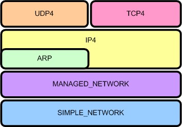 |
|---|
| Figure 1. UEFI Network layering |
This is a sub-project of the EDK project. Beginning with the developer snapshot 20060807, the UEFI network stack support has been added to the EDK. The UEFI network stack drivers bring the support of TCP/IP networking to EDK, with different drivers implementing different TCP/IP protocols. The hierarchal layering of the drivers is shown at right. (For further information about the UEFI network stack, read the chapter 20-24 of The UEFI specification 2.0 from UEFI.org)
To help develop networking applications, this sub-project provides a SNPNT32 driver which implements the EFI_SIMPLE_NETWORK_PROTOCOL for the NT32 platform. This driver in conjunction with the UEFI network stack drivers can be used to develop and test networking applications on Windows® NT operating system through the EDK’s NT32 platform emulation environment.
The SNPNT32 driver depends on the WinPcap® to transmit and receive packets on the Windows® system. To limit the number of symbols imported into the NT32 platform, SnpNt32 call the functions in the SnpNt32Io dynamic library to transmit/receive packets. The SnpNt32Io library in turn consumes the service provided by WinPcap®. This sub-project (Network-IO) produces the SnpNt32Io library.
The Network-IO project was released under the BSD license .
Using the Network-IO
The UEFI network stack getting started guide contains detailed instructions to start to use the UEFI network stack on NT32 emulator. You can find more information there.
Download the UEFI Network Stack Getting Started Guide(pdf) for guidance on building and using the library to enable UEFI network stack under NT32 Platform Emulator
Download the snapshot or official release of the Network-IO project.
Other Common Links and Downloads
- Directory of Network-IO Source Code Snapshots (Development Versions)
- Directory of Network-IO Source Code Snapshots (Official Releases)
- Link to the TianoCore Community Project
- Link to the UEFI2.0 Specification
- Download WinPcap® library
- Archives of the "Dev" Mailing List
Intel Gig Undi Intel® Ethernet Connections Boot Utility, Preboot Images, and UEFI Drivers - Download Latest Versions of the UEFI Gig Undi Bin and Source:
-
Download preboot.exe and expand to disk
-
Goto APPS\EFI\OPENSRC for undi source. Copy paste InteUndiPkg to edk2 source directory and build
Build -p IntelGigUndiPkg.dsc -
Undi binaries are in EFIx64
Project Points of Contact
- Network-IO Project Owner (China): Ruth Li, Intel Corporation, ruth.li@intel.com
Preboot Execution Environment (PXE)
PXE is a standardized client-server solution that boots an agent via network, allowing management tasks in the absence of a running OS. EDK II has PXE Boot specification compliant implementation for UEFI. This feature is commonly referred to as "PXE boot".
This page describes the operation of PXE. There are separate pages describing how to Enable UEFI PXE Boot in EDK II and Configuring PXE Boot Servers for UEFI.
History & Related Specifications
PXE was introduced as part of the Wired for Management Baseline (WfM) Specification by Intel Corporation in 1997. It was described in a separate PXE 1.0 specification since Wired for Management 2.0. Later, the 2.1 update was published in September 1999.
PXE 2.1 describes the IPv4-based network boot process. It does not cover IPv6-based PXE, but this is described in the UEFI 2.2 specification. The UEFI 2.6 specification describes the IPv6-based PXE process in Section 23.3.1. The DHCP6 options used in PXE process are also described in the UEFI specification.
Related Protocols
The UEFI specification introduces the following protocols related to PXE boot:
- PXE Base Code Protocol – provides several features to utilize the PXE-compatible devices, for network access and network booting.
- PXE Base Code Callback Protocol – provides callback function which will be invoked when the PXE Base Code Protocol is about to transmit, has received, or is waiting to receive a packet.
- Load File Protocol – loads the boot file to specified buffer, which allows the boot manger to boot the file later.
Feature Scope
- Support PXE boot over IPv4 stack, IPv6 stack, or both
- Network Boot Options using PXE are automatically created
- Support PXE Redirection servers (Proxy DHCP servers)
- PXE Vendor Options support (option 43):
- PXE Discovery Control (sub-opt 6, 7)
- PXE Boot Servers (sub-opt 8)
- PXE Boot Menu (sub-opt 9, 10)
PXE Offer Types
There are eight offer types defined in PXEBC_OFFER_TYPE. All of them are supported in IPv4-based PXE. The rules for distinguishing these offers include:
- If the offer is a pure DHCP packet, it is PxeOfferTypeDhcpOnly.
- If the offer does not have DHCP4 option 53, and it contains a DHCP option 67 provides boot file name, it is PxeOfferTypeBootp.
- If the offer has a DHCP4 option 60, or DHCP6 option 16, and the value is starting with “PXEClient”, it is a PXE offer.
- If the PXE offer has a zero “yiaddr” in the DHCP header, it is a proxy offer.
- If the offer has a valid discover vendor option, it is a PXE 1.0 offer.
- If the offer has a valid MTFTP vendor option, it is a WfM 1.1 offer.
The six remaining PXE offers are described below:
| discover vendor option | MTFTP vendor option | N/A | |
|---|---|---|---|
| “PXEClient” available | PxeOfferTypeDhcpPxe10 | PxeOfferTypeDhcpWfm11a | PxeOfferTypeDhcpBinl |
| “PXEClient” available && Yiaddr == 0 | PxeOfferTypeProxyPxe10 | PxeOfferTypeProxyWfm11a | PxeOfferTypeProxyBinl |
Note that “Binl” is a term used in WfM specification and short for “Boot Intervention Network Layer; extended DHCP service”. The offers are selected according to a predefined policy. The priority of the offers is defined in that policy as following:
- PxeOfferTypeDhcpPxe10
- PxeOfferTypeDhcpWfm11a
- PxeOfferTypeProxyPxe10 + PxeOfferTypeDhcpOnly
- PxeOfferTypeProxyWfm11a + PxeOfferTypeDhcpOnly
- PxeOfferTypeDhcpBinl
- PxeOfferTypeProxyBinl + PxeOfferTypeDhcpOnly
- PxeOfferTypeDhcpOnly offer which contains DHCP option 67 for boot file name
- PxeOfferTypeBootp + PxeOfferTypeDhcpOnly
In IPv6-based PXE, only 3 are supported (PxeOfferTypeDhcpBinl, PxeOfferTypeProxyBinl, PxeOfferTypeDhcpOnly).
PXE DHCP Timeout
In IPv4-based PXE, DHCP discovery will be retried four times. The four timeouts are 4, 8, 16 and 32 seconds respectively, to compliant with PXE 2.1 specification. UEFI specification does not define the timeouts for IPv6-based PXE. In current EDKII implementation, DHCPv6 solicit will be retried four times also. The initial retransmission timeout is 4 seconds and maximum retransmission timeout for each retry is 32 seconds. PXE client should wait for the timeout then select most preferred offer among all the received offers.
PXE Boot Process
This section will briefly introduce the PXE boot process, please refer the section 2.2 of PXE v2.1 specification for a
detailed step-by-step synopsis of the PXE protocol.
") The picture shows a typical IPv4 PXE boot flow (it's from PXE Spec V2.1 Figure 2-1).
The picture shows a typical IPv4 PXE boot flow (it's from PXE Spec V2.1 Figure 2-1).
Step 1-4 is DHCP protocol with several extended DHCP option tags. The client should broadcast a DHCP Discover message with "PXEClient" extension tags to trigger the DHCP process. Then it should select offers, get the address configuration and boot path information, and complete the standard DHCP protocol by sending a request for the selected address to the server and waiting for the Ack. It might also need to perform DNS resolution to translate the server's host address to IP address.
Step 5-6 takes place between the client and a Boot Server. The client should select and discover a Boot Server from the obtained server list in step 1-4. This phase is not a part of standard DHCP protocol, but uses the DHCP Request and Ack message format as a convenient for communication. The client should send the request message to port 67 (broadcast) or port 4011 (multicast/unicast) of the selected boot server, and wait a DHCP ack for the boot file name and MTFTP configuration parameters.
Step 7-9 is the downloading of the network bootstrap program (NBP). The client will load the NBP into the computer’s local memory using TFTP, verify the image and execute it finally.
- In a Windows Deployment Services (WDS) environment, the NBP is provided as wdsmgfw.efi.
- In a Linux environment, the NBP is provided by UEFI-enabled boot loaders such as GRUB, GRUB2 or ELILO.
Take UEFI PXE with Microsoft WDS as example, the NBP would continue to download several files to client platform. After the downloading finished, the WDS loader calls ExitBootService() and transits to Runtime phase. The OS kernel starts execution and takes over the control to the system. The OS network stack is also started for handling network operations.
Please refer to UEFI PXE Boot Performance Analysis for more details.
PXE Boot Verification
Operating systems used to verify EDK II PXE Boot functionality:
- Microsoft Windows 10/8.1/7
- SUSE Linux Enterprise 11 (SP3)
- Red Hat Enterprise Linux 7.0
PXE Limitations
- PXE uses UDP as transport layer protocol. TCP is not supported.
- PXE is designed to work within a corporate network, not outside of a company firewall.
- PXE uses TFTP and does not support a secure transport method (ex: HTTPS).
References
- PXE 2.1 specification: http://download.intel.com/design/archives/wfm/downloads/pxespec.pdf
- UEFI 2.6 specification: http://www.uefi.org/sites/default/files/resources/UEFI%20Spec%202_6.pdf
- WfM2.0 specification: http://download.intel.com/design/archives/wfm/downloads/base20.pdf
- UEFI PXE Boot Performance Analysis: https://software.intel.com/sites/default/files/managed/2d/04/intel-uefi-pxe-boot-performance-analysis.pdf
- NetworkPkg Getting Started Guide: NetworkPkg Getting Started Guide
Shell Application To Internal Command
Internal commands of the shell application are almost the same as a UEFI Application, but they have to register with the shell binary that they are compiled into. This means that they are made as libraries and use the initialization routine of the library to perform this registration. Internal commands also have a slight increase in the abilities they can have. All of this extra requirements and features are contained within ShellCommandLib and most only function when linked within the shell binary image. Your command must be linked within the shell binary to the ShellCommandLib
Extra capabilities of internal commands
Internal commands have a few extra capabilities. These should be used very judiciously since these are things that cannot always be reversed once done. Registration (see below) is one of these extras. CommandInit is the initialization command that you need to call at least once.
Alias Support
Internal commands can get more direct access to the list of alias’ inside the shell. This includes getting the list of alias’ and checking for a single alias at a time.
Command Support
Internal commands can get a list of all commands and can get access to the help command for a given command.
Echo Support
Internal commands can determine and change the state of the echo feature.
Exit Support
Internal commands can get and set the ‘exit state’ which determine whether the shell will exit upon completion of the current command. This cannot be undone once set.
Script Manipulation Support
Internal commands can parse and manipulate the script file. This means that they can move the ‘execution point’ of the script around within the script file.
Mapping Support
Internal commands can add, remove, and manipulate the map names in the shell environment. There are a lot of commands having to do with map creation and manipulation. Most of these changes are hard to undo, but the ShellCommandCreateInitialMappingsAndPaths function can pretty much reset everything.
Path and File Support
Files and Paths are manipulated vie many functions. These do not overlap with functions in the ShellLib or the Shell protocols, but extend that to be more feature rich. The major feature here is the conversion to EFI_FILE_PROTOCOL from SHELL_FILE_HANDLE and back.
Registration of a command
The registration API is as follows:
RETURN_STATUS
EFIAPI
ShellCommandRegisterCommandName (
IN CONST CHAR16 *CommandString,
IN SHELL_RUN_COMMAND CommandHandler,
IN SHELL_GET_MAN_FILENAME GetManFileName,
IN UINT32 ShellMinSupportLevel,
IN CONST CHAR16 *ProfileName,
IN CONST BOOLEAN CanAffectLE,
IN CONST EFI_HANDLE HiiHandle,
IN CONST EFI_STRING_ID ManFormatHelp
);
You pass into this command:
- the string you respond to (nominally the command itself)
- the function to call when this command in invoked
- the external filename for help text
- the support level your command requires
- the profile name you are part of
- whether this command can affect ‘Lasterror’ environment variable
- the HII handle that your help text is registered with
- The String Id within HII that your text is retrievable with
Example: integrate PerformancePkg/Dp_App into ShellPkg
These steps should handle most of the required changes. Other cleanup can be done, such as replacing PrintToken() with ShellPrintHiiEx().
Use ShellPkg/Library/UefiShellInstall1CommandsLib as your porting basis.
- Make a new directory in ShellPkg/Library called DpInstall1CommandsLib.
- Using Windows cmd.exe, change directory to ShellPkg/Library.
- Run copy UefiShellInstall1CommandsLib\UefiShellInstall1CommandsLib.* DpInstall1CommandsLib\DpInstall1CommandsLib.*
- Edit DpInstall1CommandsLib.inf
-
Change BASE_NAME to DpUefiShellInstall1CommandsLib
-
Generate a new GUID for FILE_GUID using Visual Studio guidgen.exe or GuidGen.
-
Change [Sources] to list the DP source files (DpUefiShellInstall1CommandsLib.c/h/uni, Dp.c, Dp.h, etc)
-
To [Packages] add PerformancePkg/PerformancePkg.dec
-
To [LibraryClasses] add TimerLib, PerformanceLib, and DxeServicesLib
-
Change [Protocols] to use
gEfiLoadedImageProtocolGuid # ALWAYS_CONSUMED
gEfiDriverBindingProtocolGuid # SOMETIMES_CONSUMED
gEfiComponentName2ProtocolGuid # SOMETIMES_CONSUMED
gEfiLoadedImageDevicePathProtocolGuid # SOMETIMES_CONSUMED
gEfiDevicePathToTextProtocolGuid # SOMETIMES_CONSUMED
-
To [Pcds] add gEfiMdePkgTokenSpaceGuid.PcdUefiLibMaxPrintBufferSize
-
Change [Guids] to use gDpShellInstall1HiiGuid
-
- Edit DpInstall1CommandsLib.uni
- Change all instances of BCFG to DP, keeping the case of the
changed item, e.g.
- Change STR_GET_HELP_BCFG to STR_GET_HELP_DP
- Change .TH bcfg to .TH dp
- Change all help text to reflect help text in DpStrings.uni.
- Change all instances of BCFG to DP, keeping the case of the
changed item, e.g.
- Edit DpInstall1CommandsLib.h
- Change all instances of BCFG to DP, keeping the case of the changed item.
- Change gShellInstall1HiiHandle to gDpShellInstall1HiiHandle.
- Edit DpInstall1CommandsLib.c
-
Change all instances of BCFG to DP, keeping the case of the changed item.
-
Change gShellInstall1HiiHandle to gDpShellInstall1HiiHandle.
-
Include DpUefiShellInstall1CommandsLib.h
-
Add Dp to the start of each function name so they start with DpShell.
-
Change all instances of gShellInstall1HiiHandle to gDpShellInstall1HiiHandle.
-
In DpShellInstall1CommandsLibConstructor, this comment should be above HiiAddPackages().
//
// 3rd parameter 'HII strings array' must be name of .uni strings file followed by 'Strings', e.g. mycommands.uni must be
// specified as 'mycommandsStrings' because the build Autogen process defines this as a string array for the strings in your
// .uni file. Examine your Build folder under your package's DEBUG folder and you will find it defined in a xxxStrDefs.h file.
//
-
- In DpUtilities.c, DpTrace.c, DpProfile.c, DpInternal.h change all instances of gHiiHandle to gDpShellInstall1HiiHandle.
- In Dp.c do the following:
-
Change all instances of gHiiHandle to gDpShellInstall1HiiHandle.
-
Add the following:
#include "DpUefiShellInstall1CommandsLib.h"
#include <Guid/GlobalVariable.h>
#include <Library/PrintLib.h>
#include <Library/HandleParsingLib.h>
#include <Library/DevicePathLib.h>
-
Change InitializeDp to ShellCommandRunDpInstall.
-
Replace the code between GetPerformanceCounter() and ShellCommandLineParse() with the following:
//
// initialize the shell lib (we must be in non-auto-init...)
//
Status = ShellInitialize();
ASSERT_EFI_ERROR(Status);
Status = CommandInit();
ASSERT_EFI_ERROR(Status);
-
- Edit ShellPkg/Include/Guid/ShellLibHiiGuid.h and do the following:
- Add the GUID in DpInstall1CommandsLib.inf and call it SHELL_DP_INSTALL1_HII_GUID.
- Add 'extern EFI_GUID gDpShellInstall1HiiGuid'.
- Edit ShellPkg/ShellPkg.dec and add the GUID in DpInstall1CommandsLib.inf and call it gDpShellInstall1HiiGuid.
- Edit ShellPkg/ShellPkg.dsc and do the following:
-
Add ShellPkg/Library/DpInstall1CommandsLib/DpUefiShellInstall1CommandsLib.inf as a NULL library instance to Shell.inf {} section.
-
Add the appropriate TimerLib and PerformanceLib drivers to the [LibraryClasses] section.
-
Add the following library instances to [LibraryClasses.common]
IoLib|MdePkg/Library/BaseIoLibIntrinsic/BaseIoLibIntrinsic.inf
PciLib|MdePkg/Library/BasePciLibCf8/BasePciLibCf8.inf
PciCf8Lib|MdePkg/Library/BasePciCf8Lib/BasePciCf8Lib.inf
DxeServicesLib|MdePkg/Library/DxeServicesLib/DxeServicesLib.inf
-
Shell Requirements
The shell is explicitly defined as a UEFI 2.1+ Application. That means that is has a requirement on a completed system table and many protocols. The shell will use features only found in UEFI 2.3+ (such as SimpleTextInputEx), but will function with a reduced feature set without these features. Note that these reductions in functionality may make the the shell non-spec compliant.
Table Requirements
The shell uses many functions found on the System Table or sub-tables.
System Table
- EFI Table Header
- ConsoleInHandle
- ConIn
- ConsoleOutHandle
- ConOut
- StandardErrorHandle
- StdErr
Boot Services
All major sections of this table are used.
- Event, Timer, and Task Priority Services
- Memory Allocation Services
- Protocol Handler Services
- Image Services
- Miscelaneous Boot Services
Runtime Services
Many sections of this table are used.
- Variable Services
- Time Services
- Miscelaneous Runtime Services
Protocol Dependancy
The shell uses many UEFI standard protocols to perform.
Required
- gEfiSimpleTextInProtocolGuid
- gEfiSimpleTextOutProtocolGuid
- gEfiSimpleFileSystemProtocolGuid
- gEfiLoadedImageProtocolGuid
- gEfiComponentName2ProtocolGuid
- gEfiUnicodeCollation2ProtocolGuid
- gEfiDevicePathProtocolGuid
- gEfiDevicePathToTextProtocolGuid
- gEfiPciRootBridgeIoProtocolGuid
- gEfiBlockIoProtocolGuid
Optional
These are used for shell nesting operations, but are not required by the first shell instance.
- gEfiShellProtocolGuid
- gEfiShellParametersProtocolGuid
Reduced Feature Optional
Lacking these protocols will reduce the feature set.
- gEfiSimpleTextInputExProtocolGuid
Command Dependant
The main shell and some commands will function without these. Some commands may not function.
- gEfiSimplePointerProtocolGuid
- gEfiDriverHealthProtocolGuid
- gEfiDriverFamilyOverrideProtocolGuid
- gEfiHiiConfigAccessProtocolGuid
- gEfiHiiDatabaseProtocolGuid
- gEfiCpuArchProtocolGuid
- gEfiIp6ProtocolGuid
- gEfiIp6ServiceBindingProtocolGuid
- gEfiIp6ConfigProtocolGuid
ShellPkg Main Libraries
There are 3 main libraries used by almost all shell commands and 2 of these are very usable by shell applications in the ShellPkg.
ShellLib
Used by both commands and applications. Provides easy access to Shell Protocols, File I/O, and printing to the user. This library is functional across both EDK Shell and UEFI Shell and is very useful tor creating applications that are needed to function across Shell environments.
HandleParsingLib
Used by both commands and applications. Provides easy access for manipulating handles. This means things like
- conversion the handle to and from the handle index; the index is the 2 digit hex identifier of the handle seen by the user
- sorting of handles to determine parent controllers, child controllers, or which driver controls a given controller
ShellCommandLib
fully usable only when linked within the shell binary and therefore only by internal shell commands. This provides extra features for internal commands. See Shell Application to internal command.
ShellPkg Other Libraries
There are a couple of other libraries that are less commonly used.
ShellCEntryPointLib
provides a C-looking entrypoint for an application. This should not be used for porting full C applications.
SortLib
provides quick sorting and comparison operations.
PathLib
provides quick file path manipulation operations.
- remove ".", "..", and "/" from file paths.
- eliminate the last item in a path.
ShellPkg Command Libraries
These are all libraries of shell commands and are only intended to be linked directly into the shell. They are NULL-named libraries.
- UefiShellLevel1CommandsLib
- UefiShellLevel2CommandsLib
- UefiShellLevel3CommandsLib
- UefiShellDebug1CommandsLib
- UefiShellDriver1CommandsLib
- UefiShellInstall1CommandsLib
- UefiShellNetwork1CommandsLib
Shell
Shell is a command interpreter for UEFI systems.
- See Shell FAQ for questions on the shell
- See ShellPkg for the EDK II UEFI Shell 2.0 product
- See Efi-shell for the EDK product
UEFI Variable Runtime Cache
The UEFI Variable Runtime Cache feature was introduced to reduce the total number of SMIs triggered and therefore total system time in SMM when SMM UEFI variables are enabled.
- Pros:
- Improves system boot time
- Improves system stability
- Reduces SMI impact on the operating system (of particular importance in real-time operating systems)
- Cons:
-
Increases in runtime system memory
Note: The memory increase is relatively minimal where the increase size is equal to the sum of the size of all non-volatile UEFI variable stores on the platform. Typically there is just one non-volatile variable store.
-
The feature is enabled and disabled by the following FeaturePCD in MdeModulePkg:
## Indicates if the UEFI variable runtime cache should be enabled.
# This setting only applies if SMM variables are enabled. When enabled, all variable
# data for Runtime Service GetVariable () and GetNextVariableName () calls is retrieved
# from a runtime data buffer referred to as the "runtime cache". An SMI is not triggered
# at all for these requests. Variables writes still trigger an SMI. This can greatly
# reduce overall system SMM usage as most boots tend to issue far more variable reads
# than writes.
# TRUE - The UEFI variable runtime cache is enabled.
# FALSE - The UEFI variable runtime cache is disabled.
# @Prompt Enable the UEFI variable runtime cache.
gEfiMdeModulePkgTokenSpaceGuid.PcdEnableVariableRuntimeCache|TRUE|BOOLEAN|0x00010039
The default PCD value is TRUE meaning the feature is enabled by default. The feature can be disabled by simply setting the PCD value to "FALSE" in a platform DSC file.
Problem Statement
The UEFI Runtime Service GetVariable () is called very often throughout the boot including OS runtime. Each Runtime Service GetVariable () call triggers an SMI which negatively impacts system performance.
Issues with SMM
SMM is typically undesirable for at least the following reasons:
- Core rendezvous: When the system enters SMM, all CPU activity is blocked at other privilege levels.
- Interrupt latency: Real-Time Operating Systems (RTOS) have stringent requirements to service system interrupts which is severely impacted by frequent SMIs at OS runtime.
Platforms Have Little Choice
Today's computer systems must comply with a myriad of industry specifications that often leverage the UEFI variable mechanism as defined in the UEFI specification as a form of OS independent non-volatile storage. In some cases, system software interacts with UEFI variables outside the control of user software impacted. The following examples are intended to help illustrate this statement.
- Firmware interfaces such as UEFI capsule update requires UEFI variables.
- Industry specifications define variables such as BootOrder, OsIndications, and UEFI Secure Boot related variables such as pk, kek, db, dbx, etc. creating an interface between the platform firmware and operating system.
- Operating systems such as Microsoft Windows 10 sometimes issue periodic UEFI variable reads independent of user software.
- Operating systems such as Microsoft Windows 10 use UEFI variables to manage checkpoints of disk dumps during bug check scenarios.
In any case, reducing the overall system impact due to UEFI variables benefits all software on the system.
Sample GetVariable () Impact
The following data is intended to show why this feature can be useful. Assume an RTOS has a maximum latency allowance of 10us. The following measurements were taken from an Intel® Apollo Lake Reference and Validation Platform and show this threshold is not achievable with any SMM involvement.
| Observation | Duration |
|---|---|
| Pure SMI entry latency (RSM w/ no rendezvous) | 40us |
| Dummy SMI handler (port 0xB2 I/O port w/ 0x88) | 180us |
| RT->GetVariable () (called for an existing UEFI variable) | 220us |
| RT->GetVariable () (called for a non-existing UEFI variable) | 272us |
This data does not reflect the performance of the product in any particular configuration and is only provided for illustrative purposes of the relative duration for the given scenarios.
A Phased Approach
Ideally, SMM could be eliminated entirely. However, SMM continues to serve a useful purposes in that it provides a ubiquitous isolated execution environment to authenticate UEFI variable requests. Further, SMM provides a trusted software environment to manage UEFI variable transactions to non-volatile storage (e.g. SPI flash or eMMC/UFS RPMB) at OS runtime when hardware enforcement of write access is restricted to SMM.
Priority: Reduce SMM Usage for Getting UEFI Variables
The rationale for preserving SMM applies to SetVariable () but not GetVariable () or GetNextVariableName (). This realization led to the UEFI Variable Runtime cache feature. Fortunately, getting variables as opposed to setting variables is much more common.
On an Intel® Atom Reference and Validation Platform (RVP), it was found that after a first boot (also referred to as a "manufacturing boot" in which many UEFI variables are written to initialize the UEFI variable store), the number of GetVariable () calls exceeded 150 while the number of SetVariable () calls was less than 10. GetVariableName () was also invoked multiple times which is often called many times successively to iterate over the current set of variables each time invoking an SMI.
On the same Intel® Apollo Lake system used in the earlier data table, it was found that with the UEFI Variable Runtime Cache feature enabled, the total GetVariable () time for an existing UEFI variable decreased to 5us from 220us.
Therefore, analysis showed that eliminating SMIs on Runtime Service GetVariable () and GetNextVariableName () calls is possible and can lead to the greatest potential improvement in terms of SMM reduction across the UEFI variable services.
Summary of Changes
The UEFI Variable Runtime Cache feature reduces overall system SMM usage when using VariableSmmRuntimeDxe with VariableSmm for SMM UEFI variables. It does so by eliminating SMM usage for the Runtime Service GetVariable () and GetNextVariableName () functions.
Major Changes
- Two UEFI variable caches will be maintained.
-
"Runtime Cache" - Maintained in VariableSmmRuntimeDxe. Used to serve runtime service GetVariable () and GetNextVariableName () callers.
-
"SMM Cache" - Maintained in VariableSmm to service SMM GetVariable () and GetNextVariableName () callers.
Note: A cache in SMRAM is retained so SMM modules do not operate on data outside SMRAM.
-
- A new UEFI variable read and write flow will be used as described below.
At any given time, the two caches should be coherent. On a variable write, the runtime cache is only updated after validation in SMM and, in the case of a non-volatile UEFI variable, the variable must also be successfully written to non-volatile storage.
Design Details
This section covers various design related details to help provide context and background for this feature.
UEFI Variable Cache Background
A UEFI variable host memory cache existed in the EDK II UEFI variable driver prior to this feature. When SMM UEFI variables are enabled, the cache is maintained in SMRAM by VariableSmm. Hence the previous behavior for a runtime UEFI variable call to trigger an SMI, the SMI handler to check for a cache hit, and then consult non-volatile storage on a cache miss.
In general, the UEFI variable cache before and after this feature serves as a write-through cache of all variable data in the form of a host memory variable store. Volatile UEFI variables are entirely maintained in a host memory variable store although in a different buffer than the non-volatile UEFI variable cache.
Previous UEFI Variable Cache

UEFI Variable Cache with Runtime Cache

High-Level GetVariable () Flow with the Runtime Cache

flow with the runtime cache")
High-Level SetVariable () Flow with the Runtime Cache

flow with the runtime cache")
Runtime & SMM Cache Coherency
The non-volatile cache should always accurately reflect non-volatile storage contents (done today) and the "SMM cache" and "Runtime cache" should always be coherent on access. The runtime cache is only updated by VariableSmm.
Updating both caches from within a SMM SetVariable () operation is fairly straightforward but a race condition can occur if an SMI occurs during the execution of runtime code reading from the runtime cache. To handle this case, a runtime cache read lock is introduced that explicitly moves pending updates from SMM to the runtime cache if an SMM update occurs while the runtime cache is locked. Note that it is not expected a Runtime services call will interrupt SMM processing since all CPU cores rendezvous in SMM.
Runtime DXE Read Flow
- Acquire RuntimeCacheReadLock
- If RuntimeCachePendingUpdate flag (rare) is set then:
- Trigger FlushRuntimeCachePendingUpdate SMI
- Verify RuntimeCachePendingUpdate flag is cleared
- Perform read from RuntimeCache
- Release RuntimeCacheReadLock
FlushRuntimeCachePendingUpdate SMI Flow
- If RuntimeCachePendingUpdate flag is not set:
- Return
- Copy the data at RuntimeCachePendingOffset of RuntimeCachePendingLength to RuntimeCache
- Clear the RuntimeCachePendingUpdate flag
SMM Write Flow
-
Perform variable authentication and the non-volatile write. If either fail, return an error to the caller.
-
If RuntimeCacheReadLock is set then:
- Set RuntimeCachePendingUpdate flag
- Update RuntimeCachePendingOffset and RuntimeCachePendingLength to cover the a superset of the pending chunk (for simplicity, the entire variable store is currently synchronized).
-
Else:
- Update RuntimeCache
-
Update SmmCache
Note: RT read cannot occur during SMI processing since all cores are locked in SMM.
Security Concerns
A common concern raised with this feature is the potential security threat presented by serving runtime services callers from a ring 0 memory buffer of EfiRuntimeServicesData type. The conclusion of analyzing this during the proposal phase was that this change does not fundamentally alter the attack surface. The UEFI variable Runtime Services are invoked from ring 0 and the data already travels through ring 0 buffers (such as the SMM communicate buffer) to reach the caller. Even today if ring 0 is assumed to be malicious, the malicious code could keep one AP in a loop to monitor the communication data, when the BSP gets an (authenticated) variable. When the communication buffer is updated and the status is set to EFI_SUCCESS, the AP could modify the communication buffer contents such that tampered data is returned to the BSP caller. Or an interrupt handler on the BSP could alter the communication buffer contents before the data is returned to the caller. In summary, this feature was not found to introduce any attack not possible today.
USB Stack
If I have a USB dongle, what drivers do I need?
Below are specific paths to the drivers from the open source packages. You can also put in both EHCI and UHCI, and they will work together to select the best controller to use based on the capabilities of the attached USB devices. You also need the Disk I/O Driver and Partition Driver. The FAT driver is available in both source and binary form. The path to the pre-built FAT binary is shown in the list below.
MdeModulePkg/Bus/Pci/EhciDxe/EhciDxe.inf
MdeModulePkg/Bus/Pci/UhciDxe/UhciDxe.in
MdeModulePkg/Bus/Usb/UsbBusDxe/UsbBusDxe.inf
MdeModulePkg/Bus/Usb/UsbMassStorageDxe/UsbMassStorageDxe.inf
MdeModulePkg/Universal/Disk/DiskIoDxe/DiskIoDxe.inf
MdeModulePkg/Universal/Disk/PartitionDxe/PartitionDxe.inf
FatBinPkg/EnhancedFatDxe/Fat.inf
USB Dongles can also be used as a recovery device in the PEI Phase. The following PEIMs would also be required if the PEI Phase needs to load a recovery image from a USB Dongle. The CDExpressPei module would only be required for recovery from a USB CD/DVD.
MdeModulePkg/Bus/Pci/UhciPei/UhciPei.inf
MdeModulePkg/Bus/Pci/EhciPei/EhciPei.inf
MdeModulePkg/Bus/Usb/UsbBotPei/UsbBotPei.inf
MdeModulePkg/Bus/Usb/UsbBusPei/UsbBusPei.inf
MdeModulePkg/Universal/Disk/CdExpressPei/CdExpressPei.inf
FatPkg/FatPei/FatPei.inf
VariablePolicy Protocol - Enhanced Method for Managing Variables
VariablePolicy is -- conceptually -- a follow-on and replacement for the EdkIIVariableLockProtocol and
VariableProperties. It expands upon the capabilities while maintaining a similar interface. The full interface is
described in MdeModulePkg/Include/Protocol/VariablePolicy.h, but the interface and policy structure don't necessarily
give a full picture of the uses of policies, especially some of the more complicated policy constructions. This article
aims to describe some possible VariablePolicy-based solutions. It also describes the required changes for a platform
adopting VariablePolicy for the first time.
Policy Layering
Policy Examples
Platform Porting
If you're picking up the commits containing VariablePolicy for the first time, you will need to make a few changes to your platform DSC files. All of the changes are library-based and linked against VariableServices. The aim was that no matter what flavor of VariableServices you're consuming, you should only have to make changes to the DSC (or even a shared DSC include) and not to any platform FDFs.
VariablePolicyLib Instance
VariablePolicyLib contains the business logic for the VariablePolicy engine, and is now expected by VariableServices.
There are two flavors of VariablePolicyLib: VariablePolicyLib and VariablePolicyLibRuntimeDxe. You must add one
of the following LibraryClasses instances to your DSC file, respective of which flavor of VariableServices you use.
## For SMM-, MM-, or Standalone MM-based VariableServices
[LibraryClasses]
VariablePolicyLib|MdeModulePkg/Library/VariablePolicyLib/VariablePolicyLib.inf
## For RuntimeDxe-based VariableServices.
[LibraryClasses.common.DXE_RUNTIME_DRIVER]
VariablePolicyLib|MdeModulePkg/Library/VariablePolicyLib/VariablePolicyLibRuntimeDxe.inf
VariablePolicyHelperLib Instance
VariablePolicyHelperLib contains common helper functions that are a shorthand for common behaviors when creating and registering a new VariablePolicy (ex. packing the policy structure with the variable names). This library is expected by some of the MdeModulePkg changes that were made to replace VariableLockPolicy. It is also just handy to have available for any parts of the platform code that would like to take advantage of VariablePolicy. You must add the following LibraryClasses instance to your DSC file.
## For all instances.
[LibraryClasses]
VariablePolicyHelperLib|MdeModulePkg/Library/VariablePolicyHelperLib/VariablePolicyHelperLib.inf
VarCheckPolicyLib NULL LibraryClass
If a platform is using the SMM-, MM-, or Standalone MM-based VariableServices, there is a VarCheck lib instance that must be linked to enable VariablePolicy engine. This VarCheck instance also handles MM communication/handler registration.
MdeModulePkg/Universal/Variable/RuntimeDxe/VariableSmm.inf {
## Add this instance to enable VariablePolicy.
NULL|MdeModulePkg/Library/VarCheckPolicyLib/VarCheckPolicyLib.inf
}
PcdAllowVariablePolicyEnforcementDisable
This PCD allows a platform to determine whether the VariablePolicy engine can be disabled. An example of why a platform
would want to disable the engine: it would allow a platform-specific debug mode or refurbishement mode to delete even
protected variables while removing user data. In keeping with EDK2's goal of "default to maximum security", the default
for this PCD is FALSE, meaning any calls to VariablePolicy->DisableVariablePolicy() will fail with
EFI_WRITE_PROTECTED.
If a platform wishes to enable the more flexible mode, they should change this PCD to TRUE.
[PcdsFixedAtBuild]
gEfiMdeModulePkgTokenSpaceGuid.PcdAllowVariablePolicyEnforcementDisable|TRUE
Apppkg
EDK II Standard Libraries and Applications
The EADK (uEfi Application Development Kit) provides a set of standards-based libraries, along with utility and demonstration applications, intended to ease development of UEFI applications based upon the EDK II Open-Source distribution.
At this time, applications developed with the EADK are intended to reside on, and be loaded from, storage separate from the core firmware. This is primarily due to size and environmental requirements.
This release of the EADK should only be used to produce UEFI Applications. Due to the execution environment built by the StdLib component, execution as a UEFI driver can cause system stability issues.
After March 2019 Source: https://github.com/tianocore/edk2-libc/tree/master/AppPkg
Before March 2019 Source: https://github.com/tianocore/edk2/tree/master/AppPkg
See also: EDKII-EADK
ArmPkg Binaries
Prerequisite
cd $EDK2_ROOT
. edksetup.sh `pwd`/BaseTools
make -C BaseTools
FatPkg (tested revision 71 - 2012-06-08)
svn co https://svn.code.sf.net/p/edk2-fatdriver2/code FatPkg-svn --username guest
mv FatPkg-svn/trunk/FatPkg .
build -a ARM -p FatPkg/FatPkg.dsc -t RVCTLINUX -b RELEASE -y report.log
build -a AARCH64 -p FatPkg/FatPkg.dsc -t ARMLINUXGCC -b RELEASE -y report.log
ShellPkg (tested revision 13646 - 2012-08-17)
-
Build the Full Shell:
build -a ARM -p ShellPkg/ShellPkg.dsc -t RVCTLINUX -b RELEASE -y report.log build -a AARCH64 -p ShellPkg/ShellPkg.dsc -t ARMLINUXGCC -b RELEASE -y report.log
-
Without Shell Profiles:
build -a ARM -p ShellPkg/ShellPkg.dsc -t RVCTLINUX -b RELEASE -D NO_SHELL_PROFILES -y report.log build -a AARCH64 -p ShellPkg/ShellPkg.dsc -t ARMLINUXGCC -b RELEASE -D NO_SHELL_PROFILES -y report.log
EdkShellPkg (tested revision 64 - 2014-01-14)
cd EdkShellPkg
svn co https://svn.code.sf.net/p/efi-shell/code/trunk/Shell
-
Edit EdkShellPkg.dsc to replace:
DEFINE EDK_SHELL_DIR = Shell
By:
DEFINE EDK_SHELL_DIR = EdkShellPkg/Shell
-
Patch the EdkShell sources:
cd Shell patch -p1 < ../ShellR64.patch
-
Build it:
cd $EDK2_ROOT build -a ARM -p EdkShellPkg/EdkShellPkg.dsc -t RVCTLINUX -b RELEASE -y report.log
EdkShellPkg: Instructions to generate ShellRn.patch
1. Clone the Shell repository using git git svn clone http://svn.code.sf.net/p/efi-shell/code/trunk/Shell
2. Apply current patch cd Shell
Ensure you can apply the current patch before to apply it (the parameter '-p0' might differ): patch -p1 --dry-run < $TIANOCORE_ROOT/EdkShellPkg/ShellR64.patch
Apply the patch: patch -p1 < $TIANOCORE_ROOT/EdkShellPkg/ShellR64.patch
3. Generate the GIT commit - Ensured all the new files have been added: git add Library/Aarch64/ Library/Arm/ git commit -m "EDK Shell patch to support GCC"
4. Generate the new EDK Shell patch git format-patch -1 --stdout > $TIANOCORE_ROOT/EdkShellPkg/ShellR64.patch
ArmPkg Compression
Introduction
To reduce the size of the firmware and also to speed up the boot process (it is sometimes faster to decompress a compressed file than to copy the original file from a block storage), it is often common to compress the DXE & BDS modules.
Disable compression
To speed up the boot process on platform with slow CPU (eg: FPGA platform), it might help to disable the decompression and copy the image directly into DRAM. This section will use ArmPlatformPkg/ArmVExpressPkg/ArmVExpress-RTSM-AEMv8Ax4.fdf as an example.
At the end of the build process you will see these three FVs (Firmware Volume):
FV Space Information
FVMAIN_SEC [14%Full] 524288 total, 77504 used, 446784 free
FVMAIN_COMPACT [45%Full] 2621440 total, 1184312 used, 1437128 free
FVMAIN [99%Full] 4004224 total, 4004168 used, 56 free
FVMAIN_SEC is the secure part of the firmware that should live into Trusted Memory. FVMAIN is the compressed image. This FV image is added in FVMAIN_COMPACT.
The compression is driven by the Guided Section in the FDF file. See the section '[FV.FVMAIN_COMPACT]':
FILE FV_IMAGE = 9E21FD93-9C72-4c15-8C4B-E77F1DB2D792 {
SECTION GUIDED EE4E5898-3914-4259-9D6E-DC7BD79403CF PROCESSING_REQUIRED = TRUE {
SECTION FV_IMAGE = FVMAIN
}
}
The GUID 'EE4E5898-3914-4259-9D6E-DC7BD79403CF' corresponds to the LZMA decompression (defined in IntelFrameworkModulePkg/IntelFrameworkModulePkg.dec). This section says it will compress the FV image named 'FVMAIN' into a file named 'FV_IMAGE'.
The FVMAIN FV image is defined above by the section '[FV.FvMain]'.
To disable the compression
1. Flatten the FDF file: Move the content of FVMAIN into FVMAIN_COMPACT:
- remove FV_IMAGE file from FVMAIN_COMPACT
- move all the files from FVMAIN to FVMAIN_COMPACT
If you build the UEFI firmware after this step, you might see your firmware does not fit anymore in the size defined by the FDF file:
Generating FVMAIN_COMPACT FV
########################################
########################################
########################################
###Return Value = 2
GenFv: ERROR 3000: Invalid
the required fv image size 0x46ede8 exceeds the set fv image size 0x280000
2. Increase the size of the FDF file
From:
[FD.RTSM_VE_AEMv8_EFI]
BaseAddress = 0x00000000|gArmTokenSpaceGuid.PcdFdBaseAddress # The base address of the Firmware in NOR Flash.
Size = 0x00300000|gArmTokenSpaceGuid.PcdFdSize # The size in bytes of the FLASH Device
(...)
BlockSize = 0x00001000
NumBlocks = 0x300
(...)
0x00080000|0x00280000
gArmTokenSpaceGuid.PcdFvBaseAddress|gArmTokenSpaceGuid.PcdFvSize
To:
[FD.RTSM_VE_AEMv8_EFI]
BaseAddress = 0x00000000|gArmTokenSpaceGuid.PcdFdBaseAddress # The base address of the Firmware in NOR Flash.
Size = 0x00580000|gArmTokenSpaceGuid.PcdFdSize # The size in bytes of the FLASH Device
(...)
BlockSize = 0x00001000
NumBlocks = 0x580
(...)
0x00080000|0x00500000
gArmTokenSpaceGuid.PcdFvBaseAddress|gArmTokenSpaceGuid.PcdFvSize
3. Build the new firmware:
FV Space Information
FVMAIN_SEC [14%Full] 524288 total, 77504 used, 446784 free
FVMAIN_COMPACT [88%Full] 5242880 total, 4648424 used, 594456 free
ArmPkg Debugging
Backgound
EFI binary format
EFI binary files are not ELF formated files. It means most ARM debugger tools will not understand this format. But an EFI binary file is generated from an EFL binary by the EDK2 BaseTools. The original EFL file can be found under [EDK2_ROOT]/Build/[YOUR_PROJECT]/DEBUG_[YOUR_TOOLCHAIN]/ARM/.../.../DEBUG/[YOUR_EFI_MODULE].dll Example:
Build/ArmRealViewEb-RTSM-A8/DEBUG_RVCTLINUX/ARM/ArmPlatformPkg/Sec/Sec/DEBUG/ArmPlatformSec.dll
The .dll extension is not relevent. These files are really ELF files. The conversion from ELF to PE/COFF will mainly modify the file header (and its size).
Topology of the UEFI Firmware File
A UEFI Firmware File (actually a UEFI Firmware Device - FD file) is a collection of UEFI binaries encapsulated into a single image. The format of this image is defined by the Platform Initialization Specification Volume 3. A Vector Table is located at the base of this file. A 'BL' branch instruction at the base of the firwmare (location of the Reset Entry into the Vector Table) will jump to the first 'SEC' module of the UEFI Firmware Image.
Hardware Debugger & Printed Debug Command lines
The hardware debugger cannot read the command lines printed into the serial console. These command lines are only there to help the firmware engineer to load the symbols for the corresponding modules into his/her debugger tool.
Debugging code when the 'Debug Command lines' are printed into the serial console
1. Stop your target (eg: with a hardware debugger)
2. Identify the value of the 'PC' (Program Counter Register)
3. Use the printed debug command lines to identify in which module your 'PC' is located. Example:
Boot firmware (version built at 17:48:18 on Aug 21 2012)
add-symbol-file /work/dev/uefi/edk2/Build/ArmVExpress-CTA9x4-Standalone/DEBUG_RVCTLINUX/ARM/ArmPlatformPkg/Sec/Sec/DEBUG/ArmPlatformSec.dll 0x44000180 Trust Zone Configuration is disabled add-symbol-file /work/dev/uefi/edk2/Build/ArmVExpress-CTA9x4-Standalone/DEBUG_RVCTLINUX/ARM/ArmPlatformPkg/PrePeiCore/PrePeiCoreMPCore/DEBUG/ArmPlatformPrePeiCore.dll 0x45000180 add-symbol-file /work/dev/uefi/edk2/Build/ArmVExpress-CTA9x4-Standalone/DEBUG_RVCTLINUX/ARM/MdeModulePkg/Core/Pei/PeiMain/DEBUG/PeiCore.dll 0x450049CC (...)
If your PC register is equal to 0x45000248 then your CPU is running code from the 'PrePeiCore' module.
4. Load the symbols by copying and pasting the command line into your debugger.
add-symbol-file /work/dev/uefi/edk2/Build/ArmVExpress-CTA9x4-Standalone/DEBUG_RVCTLINUX/ARM/ArmPlatformPkg/PrePeiCore/PrePeiCoreMPCore/DEBUG/ArmPlatformPrePeiCore.dll 0x45000180
Debugging initial bring-up code (SEC phase)
Scope: The UEFI Debug Support has not been initialized yet. And the platform crashes before the UART or any output are available to the firmware engineer.
As you do not have UART yet to print out to the location of the initial symbols, you need to calculate manually the corresponding ELF base address that will be used to load the symbols at the correct location. We will use the base address of the first called function as a reference. 1. Identify the first function following your EDK2 boot flow. If your EDK2 firmware crashes in - the Sec module, then the first function is _ModuleEntryPoint of [EDK2_ROOT]/ArmPlatformPkg/Sec/ - the PrePi module, then the first function is _ModuleEntryPoint of [EDK2_ROOT]/ArmPlatformPkg/PrePi/
2. Retrieve the base address of this symbol in the corresponding ELF file. Example:
$ fromelf -s Build/ArmRealViewEb-RTSM-A8/DEBUG_RVCTLINUX/ARM/ArmPlatformPkg/Sec/Sec/DEBUG/ArmPlatformSec.dll | grep _ModuleEntryPoint 1217 _ModuleEntryPoint 0x00000004 Gb 1 Code De Or:
$ arm-linux-gnueabi-objdump -t Build/ArmRealViewEb-RTSM-A8/DEBUG_RVCTLINUX/ARM/ArmPlatformPkg/Sec/Sec/DEBUG/ArmPlatformSec.dll | grep_ModuleEntryPoint 00000004 g F ER_RO 000000c8 .hidden_ModuleEntryPoint
3. Get the address of _ModuleEntryPoint in the UEFI Firmware file. The first 32bit double word of your firmware should be a 'BL' jump to this entry point.
S:0xEB00005F : BL {pc}+0x184 ; 0x184
Note: 'BL' is a branch relative to the Program Counter (PC) register. In the case of the example, the absolute address of _ModuleEntryPoint will be: 0x0 (base address) + 0x184 (offset from the base address) = 0x184
4. Calculate the translated ELF base address for this first module: Absolute Address of _ModuleEntryPoint on the Target - Absolute Address of _ModuleEntryPoint in the ELF file = 0x184 - 0x004 = 0x180
5. Load the symbols for this module:
```text
add-symbol-file
[EDK2_ROOT]/Build/ArmRealViewEb-RTSM-A8/DEBUG_RVCTLINUX/ARM/ArmPlatformPkg/Sec/Sec/DEBUG/ArmPlatformSec.dll 0x180
```
ArmPkg HowToContributeSct
How To contribute to SCT
Pre-requirements:
- Having an account on Github
- Being a member of the UEFI Forum. The membership list is available here: http://uefi.org/members
- Requesting access to UEFI-SCT Github project: https://github.com/UEFI/UEFI-SCT
1.Fork the Github repository

After forking the repository, it should appear under your own Github
account:

2. Clone the repository on your host machine:
git clone https://github.com/oliviermartin/UEFI-SCT.git
3. Create your branch
git checkout -b om/installsct-fix-backup origin/master
After making your first change, you can see the state of your local GIT repository:
$ git status
On branch om/installsct-fix-backup
Your branch is up-to-date with 'github-olivier/master'.
Changes not staged for commit:
(use "git add ..." to update what will be committed)
(use "git checkout -- ..." to discard changes in working directory)
modified: Application/InstallSct/InstallSct.c
no changes added to commit (use "git add" and/or "git commit -a")
$ git diff
diff --git a/Application/InstallSct/InstallSct.c b/Application/InstallSct/InstallSct.c
index cb9f209..d28e720 100644
--- a/Application/InstallSct/InstallSct.c
+++ b/Application/InstallSct/InstallSct.c
@@ -432,35 +432,6 @@ BackupTests (
}
//
- // Exist. Need to remove or backup
- //
- if (StriCmp (InputBuffer, L"a") == 0) {
- //
- // Backup all
- //
- Status = BackupDirFile (TmpName);
- if (EFI_ERROR (Status)) {
- FreePool (TmpName);
- return Status;
- }
-
- FreePool (TmpName);
- continue;
- } else if (StriCmp (InputBuffer, L"l") == 0) {
- //
- // Remove all
- //
- Status = RemoveDirFile (TmpName);
- if (EFI_ERROR (Status)) {
- FreePool (TmpName);
- return Status;
- }
-
- FreePool (TmpName);
- continue;
- }
-
- //
// User must input a selection
//
while (TRUE) {
Once happy by your changes, you can add them to your future GIT commit:
git add Application/InstallSct/InstallSct.c
And commit it!
git commit
After having completed all your changes, you need to push them to the your GIT repository:
$ git push github-olivier om/installsct-fix-backup
Username for 'https://github.com': oliviermartin
Password for 'https://oliviermartin@github.com':
Counting objects: 39, done.
Delta compression using up to 4 threads.
Compressing objects: 100% (19/19), done.
Writing objects: 100% (19/19), 2.92 KiB | 0 bytes/s, done.
Total 19 (delta 13), reused 0 (delta 0)
To https://github.com/oliviermartin/UEFI-SCT.git
* [new branch] om/installsct-fix-backup -> om/installsct-fix-backup
The new branch should now be visible into your fork of UEFI-SCT
project:

To propose your changes to the UEFI-SCT project to be merged, send a
pull-request by clicking on 'Compare & pull request'.

After sending the pull request, the request should appear into the
'UEFI-SCT' project 'pull request' list.

Details of the 'pull-request' can be shown by clicking on the entry:

User can review changes and leave comments:

ArmPkg Profiling
We will take the ARM Versatile Express TC2 (big.LITTLE test chip) as an example in this page.
1. Build UEFI in Release build & Copy the binary to the board. See the instructions in this wiki page
2. Identify the start and end point of your trace. Example on TC2, we want to measure from the start of UEFI at 0xB0000000 - defined into ArmVExpress-CTA15-A7.fdf
[FD.ARM_VEXPRESS_CTA15A7_EFI]
BaseAddress = 0xB0000000|gArmTokenSpaceGuid.PcdFdBaseAddress # The base address of the Firmware in remapped DRAM.
Size = 0x000B0000|gArmTokenSpaceGuid.PcdFdSize # The size in bytes of the FLASH Device
... until the start of Linux. To identfy where we will start Linux we need to load the symbol of the BDS. So start UEFI a first time on the target up to the Boot menu.
Load all the symbols with DS-5 (symbols for Pre-EFI and UEFI phases):
source "/home/olivier/tianocore/ArmPlatformPkg/Scripts/Ds5/cmd_load_symbols.py" -f (0xB0000000,0x000B0000) -m (0x80000000,0x40000000) -v -a
Save the output into a file and replace the entry line to make DS-5 command line. Example:
From:
Add symbols of /home/olivier/tianocore/Build/ArmVExpress-CTA15-A7/RELEASE_GCC48/ARM/ArmPlatformPkg/PrePi/PeiMPCore/DEBUG/ArmPlatformPrePiMPCore.dll at 0xb0000180 Add symbols of /home/olivier/tianocore/Build/ArmVExpress-CTA15-A7/RELEASE_GCC48/ARM/MdeModulePkg/Core/Dxe/DxeMain/DEBUG/DxeCore.dll at 0xbfd62240 Add symbols of /home/olivier/tianocore/Build/ArmVExpress-CTA15-A7/RELEASE_GCC48/ARM/ArmPkg/Drivers/CpuDxe/CpuDxe/DEBUG/ArmCpuDxe.dll at 0xbfd14240 (...)
To:
add-symbol-file /home/olivier/tianocore/Build/ArmVExpress-CTA15-A7/RELEASE_GCC48/ARM/ArmPlatformPkg/PrePi/PeiMPCore/DEBUG/ArmPlatformPrePiMPCore.dll 0xb0000180 add-symbol-file /home/olivier/tianocore/Build/ArmVExpress-CTA15-A7/RELEASE_GCC48/ARM/MdeModulePkg/Core/Dxe/DxeMain/DEBUG/DxeCore.dll 0xbfd62240 add-symbol-file /home/olivier/tianocore/Build/ArmVExpress-CTA15-A7/RELEASE_GCC48/ARM/ArmPkg/Drivers/CpuDxe/CpuDxe/DEBUG/ArmCpuDxe.dll 0xbfd14240 (...)
Save the file into symbols.ds
Go to the assembly view of 'StartLinux'. Find where we start Linux and
set a hardware breakpoint at this location.

Set a hardware breakpoint at the start of UEFI:
hbreak -p *S:0xB0000000
4. After disconnecting the debugger, restart the ARM Versatile Express.
5. Setting up DS-5 for DSTREAM trace with UEFI This tutorial assumes you have already set up DS-5 for hardware debugging UEFI. If you haven't, help can be found here.
Ensure that your DSTREAM's debug probe is connected via a Mictor-38 to the target's trace port. This is in addition to the JTAG connection.
6. Open the Debug Configurations menu and from there open the DTSL
Options window:  In the Trace
Capture tab, select "DSTREAM 4GB Trace Buffer". The other settings are
optional.
In the Trace
Capture tab, select "DSTREAM 4GB Trace Buffer". The other settings are
optional. 
In the Core Trace tab, select "Enable core trace", "Enable core trace",
for each core you want to trace, and optionally "Cycle accurate trace".

On TC2, you should now be in the ARM Boot Monitor Menu.

7. Connect the debugger.
8. Enable your two hardware breakpoints (the start and stop of your trace).
9. Load all the symbols (ie: 'source symbols.ds'). Symbols must be loaded before starting the acquisition.
10. Resume the execution. Start UEFI by typing:
flash run uefi
Program execution should stop at address 0xB0000000.
11. Clear the trace and resume the execution.
UEFI will now boot. As soon as you enter into the Boot Menu press the
boot entry (another alternative would be to automatically start Linux by
setting PcdTimeout... to 0). Program execution should stop again when
reaching the breakpoint you added in stop address.

Results
After some post-processing here are the list of the 20 functions that consume the more cycles on the UEFI Firmware of the ARM Versatile Express TC2.
| Module Name / Function Name | Cycle | Percentage | Count |
|---|---|---|---|
| ArmPlatformPrePiMPCore.dll/LzmaDec_DecodeReal | 1538397019 | 33% | 9 |
| ArmCpuDxe.dll/ArmCleanInvalidateDataCacheEntryBySetWay | 1210112914 | 26% | 18487296 |
| ArmPlatformBds.dll/InternalMemCopyMem | 557552792 | 12% | 99 |
| DxeCore.dll/InternalMemCopyMem | 372182434 | 8% | 26152 |
| ArmPlatformPrePiMPCore.dll/InternalMemCopyMem | 158259634 | 3% | 65 |
| ArmCpuDxe.dll/ArmV7AllDataCachesOperation | 156004379 | 3% | 18489420 |
| VariableRuntimeDxe.dll/__aeabi_uread4 | 67701311 | 1% | 68442 |
| SerialDxe.dll/MmioRead32 | 49657481 | 1% | 167543 |
| DxeCore.dll/InternalMemCompareMem | 48489155 | 1% | 70456 |
| HdLcdGraphicsDxe.dll/MmioRead32 | 28337835 | 0% | 95824 |
| DxeCore.dll/FwVolBlockReadBlock | 27751950 | 0% | 45740 |
| HiiDatabase.dll/InternalMemCopyMem | 21179285 | 0% | 8105 |
| ArmVeNorFlashDxe.dll/InternalMemCopyMem | 14168462 | 0% | 281 |
| DxeCore.dll/FvCheck | 12961574 | 0% | 23193 |
| DxeCore.dll/ReadUnaligned16 | 12397148 | 0% | 27832 |
| ArmCpuDxe.dll/UpdatePageEntries | 11785691 | 0% | 20544 |
| DxeCore.dll/ProduceFVBProtocolOnBuffer | 11522208 | 0% | 14 |
| HiiDatabase.dll/__aeabi_memcpy | 9341275 | 0% | 20710 |
| DxeCore.dll/CoreSetInterruptState | 8332436 | 0% | 32373 |
| ArmPlatformPrePiMPCore.dll/MmioRead32 | 8261530 | 0% | 27246 |
| Function Name | Cycle | Percentage | COunt |
|---|---|---|---|
| LzmaDec_DecodeReal | 1538397019 | 33% | 9 |
| ArmCleanInvalidateDataCacheEntryBySetWay | 1215995571 | 26% | 18504704 |
| InternalMemCopyMem | 1133754058 | 24% | 36242 |
| ArmV7AllDataCachesOperation | 160028408 | 3% | 18515535 |
| MmioRead32 | 86717719 | 1% | 292770 |
| __aeabi_uread4 | 67707303 | 1% | 68453 |
| InternalMemCompareMem | 52567407 | 1% | 76317 |
| FwVolBlockReadBlock | 27751950 | 0% | 45740 |
| ReadUnaligned16 | 13271790 | 0% | 29780 |
| FvCheck | 12961574 | 0% | 23193 |
| UpdatePageEntries | 11785691 | 0% | 20544 |
| ProduceFVBProtocolOnBuffer | 11522208 | 0% | 14 |
| __aeabi_memcpy | 9399629 | 0% | 20814 |
| CoreSetInterruptState | 8332436 | 0% | 32373 |
| VariableWriteServiceInitialize | 7058548 | 0% | 64019 |
| CompareGuid | 6685126 | 0% | 141296 |
| IsErasedFlashBuffer | 6550933 | 0% | 1 |
| InternalMemSetMem32 | 6450910 | 0% | 1800 |
| CoreRestoreTpl | 6072718 | 0% | 15192 |
| NarrowGlyphToBlt | 5892173 | 0% | 20809 |
This is based on SVN rev15539 (2014-05-19).
ArmPkg Runtime
How to write a UEFI Runtime driver
Implementation Rules
- Ensure your driver has been declared with 'MODULE_TYPE = DXE_RUNTIME_DRIVER' in its INF file.
That would load the code and data sections into UEFI memory regions marked as 'Runtime' regions (EfiRuntimeServicesCode and EfiRuntimeServicesData)
-
Allocate all the persistent data into runtime space (ie: use AllocateRuntimePool() instead of AllocatePool())
-
Do not allocate memory in code called after ExitBootServices().
-
Do not access BootServices API during Runtime mode - or protect the code:
if (!EfiAtRuntime ()) { // Raise TPL to TPL_HIGH to stop anyone from interrupting us. OriginalTPL = gBS->RaiseTPL (TPL_HIGH_LEVEL); } -
Declare the controller memory region as Runtime Memory Mapped IO:
// Declare the controller as EFI_MEMORY_RUNTIME Status = gDS->AddMemorySpace ( EfiGcdMemoryTypeMemoryMappedIo, mControllerRegionBase, mControllerRegionSize, EFI_MEMORY_UC | EFI_MEMORY_RUNTIME ); ASSERT_EFI_ERROR (Status);
Status = gDS->SetMemorySpaceAttributes (mControllerRegionBase, mControllerRegionSize, EFI_MEMORY_UC | EFI_MEMORY_RUNTIME); ASSERT_EFI_ERROR (Status);
-
Do not hardcode base addresses in code called after ExitBootServices(). These addresses might need to be fixed up in Operating System Virtual Memory view.
-
Fixup all the controller and dynamic addresses invoked during Runtime mode. Example:
VOID EFIAPI MyDriverVirtualNotifyEvent ( IN EFI_EVENT Event, IN VOID Context ) { EfiConvertPointer (0x0, (VOID*)&mMyControllerBase);
// Convert allocated buffer EfiConvertPointer (0x0, (VOID**)&mMyDriverInstance->Buffer); // Convert BlockIo protocol EfiConvertPointer (0x0, (VOID**)&mMyDriverInstance->BlockIoProtocol.FlushBlocks); EfiConvertPointer (0x0, (VOID**)&mMyDriverInstance->BlockIoProtocol.ReadBlocks); EfiConvertPointer (0x0, (VOID**)&mMyDriverInstance->BlockIoProtocol.Reset); EfiConvertPointer (0x0, (VOID**)&mMyDriverInstance->BlockIoProtocol.WriteBlocks); return;}
DriverEntryPoint () { (...) mMyDriverInstance->Buffer = AllocateRuntimePool (BUFFER_SIZE);
// // Register for the virtual address change event // Status = gBS->CreateEventEx ( EVT_NOTIFY_SIGNAL, TPL_NOTIFY, MyDriverVirtualNotifyEvent, NULL, &gEfiEventVirtualAddressChangeGuid, &mMyDriverVirtualAddrChangeEvent ); ASSERT_EFI_ERROR (Status); (...)}
Validation
UEFI Shell
Confirm the runtime regions are present by using the command 'memmap' in the EFI Shell.
Note: The attribute '8000000000000000' means runtime memory region
UEFI v2.40 (ARM Fixed Virtual Platform EFI Apr 11 2014 11:55:10, 0x00000000)
Shell> memmap
Type Start End #pages Attributes
Available 0000000080000000-0000000087FFFFFF 0000000000008000 000000000000000F
Available 000000008C000000-00000000FFAB0FFF 0000000000073AB1 000000000000000F
BS_Data 00000000FFAB1000-00000000FFFFFFFF 000000000000054F 000000000000000F
Available 0000000880000000-00000008FADC2FFF 000000000007ADC3 000000000000000F
LoaderCode 00000008FADC3000-00000008FAEBAFFF 00000000000000F8 000000000000000F
BS_Code 00000008FAEBB000-00000008FAFB2FFF 00000000000000F8 000000000000000F
RT_Code 00000008FAFB3000-00000008FAFBEFFF 000000000000000C 800000000000000F <-- Runtime
RT_Data 00000008FAFBF000-00000008FAFD7FFF 0000000000000019 800000000000000F <-- Runtime
RT_Code 00000008FAFD8000-00000008FAFF4FFF 000000000000001D 800000000000000F <-- Runtime
Available 00000008FAFF5000-00000008FC6DAFFF 00000000000016E6 000000000000000F
BS_Data 00000008FC6DB000-00000008FC74DFFF 0000000000000073 000000000000000F
Available 00000008FC74E000-00000008FC7C0FFF 0000000000000073 000000000000000F
BS_Data 00000008FC7C1000-00000008FC8B8FFF 00000000000000F8 000000000000000F
Available 00000008FC8B9000-00000008FC8D5FFF 000000000000001D 000000000000000F
BS_Data 00000008FC8D6000-00000008FC906FFF 0000000000000031 000000000000000F
Available 00000008FC907000-00000008FC91EFFF 0000000000000018 000000000000000F
BS_Data 00000008FC91F000-00000008FC95CFFF 000000000000003E 000000000000000F
Available 00000008FC95D000-00000008FC973FFF 0000000000000017 000000000000000F
BS_Data 00000008FC974000-00000008FFE28FFF 00000000000034B5 000000000000000F
Available 00000008FFE29000-00000008FFE91FFF 0000000000000069 000000000000000F
BS_Code 00000008FFE92000-00000008FFFB8FFF 0000000000000127 000000000000000F
RT_Code 00000008FFFB9000-00000008FFFCCFFF 0000000000000014 800000000000000F <-- Runtime
RT_Data 00000008FFFCD000-00000008FFFFEFFF 0000000000000032 800000000000000F <-- Runtime
BS_Data 00000008FFFFF000-00000008FFFFFFFF 0000000000000001 000000000000000F
MMIO 000000000C000000-000000000FFEFFFF 0000000000003FF0 8000000000000001 <-- Runtime (NOR Flash)
MMIO 000000001C170000-000000001C170FFF 0000000000000001 8000000000000001 <-- Runtime (RTC controller)
Reserved : 0 Pages (0)
LoaderCode: 248 Pages (1,015,808)
LoaderData: 0 Pages (0)
BS_Code : 543 Pages (2,224,128)
BS_Data : 15,327 Pages (62,779,392)
RT_Code : 61 Pages (249,856)
RT_Data : 75 Pages (307,200)
ACPI Recl : 0 Pages (0)
ACPI NVS : 0 Pages (0)
MMIO : 16,369 Pages (67,047,424)
Available : 1,015,938 Pages (4,161,282,048)
Total Memory: 4095 MB (4,294,905,856 Bytes)
Shell>
Linux
By passing the argument 'uefi_debug', the Linux kernel dumps the UEFI information. Example:
```text
EFI stub: Booting Linux Kernel...
Initializing cgroup subsys cpu
Linux version 3.14.0-next-20140402+ (gcc version 4.8.3 20131111 (prerelease) (crosstool-NG linaro-1.13.1-4.8-2013.11 -
Linaro GCC 2013.10) ) #1 SMP PREEMPT Fri Apr 11 15:39:25 BST 2014
CPU: AArch64 Processor [410fd0f0] revision 0
bootconsole [earlycon0] enabled
efi: Getting parameters from FDT:
efi: System Table: 0x00000008ffffef18
efi: MemMap Address: 0x00000008fa366018
efi: MemMap Size: 0x00000930
efi: MemMap Desc. Size: 0x00000030
efi: MemMap Desc. Version: 0x00000001
EFI v2.40 by ARM Fixed Virtual Platform EFI Apr 11 2014 11:55:10
efi:
Processing EFI memory map:
0x000080000000-0x000080000fff [Loader Data]
0x000080001000-0x00008007ffff [Conventional Memory]
0x000080080000-0x000080655fff [Loader Data]
0x000080656000-0x000087ffffff [Conventional Memory]
0x00008c000000-0x00009fdfffff [Conventional Memory]
0x00009fe00000-0x00009fe03fff [Loader Data]
0x00009fe04000-0x0000ffab0fff [Conventional Memory]
0x0000ffab1000-0x0000ffffffff [Boot Data]*
0x000880000000-0x0008fa365fff [Conventional Memory]
0x0008fa366000-0x0008fa366fff [Loader Data]
0x0008fa367000-0x0008fa910fff [Loader Code]
0x0008fa911000-0x0008fafb2fff [Boot Code]*
0x0008fafb3000-0x0008fafbefff [Runtime Code]*
0x0008fafbf000-0x0008fafd7fff [Runtime Data]*
0x0008fafd8000-0x0008faff4fff [Runtime Code]*
0x0008faff5000-0x0008fc63cfff [Conventional Memory]
0x0008fc63d000-0x0008fc74dfff [Boot Data]*
0x0008fc74e000-0x0008fc7c0fff [Conventional Memory]
0x0008fc7c1000-0x0008fc8b8fff [Boot Data]*
0x0008fc8b9000-0x0008fc8d5fff [Conventional Memory]
0x0008fc8d6000-0x0008fc906fff [Boot Data]*
0x0008fc907000-0x0008fc91efff [Conventional Memory]
0x0008fc91f000-0x0008fc937fff [Boot Data]*
0x0008fc938000-0x0008fc975fff [Conventional Memory]
0x0008fc976000-0x0008fc981fff [Boot Data]*
0x0008fc982000-0x0008fc98efff [Conventional Memory]
0x0008fc98f000-0x0008fc991fff [Boot Data]*
0x0008fc992000-0x0008fc9b0fff [Conventional Memory]
0x0008fc9b1000-0x0008fce31fff [Boot Data]*
0x0008fce32000-0x0008fce80fff [Conventional Memory]
0x0008fce81000-0x0008ff682fff [Boot Data]*
0x0008ff683000-0x0008ff685fff [Conventional Memory]
0x0008ff686000-0x0008ff686fff [Boot Data]*
0x0008ff687000-0x0008ff698fff [Conventional Memory]
0x0008ff699000-0x0008ff699fff [Boot Data]*
0x0008ff69a000-0x0008ff69dfff [Conventional Memory]
0x0008ff69e000-0x0008ff69efff [Boot Data]*
0x0008ff69f000-0x0008ff69ffff [Conventional Memory]
0x0008ff6a0000-0x0008ff6c4fff [Boot Data]*
0x0008ff6c5000-0x0008ff6cafff [Conventional Memory]
0x0008ff6cb000-0x0008ffe28fff [Boot Data]*
0x0008ffe29000-0x0008ffe8efff [Conventional Memory]
0x0008ffe8f000-0x0008ffe91fff [Loader Data]
0x0008ffe92000-0x0008fffb8fff [Boot Code]*
0x0008fffb9000-0x0008fffccfff [Runtime Code]*
0x0008fffcd000-0x0008ffffefff [Runtime Data]*
0x0008fffff000-0x0008ffffffff [Boot Data]*
0x00000c000000-0x00000ffeffff [Memory Mapped I/O]
0x00001c170000-0x00001c170fff [Memory Mapped I/O]
(...)
Kernel command line: dtb=fvp-base-gicv2-psci.dtb console=ttyAMA0 earlyprintk=pl011,0x1c090000 debug uefi_debug
root=/dev/vda2 rw
(...)
Remapping and enabling EFI services.
EFI remap 0x0008fafb3000 => ffffffc87afb3000
EFI remap 0x0008fafbf000 => ffffffc87afbf000
EFI remap 0x0008fafd8000 => ffffffc87afd8000
EFI remap 0x0008fffb9000 => ffffffc87ffb9000
EFI remap 0x0008fffcd000 => ffffffc87ffcd000
EFI remap 0x00000c000000 => ffffff8000080000
EFI remap 0x00001c170000 => ffffff8000012000
EFI freeing: 0x0000ffab1000-0x0000ffffffff
EFI freeing: 0x0008fa911000-0x0008fafb2fff
EFI freeing: 0x0008fc63d000-0x0008fc74dfff
EFI freeing: 0x0008fc7c1000-0x0008fc8b8fff
EFI freeing: 0x0008fc8d6000-0x0008fc906fff
EFI freeing: 0x0008fc91f000-0x0008fc937fff
EFI freeing: 0x0008fc976000-0x0008fc981fff
EFI freeing: 0x0008fc98f000-0x0008fc991fff
EFI freeing: 0x0008fc9b1000-0x0008fce31fff
EFI freeing: 0x0008fce81000-0x0008ff682fff
EFI freeing: 0x0008ff686000-0x0008ff686fff
EFI freeing: 0x0008ff699000-0x0008ff699fff
EFI freeing: 0x0008ff69e000-0x0008ff69efff
EFI freeing: 0x0008ff6a0000-0x0008ff6c4fff
EFI freeing: 0x0008ff6cb000-0x0008ffe28fff
EFI freeing: 0x0008ffe92000-0x0008fffb8fff
EFI freeing: 0x0008fffff000-0x0008ffffffff
Freed 0x4384000 bytes of EFI boot services memory
(...)
```
Accessing the UEFI variables from the Linux terminal:
```text
root@genericarmv8:~# efibootmgr -d /dev/vda
BootCurrent: 0003
Timeout: 5 seconds
BootOrder: 0003
Boot0000* Linux from SemiHosting
Boot0003 EFI Stub
Boot0005* grub
root@genericarmv8:~#
```
Debugging
To debug UEFI Runtime services, you could have a look at the 'Validation' section to ensure your UEFI Services behave as expected.
If the UEFI Runtime Services are not implemented correctly, your Operating System would crash when accessing them.
Use Case 1: EfiConvertPointer()
1. Trigger the crash in Linux. Keep the failing virtual address and the
values of the PC and LR registers.

- Failing Virtual Adress: 0xffaae850
- PC: 0xffffffc0031c473c
- LR: 0xffffffc0031c4710
2. Get the remapped UEFI Runtime regions of the Linux Virtual Memory
map  ... and find out
which region the failing values are part of:
... and find out
which region the failing values are part of:
- 0x0000831b7000 => 0xffffffc0031b7000
- 0x0000ffa99000 => 0xffffffc07fa99000
And calculate the offset (it is likely the offsets are the same for each mapping). In our case the offste is 0xFFFFFFBF80000000 for both ranges.
From this offset, we can get the corresponding PC value into the UEFI space: 0x831C473C
3. Restart UEFI and load the symbols.
Set a breakpoint (or go to the PC location)
 From this window, we
can see the 'Fvb' variable is at 0xffaae840.
'Fvb->GetPhysicalAddress()' is actually at 0xffaae850.
We can conclude that the Linux kernel was still accessing the address of
Fvb->GetPhysicalAddress in the UEFI memory view.
From this window, we
can see the 'Fvb' variable is at 0xffaae840.
'Fvb->GetPhysicalAddress()' is actually at 0xffaae850.
We can conclude that the Linux kernel was still accessing the address of
Fvb->GetPhysicalAddress in the UEFI memory view.
The fix is to convert this address when the Operating System notifies the change of the Virtual Memory map to the UEFI Runtime Services:
VOID
EFIAPI
NorFlashVirtualNotifyEvent (
IN EFI_EVENT Event,
IN VOID *Context
)
{
(..)
EfiConvertPointer (0x0, (VOID**)&mNorFlashInstance->FvbProtocol.GetPhysicalAddress);
(..)
}
Use Case 2: Boot Service API
1. Get the information from the crash

2. Restart UEFI and load the symbols.
Set a breakpoint (or go to the PC location)

Conclusion: AllocatePool (UEFI Boot Services function) is invoked during the UEFI Runtime phase (after gBS->ExitBootServices() is called). It is illegal!
Use Case 3: Direct access to hardware registers
1. Get the information from the crash

0x0c00_0000 is actually the NOR Flash address (see: http://infocenter.arm.com/help/topic/com.arm.doc.dui0677c/BBACIHDC.html). The UEFI Runtime NOR Flash driver accessed the hardware region without updating the base address into the Linux Virtual Memory Map.
To identify which part of the driver is accessing the hardware register, we load the symbols into the Linux Memory map. In UEFI Memory map:
Add symbols of /home/olimar01/tianocore/Build/ArmVExpress-FVP-AArch64/DEBUG_GCC48/AARCH64/ArmPlatformPkg/Drivers/NorFlashDxe/NorFlashDxe/DEBUG/ArmVeNorFlashDxe.dll at 0x831d4260
After converting the UEFI address into the Linux Memory Map (and force the symbols to be loaded in EL1 Non-Secure world):
add-symbol-file /home/olimar01/tianocore/Build/ArmVExpress-FVP-AArch64/DEBUG_GCC48/AARCH64/ArmPlatformPkg/Drivers/NorFlashDxe/NorFlashDxe/DEBUG/ArmVeNorFlashDxe.dll EL1N:0xFFFFFFC0031D4260
2. Restart the environment. Load the symbols and add the breakpoint:
add-symbol-file /home/olimar01/tianocore/Build/ArmVExpress-FVP-AArch64/DEBUG_GCC48/AARCH64/ArmPlatformPkg/Drivers/NorFlashDxe/NorFlashDxe/DEBUG/ArmVeNorFlashDxe.dll EL1N:0xFFFFFFC0031D4260 hbreak -p EL1N:0xffffffc0031d8e14
 RuntimeUseCase-7.PNG
Conclusion: Fixing up Instance->DeviceAddress (physical address
of the NOR Flash device) when the virtual memory map is changed at
Runtime should fix the issue.
RuntimeUseCase-7.PNG
Conclusion: Fixing up Instance->DeviceAddress (physical address
of the NOR Flash device) when the virtual memory map is changed at
Runtime should fix the issue.
Tuning
We saw earlier there were multiple UEFI Data and Code Runtime regions in the EFI Shell.
UEFI v2.40 (ARM Fixed Virtual Platform EFI Apr 11 2014 11:55:10, 0x00000000)
Shell> memmap
Type Start End #pages Attributes
Available 0000000080000000-0000000087FFFFFF 0000000000008000 000000000000000F
Available 000000008C000000-00000000FFAB0FFF 0000000000073AB1 000000000000000F
BS_Data 00000000FFAB1000-00000000FFFFFFFF 000000000000054F 000000000000000F
Available 0000000880000000-00000008FADC2FFF 000000000007ADC3 000000000000000F
LoaderCode 00000008FADC3000-00000008FAEBAFFF 00000000000000F8 000000000000000F
BS_Code 00000008FAEBB000-00000008FAFB2FFF 00000000000000F8 000000000000000F
RT_Code 00000008FAFB3000-00000008FAFBEFFF 000000000000000C 800000000000000F <-- Runtime
RT_Data 00000008FAFBF000-00000008FAFD7FFF 0000000000000019 800000000000000F <-- Runtime
RT_Code 00000008FAFD8000-00000008FAFF4FFF 000000000000001D 800000000000000F <-- Runtime
Available 00000008FAFF5000-00000008FC6DAFFF 00000000000016E6 000000000000000F
BS_Data 00000008FC6DB000-00000008FC74DFFF 0000000000000073 000000000000000F
Available 00000008FC74E000-00000008FC7C0FFF 0000000000000073 000000000000000F
BS_Data 00000008FC7C1000-00000008FC8B8FFF 00000000000000F8 000000000000000F
Available 00000008FC8B9000-00000008FC8D5FFF 000000000000001D 000000000000000F
BS_Data 00000008FC8D6000-00000008FC906FFF 0000000000000031 000000000000000F
Available 00000008FC907000-00000008FC91EFFF 0000000000000018 000000000000000F
BS_Data 00000008FC91F000-00000008FC95CFFF 000000000000003E 000000000000000F
Available 00000008FC95D000-00000008FC973FFF 0000000000000017 000000000000000F
BS_Data 00000008FC974000-00000008FFE28FFF 00000000000034B5 000000000000000F
Available 00000008FFE29000-00000008FFE91FFF 0000000000000069 000000000000000F
BS_Code 00000008FFE92000-00000008FFFB8FFF 0000000000000127 000000000000000F
RT_Code 00000008FFFB9000-00000008FFFCCFFF 0000000000000014 800000000000000F <-- Runtime
RT_Data 00000008FFFCD000-00000008FFFFEFFF 0000000000000032 800000000000000F <-- Runtime
BS_Data 00000008FFFFF000-00000008FFFFFFFF 0000000000000001 000000000000000F
MMIO 000000000C000000-000000000FFEFFFF 0000000000003FF0 8000000000000001 <-- Runtime (NOR Flash)
MMIO 000000001C170000-000000001C170FFF 0000000000000001 8000000000000001 <-- Runtime (RTC controller)
Reserved : 0 Pages (0)
LoaderCode: 248 Pages (1,015,808)
LoaderData: 0 Pages (0)
BS_Code : 543 Pages (2,224,128)
BS_Data : 15,327 Pages (62,779,392)
RT_Code : 61 Pages (249,856) <-- Runtime Code regions
RT_Data : 75 Pages (307,200) <-- Runtime Data regions
ACPI Recl : 0 Pages (0)
ACPI NVS : 0 Pages (0)
MMIO : 16,369 Pages (67,047,424)
Available : 1,015,938 Pages (4,161,282,048)
Total Memory: 4095 MB (4,294,905,856 Bytes)
Shell>
These fragmented UEFI regions would still appear fragmented when booting Linux:
Remapping and enabling EFI services.
EFI remap 0x0008fafb3000 => ffffffc87afb3000
EFI remap 0x0008fafbf000 => ffffffc87afbf000
EFI remap 0x0008fafd8000 => ffffffc87afd8000
EFI remap 0x0008fffb9000 => ffffffc87ffb9000
EFI remap 0x0008fffcd000 => ffffffc87ffcd000
EFI remap 0x00000c000000 => ffffff8000080000
EFI remap 0x00001c170000 => ffffff8000012000
These regions can get unify by declaring EFI_MEMORY_TYPE_INFORMATION using the gEfiMemoryTypeInformationGuid HOB. Support for this HOB already exists in the ARM Platform framework, you only need to:
-
Set PcdPrePiProduceMemoryTypeInformationHob to TRUE
-
Define the number of pages for the Runtime Data and Code regions:
--- a/ArmPlatformPkg/ArmVExpressPkg/ArmVExpress.dsc.inc +++ b/ArmPlatformPkg/ArmVExpressPkg/ArmVExpress.dsc.inc @@ -318,8 +318,8 @@ gEmbeddedTokenSpaceGuid.PcdMemoryTypeEfiACPIReclaimMemory|0 gEmbeddedTokenSpaceGuid.PcdMemoryTypeEfiACPIMemoryNVS|0 gEmbeddedTokenSpaceGuid.PcdMemoryTypeEfiReservedMemoryType|0
- gEmbeddedTokenSpaceGuid.PcdMemoryTypeEfiRuntimeServicesData|50
- gEmbeddedTokenSpaceGuid.PcdMemoryTypeEfiRuntimeServicesCode|20
- gEmbeddedTokenSpaceGuid.PcdMemoryTypeEfiRuntimeServicesData|80
- gEmbeddedTokenSpaceGuid.PcdMemoryTypeEfiRuntimeServicesCode|65 gEmbeddedTokenSpaceGuid.PcdMemoryTypeEfiBootServicesCode|400 gEmbeddedTokenSpaceGuid.PcdMemoryTypeEfiBootServicesData|20000 gEmbeddedTokenSpaceGuid.PcdMemoryTypeEfiLoaderCode|20
After rebuilding the UEFI firmware, your regions should now be unified:
Shell> memmap
Type Start End #pages Attributes
Available 0000000080000000-0000000087FFFFFF 0000000000008000 000000000000000F
Available 000000008C000000-00000000FFAB2FFF 0000000000073AB3 000000000000000F
BS_Data 00000000FFAB3000-00000000FFFFFFFF 000000000000054D 000000000000000F
Available 0000000880000000-00000008FACC1FFF 000000000007ACC2 000000000000000F
LoaderCode 00000008FACC2000-00000008FADB9FFF 00000000000000F8 000000000000000F
BS_Code 00000008FADBA000-00000008FAFA9FFF 00000000000001F0 000000000000000F
Available 00000008FAFAA000-00000008FC5F6FFF 000000000000164D 000000000000000F
BS_Data 00000008FC5F7000-00000008FC707FFF 0000000000000111 000000000000000F
Available 00000008FC708000-00000008FC755FFF 000000000000004E 000000000000000F
BS_Data 00000008FC756000-00000008FC872FFF 000000000000011D 000000000000000F
Available 00000008FC873000-00000008FC88FFFF 000000000000001D 000000000000000F
BS_Data 00000008FC890000-00000008FC8C0FFF 0000000000000031 000000000000000F
Available 00000008FC8C1000-00000008FC8D8FFF 0000000000000018 000000000000000F
BS_Data 00000008FC8D9000-00000008FC8F1FFF 0000000000000019 000000000000000F
Available 00000008FC8F2000-00000008FC92DFFF 000000000000003C 000000000000000F
BS_Data 00000008FC92E000-00000008FC93BFFF 000000000000000E 000000000000000F
Available 00000008FC93C000-00000008FC948FFF 000000000000000D 000000000000000F
BS_Data 00000008FC949000-00000008FC94BFFF 0000000000000003 000000000000000F
Available 00000008FC94C000-00000008FC96AFFF 000000000000001F 000000000000000F
BS_Data 00000008FC96B000-00000008FCDEBFFF 0000000000000481 000000000000000F
Available 00000008FCDEC000-00000008FCE03FFF 0000000000000018 000000000000000F
BS_Data 00000008FCE04000-00000008FCE25FFF 0000000000000022 000000000000000F
Available 00000008FCE26000-00000008FCE2CFFF 0000000000000007 000000000000000F
BS_Data 00000008FCE2D000-00000008FF643FFF 0000000000002817 000000000000000F
Available 00000008FF644000-00000008FF644FFF 0000000000000001 000000000000000F
BS_Data 00000008FF645000-00000008FF649FFF 0000000000000005 000000000000000F
Available 00000008FF64A000-00000008FF64AFFF 0000000000000001 000000000000000F
BS_Data 00000008FF64B000-00000008FFDDDFFF 0000000000000793 000000000000000F
Available 00000008FFDDE000-00000008FFE47FFF 000000000000006A 000000000000000F
BS_Code 00000008FFE48000-00000008FFF6DFFF 0000000000000126 000000000000000F
RT_Code 00000008FFF6E000-00000008FFFAEFFF 0000000000000041 800000000000000F <-- Runtime
RT_Data 00000008FFFAF000-00000008FFFFEFFF 0000000000000050 800000000000000F <-- Runtime
BS_Data 00000008FFFFF000-00000008FFFFFFFF 0000000000000001 000000000000000F
MMIO 000000000C000000-000000000FFEFFFF 0000000000003FF0 8000000000000001 <-- Runtime
MMIO 000000001C170000-000000001C170FFF 0000000000000001 8000000000000001 <-- Runtime
Reserved : 0 Pages (0)
LoaderCode: 248 Pages (1,015,808)
LoaderData: 0 Pages (0)
BS_Code : 790 Pages (3,235,840)
BS_Data : 15,401 Pages (63,082,496)
RT_Code : 65 Pages (266,240) <-- Runtime Code regions
RT_Data : 80 Pages (327,680) <-- Runtime Data regions
ACPI Recl : 0 Pages (0)
ACPI NVS : 0 Pages (0)
MMIO : 16,369 Pages (67,047,424)
Available : 1,015,608 Pages (4,159,930,368)
Total Memory: 4095 MB (4,294,905,856 Bytes)
Shell>
And when booting Linux:
Remapping and enabling EFI services.
EFI remap 0x0008fff6e000 => ffffffc87ff6e000
EFI remap 0x0008fffaf000 => ffffffc87ffaf000
EFI remap 0x00000c000000 => ffffff8000080000
EFI remap 0x00001c170000 => ffffff8000012000
ArmPkg
ArmPkg provides ARM architectural protocols common to most of ARM platforms. (CU Arch. Protocol, Hardware Interrupt Protocol, MMU & Coprocessor helper API, ect.)
Various ARM architectures (from ARMv4T to ARMv7) are currently supported by this package. MPCore and Trustzone support are present through helper libraries.
Source Repository
ArmPlatformPkg AArch64
Introduction
These instructions are to build and run UEFI on the AArch64 Foundation or Base FVPs (Fixed Virtual Platforms). FVPs are fixed configurations of ARM Fast Models; they are also known as RTSMs (Real Time System Models). The Base FVP is an evolution of the VE (Versatile Express) RTSM. While the AArch64 Foundation FVP is free to download, the Base FVP requires an ARM license. The Base FVP has additional debugging and configuration features.
Requirement:
- A 32-bit or 64-bit Linux host machine. Support for MS Windows-based toolchains has not been added to the EDK2 BaseTools.
Getting the EDK2 Source with AArch64 support (ARM 64-bit architecture)
1) Get the requirements
A Universally Unique Id (UUID) header. Needed to build the EDK2 BaseTools. On Ubuntu: sudo apt-get install uuid-dev
2) Download the sources
git clone git@github.com:tianocore/edk2.git
git clone https://github.com/tianocore/edk2-platforms.git
Build EDK2 Tianocore
1) Install AArch64 GNU toolchain:
sudo apt install gcc-aarch64-linux-gnu
2) Build EDK2:
cd $(WORKROOT)/edk2
The first time you create your environment, you will need to build the EDK2 source tree
. edksetup.sh
make -C BaseTools
Note: You might need to unset some environment variables if you are working in the same shell and a different EDK2 repository than your usual EDK2 development environment. Otherwise some conflicts might exist between both EDK2 development environments.
unset ARCH WORKSPACE
-
Declare the EDK2 package paths:
export PACKAGES_PATH=$PWD:$PWD/edk2-platforms
-
For the Foundation and Base FVPs (defined by the DSC file ArmPlatformPkg?/ArmVExpressPkg/ArmVExpress-RTSM-AEMv8Ax4-foundation.dsc):
GCC5_AARCH64_PREFIX=aarch64-linux-gnu- build -a AARCH64 -p Platform/ARM/VExpressPkg/ArmVExpress-FVP-AArch64.dsc -t GCC5
Once built, the UEFI Firmware is the following file Build/ArmVExpress-FVP-AArch64/DEBUG_GCC5/FV/FVP_AARCH64_EFI.fd
Note 1: To build the release build, add '-b RELEASE'. Here's an example with the Foundation FVP:
GCC5_AARCH64_PREFIX=aarch64-linux-gnu- build -a AARCH64 -p Platform/ARM/VExpressPkg/ArmVExpress-FVP-AArch64.dsc -t GCC5 -b RELEASE
Start Linux from UEFI on the FVPs
Build AArch64 Linux
1) Get the AArch64 Linux sources
git clone git://git.kernel.org/pub/scm/linux/kernel/git/cmarinas/linux-aarch64.git -b soc-armv8-model
cd linux-aarch64
2) Build the AArch64 kernel with Virtio support
make ARCH=arm64 mrproper
make ARCH=arm64 defconfig
Enable Virtio Disk and Ext4 support in the kernel. The Linaro disk file-system uses Ext4.
make ARCH=arm64 menuconfig
Device Drivers ---> Virtio drivers ---> <*> Platform bus driver for memory mapped virtio devices
Device Drivers ---> [*] Block devices ---> <*> Virtio block driver
File systems ---> <*> The Extended 4 (ext4) filesystem
Build the kernel.
make -j4 ARCH=arm64
CROSS_COMPILE=<path-to-aarch64-gcc>/gcc-linaro-aarch64-linux-gnu-4.8-2013.06_linux/bin/aarch64-linux-gnu-
You should get the binaries:
- arch/arm64/boot/Image
- arch/arm64/boot/dts/foundation-v8.dtb
- arch/arm64/boot/dts/rtsm_ve-aemv8a.dtb
Run Linux from UEFI on the Foundation FVP
1) Download the Foundation FVP: http://www.arm.com/fvp
Decompress the AArch64 Foundation FVP
tar xf ~/FM000-KT-00035-r0p8-48rel5.tgz
2) The current version of the Foundation FVP can only start an ELF image. To workaround this limitation, we use the 'uefi-aarch64-bootstrap' to start the UEFI image on this model.
To build the 'uefi-aarch64-bootstrap':
pushd ArmPlatformPkg/ArmVExpressPkg/Scripts/uefi-aarch64-bootstrap/
CROSS_COMPILE=<path-to-aarch64-gcc>/gcc-linaro-aarch64-linux-gnu-4.8-2013.06_linux/bin/aarch64-linux-gnu- make
popd
3) The Foundation FVP takes an option for an ELF file to be loaded as well as an option to load a binary data blob into RAM.
Linux kernel (filename = 'Image') and the Device Tree Binary (filename = 'foundation-v8.dtb') are expected to be found in the directory where the model is started from.
A file system example can be downloaded from Linaro:
wget http://releases.linaro.org/13.06/openembedded/aarch64/vexpress64-openembedded_minimal-armv8_20130623-376.img.gz
gunzip vexpress64-openembedded_minimal-armv8_20130623-376.img.gz
The file-system needs some minimal preparation:
mkdir tmp
fdisk -lu vexpress64-openembedded_minimal-armv8_20130623-376.img
sudo mount -o loop,offset=$((106496 * 512)) vexpress64-openembedded_minimal-armv8_20130623-376.img tmp/
cd tmp
sudo ln -s S35mountall.sh etc/rcS.d/S03mountall.sh
sudo sh -c "echo 'devtmpfs /dev devtmpfs mode=0755,nosuid 0 0' >> etc/fstab"
cd ..
sudo umount tmp/
The following command line can be used to run UEFI in the following manner:
$AARCH64_FOUNDATION_MODEL_ROOT/Foundation_v8 --cores=2 --image=ArmPlatformPkg/ArmVExpressPkg/Scripts/uefi-aarch64-bootstrap/uefi-bootstrap-el3-foundation.axf --nsdata=Build/ArmVExpress-RTSM-AEMv8Ax4-foundation/DEBUG_GCC47/FV/RTSM_VE_FOUNDATIONV8_EFI.fd@0xA0000000 --block-device=<path/to>/vexpress64-openembedded_minimal-armv8_20130623-376.img
Note: Do not use a symbolic link to the file-system image. The model will not be able to read the image file.
Run Linux from UEFI on the Base FVP
The Linux kernel (filename = 'Image') and the Device Tree Binary (filename = 'rtsm_ve-aemv8a.dtb') are expected to be found in the directory where the model is started from.
export PATH=ARM_BASE_AEMV8_ROOT:$PATH
export LD_LIBRARY_PATH=ARM_BASE_AEMV8_ROOT:$LD_LIBRARY_PATH
FVP_VE_AEMv8A -C motherboard.flashloader0.fname=Build/ArmVExpress-RTSM-AEMv8Ax4/DEBUG_GCC47/FV/RTSM_VE_AEMV8_EFI.fd
ArmPlatformPkg ArmVExpressPkg Network
Install a DHCP and TFTP servers on your machine
To ease my development I have installed a second dedicated ethernet card on my host machine (... do not forget the crossover cable if directly connected to your development board).
$ /sbin/ifconfig | grep eth
eth0 Link encap:Ethernet HWaddr 00:24:1d:0c:1b:a8
eth1 Link encap:Ethernet HWaddr 00:00:5a:11:8b:35
The DHCP and TFTP servers will be attached to eth1. The following instructions are based on Ubuntu, this wikipage should not be considered as the reference documentation to install these network services. They are only there for information. Please look at your OS/Linux distribution documentation for a proper settings.
Install the DHCP server
sudo apt-get install dhcp3-server
After installing, the final messages should say that the server failed to start, it is expected as the server needs to be configured.
The files you will need to manually edit are:
- /etc/dhcp3/dhcpd.conf : DHCP properties configuration
- /etc/default/dhcp3-server : DHCP network configuration
You need to create a subnet that the DHCP server will serve addresses on. This is done through /etc/dhcp3/dhcpd.conf. A sample subnet declaration is shown below along with other configuration statements essential for success.
ddns-update-style none;
default-lease-time 600;
max-lease-time 7200;
subnet 192.168.1.0 netmask 255.255.255.0 {
range 192.168.1.10 192.168.1.254;
option broadcast-address 192.168.1.255;
}
Now make sure that the server will listen on the correct device by editing /etc/default/dhcp3-server so that INTERFACES is assigned "eth1":
INTERFACES="eth1"
Install the TFTP server
Get the server package
sudo apt-get install tftpd-hpa
The server should fail to start.
Get the client package for testing
sudo apt-get install tftp-hpa
Configure TFTP through /etc/default/tftpd-hpa as follows:
# /etc/default/tftpd-hpa
RUN_DAEMON="yes"
OPTIONS="-l -s /var/lib/tftpboot"
TFTP_USERNAME="tftp"
TFTP_DIRECTORY="/var/lib/tftpboot"
TFTP_ADDRESS="192.168.1.1:69"
TFTP_OPTIONS="--secure"
If the directory /var/lib/tftpboot doesn't exist then create it. This is where you put the files to serve such as "BOOTARM.EFI". Create a file (for the experimentation I will copy $EDK2_ROOT/ShellBinPkg/UefiShell/Arm/Shell.efi as /var/lib/tftpboot/BOOTARM.EFI) and put it in that directory. Now stop the dhcp server if it's running and add the 'filename' line inside your subnet declaration in /etc/dhcp3/dhcpd.conf:
subnet 192.168.1.0 netmask 255.255.255.0 {
range 192.168.1.10 192.168.1.254;
option broadcast-address 192.168.1.255;
filename "BOOTARM.EFI";
}
Note: A DHCP server will always need to provide a filename if it does not support PXE boot to allow the UEFI client to request an IP address. A UEFI client will refuse an IP address of a DHCP server that does not support neither PXE or BOOTP.
You might need to create a group and user for the TFTP service (check if the command `cat /etc/passwd | grep ftp` returns any entry):
sudo groupadd -r tftp
sudo useradd -r -d /var/lib/tftpboot -g tftp -s /sbin/nologin tftp
Configure the Ethernet card
We also need to configure the eth1 device to have a static ip address. There are a few ways to do this, either via a script or through the command line. The command to use to set a static address is:
sudo ifconfig eth1 192.168.1.1 netmask 255.255.255.0
If you want to write the configuration, edit the file /etc/network/interfaces:
auto lo
iface lo inet loopback
auto eth0
iface eth0 inet dhcp
auto eth1
iface eth1 inet static
address 192.168.1.1
netmask 255.255.255.0
network 192.168.1.0
broadcast 192.168.1.255
And finally, restart the network services by running:
sudo /etc/init.d/networking restart
sudo /etc/init.d/dhcp3-server restart
sudo service tftpd-hpa restart
Let's test of TFTP service. From your terminal:
tftp 192.168.1.1 69
tftp> get BOOTARM.EFI
Now you should see the file you put in /var/lib/tftpboot in the directory you ran tftp from.
Debugging the Ethernet Driver
To debugging the network stack add the bit DEBUG_NET (ie: 0x00004000) to gEfiMdePkgTokenSpaceGuid.PcdDebugPrintErrorLevel to enable the network specific debug information.
ArmPlatformPkg ArmVExpressPkg
Status
Build and Run on EDK2 Subversion revision 14897
-
Requirements
- RVCTv4 or ARM Compiler v5 (supplied in ARM DS-5) or ARMGCC
- Using Ubuntu: gcc, make, uuid-dev
- Using Cygwin: gcc, make, e2fsprogs (needed for uuid.h)
-
Tested with:
- Versatile Express DVD version 5.2 - How to get the latest firmware for ARM Versatile Express?
- Linaro toolchain 2013.08 - Get the latest version
-
Serial Terminal settings
- Baud Rates: 38400
- Data: 8 bit
- Parity: None
- Flow Control: None
Use ICE debugger with Versatile Express
Prior to use ICE debugger with Versatile Express, you will need to update the version of the ICE's firmware. If you have not installed RealView 4.0 SP3, do it. Open "RealView ICE Update" and "Install Firmware Update ...". Install "[ARM_INSTALL_PATH]\RVI\Firmware\3.4\11\ARM-RVI-3.4.0-25-base.rvi" and "[ARM_INSTALL_PATH]\RVI\Firmware\3.4\22\ARM-RVI-3.4.59-59-patch.rvi".
How to build UEFI Versatile Express
For Linux
For the first time
1. Get EDK2 from Tianocore Subversion repository
svn co https://svn.code.sf.net/p/edk2/code/trunk/edk2 edk2 --username guest
2. Set up the environment. And build the EDK2’s tools
. edksetup.sh
make -C BaseTools
3. Ensure the GCC toolchain is in your PATH environment variable or defined by the GCC47_ARM_PREFIX environment variable. Example:
export GCC47_ARM_PREFIX=/opt/gcc-linaro-arm-linux-gnueabihf-4.8-2013.08_linux/bin/arm-linux-gnueabihf-
4. Build the ARM Versatile Express UEFI Firmware
build -a ARM -p ArmPlatformPkg/ArmVExpressPkg/ArmVExpress-CTA9x4.dsc -t GCC47 -D EDK2_ARMVE_STANDALONE=0
5. Edit the ARM Versatile Express configuration file images.txt to declare the location of the UEFI firmware in NOR Flash
TOTALIMAGES: 5 ;Number of Images (Max : 32)
NOR0UPDATE: AUTO ;Image Update:NONE/AUTO/FORCE
NOR0ADDRESS: BOOT ;Image Flash Address
NOR0FILE: \SOFTWARE\bm_v209.axf ;Image File Name
NOR1UPDATE: AUTO ;IMAGE UPDATE:NONE/AUTO/FORCE
NOR1ADDRESS: 44000000 ;Image Flash Address
NOR1FILE: \SOFTWARE\sec_uefi.bin ;Image File Name
NOR1LOAD: 0 ;Image Load Address
NOR1ENTRY: 0 ;Image Entry Point
NOR2UPDATE: AUTO ;IMAGE UPDATE:NONE/AUTO/FORCE
NOR2ADDRESS: 45000000 ;Image Flash Address
NOR2FILE: \SOFTWARE\uefi.bin ;Image File Name
NOR2LOAD: 45000000 ;Image Load Address
NOR2ENTRY: 45000000 ;Image Entry Point
NOR3UPDATE: AUTO ;IMAGE UPDATE:NONE/AUTO/FORCE
NOR3ADDRESS: 46000000 ;Image Flash Address
NOR3FILE: \SOFTWARE\kernel.bin ;Image File Name
NOR3LOAD: 46000000 ;Image Load Address
NOR3ENTRY: 46000000 ;Image Entry Point
NOR4UPDATE: AUTO ;IMAGE UPDATE:NONE/AUTO/FORCE
NOR4ADDRESS: 40000000 ;Image Flash Address
NOR4NAME: BOOTSCRIPT ;Image Name
NOR4FILE: \SOFTWARE\bootscr.txt ;Image File Name
6. To select second NOR Flash as a booting device, replace in the ARM Versatile Express file \SITE1\HBI0191B\board.txt:
SCC: 0x004 0x00001F09
By:
SCC: 0x004 0x10001F09
7. Copy
Build/ArmVExpress-CTA9x4/DEBUG_GCC47/FV/SEC_ARMVEXPRESS_EFI.fd to the
ARM Versatile Express mass storage (available when the board is
connected through USB to your host machine) under the folder SOFTWARE
and name sec_uefi.bin. Example for cygwin:
cp Build/ArmVExpress-CTA9x4/DEBUG_GCC47/FV/SEC_ARMVEXPRESS_EFI.fd /cygdrive/e/SOFTWARE/sec_uefi.bin
8. Start the ARM Versatile Express board. You should read
Waiting for firmware at 0x80000000 ... on the serial port.
9. Copy ARMVEXPRESS_EFI.fd at 0x80000000 with RealView Debugger
readfile,raw,nowarn "[EDK2_PATH]\Build\ArmVExpress-CTA9x4\DEBUG_GCC47\FV\ARMVEXPRESS_EFI.fd"=0x80000000
10. Resume the execution from RealView Debugger
For all subsequent times
1. Build ARM Versatile Express UEFI Firmware
build -a ARM -p ArmPlatformPkg/ArmVExpressPkg/ArmVExpress-CTA9x4.dsc -t GCC47 -D EDK2_ARMVE_STANDALONE=0
2. Start the ARM Versatile Express board. You should read
Waiting for firmware at 0x80000000 ... on the serial port.
3. Copy ARMVEXPRESS_EFI.fd at 0x80000000.
With RealView Debugger
readfile,raw,nowarn "[EDK2_PATH]\Build\ArmVExpress-CTA9x4\DEBUG_GCC47\FV\ARMVEXPRESS_EFI.fd"=0x80000000
With ARM DS-5
restore [EDK2_PATH]/Build/ArmVExpress-CTA9x4/DEBUG_GCC47/FV/ARMVEXPRESS_EFI.fd binary 0x80000000
Note: You can script this copy in DS-5 by adding the following lines in the text box "Execute debugger commands" of the 'Debugger' tab in "Debug Configurations":
interrupt
if $pc==0x80000000
restore ~/tianocore/Build/ArmVExpress-CTA9x4/DEBUG_GCC47/FV/ARMVEXPRESS_EFI.fd binary 0x80000000
end
4. Resume the execution
For RealView Compiler Toolchain on Windows
The command line window needs to be the one from Visual Studio to get the environment variables required to get some development tools (the windows compiler for BaseTools and `nmake`). The EDK2 toolchain name for ARM RealView Compiler Toolchain under a Windows environment is `RVCT`. The EDK2 build system will automatically pick up the RVCT toolchain defined in your PATH. If you want to use a specific version, set the environment variable 'RVCT_TOOLS_PATH':
set RVCT_TOOLS_PATH=[YOUR_TOOLCHAIN_PATH]
For RealView Compiler Toolchain on Linux
The EDK2 toolchain name for ARM RealView under a Linux environment is `RVCTLINUX`. The EDK2 build system will automatically pick up the RVCT toolchain defined in your PATH. If you want to use a specific version, set the environment variable 'RVCT_TOOLS_PATH':
export RVCT_TOOLS_PATH=[YOUR_TOOLCHAIN_PATH]
For RVCT on Cygwin
The EDK2 toolchain name for ARM RealView under a Cygwin environment is `RVCTCYGWIN`. The EDK2 build system will automatically pick up the RVCT toolchain defined in your PATH. If you want to use a specific version, set the environment variable 'RVCT_TOOLS_PATH':
export RVCT_TOOLS_PATH=[YOUR_TOOLCHAIN_PATH]
To support the standalone mode
The full ArmVe UEFI firmware can be written into NOR Flash to allow the entire boot sequence to be done after a cold boot.
build -a ARM -p ArmPlatformPkg/ArmVExpressPkg/ArmVExpress-CTA9x4.dsc -t GCC47 -D EDK2_ARMVE_STANDALONE=1
ARMVEXPRESS_EFI.fd is required to be copied into the ARM Versatile Express board:
cp Build/ArmVExpress-CTA9x4-Standalone/DEBUG_GCC47/FV/SEC_ARMVEXPRESS_EFI.fd /cygdrive/e/SOFTWARE/sec_uefi.bin
cp Build/ArmVExpress-CTA9x4-Standalone/DEBUG_GCC47/FV/ARMVEXPRESS_EFI.fd /cygdrive/e/SOFTWARE/uefi.bin
Trustzone Support
ArmVE's UEFI supports booting Trustzone (two worlds: Secure and Normal
Worlds) and No Trustzone (one world: the CPU remains in Secure World)
supports. Trustzone support is enabled by Enabling SMC TZASC in the Test
Chip SCC Register 1. This register can only be changed by editing the
configuration file of your Versatile Express board:
E:\SITE1\HBI0191B\board.txt Changing: SCC: 0x004 0x10001F09 For:
SCC: 0x004 0x10003F09
Booting Linux
The default entry in the ARM Boot Manager is defined by the PCDs:
- gArmPlatformTokenSpaceGuid.PcdDefaultBootDescription|L"NorFlash"
- gArmPlatformTokenSpaceGuid.PcdDefaultBootDevicePath|L"VenHw(E7223039-5836-41E1-B542-D7EC736C5E59)/MemoryMapped(0,0x46000000,0x462F0000)"
- gArmPlatformTokenSpaceGuid.PcdDefaultBootArgument|"root=/dev/sda2 rootwait debug earlyprintk console=ttyAMA0,38400 mem=1G"
- gArmPlatformTokenSpaceGuid.PcdDefaultBootType|1
The PCD PcdDefaultBootDevicePath expects a Device Path conforms to the UEFI specification. PcdDefaultBootType defines the type of the image pointed by PcdDefaultBootDevicePath.
- PcdDefaultBootDevicePath = 0 for an EFI Application
- PcdDefaultBootDevicePath = 1 for a legacy kernel with ATAG support
- PcdDefaultBootDevicePath = 2 for a kernel with Flat Device Tree (FDT) support
Example of UEFI Device Path:
// Load FDT binary from the Firmware Volume (mapped at 0x80000000)
#define LINUX_KERNEL L"MemoryMapped(11,0x80000000,0x6FEFFFFF)\\zImage.fdt"
// Linux Kernel from a SD Card
#define LINUX_KERNEL L"VenHw(621B6FA5-4DC1-476F-B9D8-52C557D81070)/HD(1,MBR,0x00000000,0xF9,0x3C8907)\\boot\\zImage.fdt"
// Kernel from SATA HD - Partition 2
#define LINUX_KERNEL L"Acpi(PNP0A03,0)/Pci(0|0)/Pci(0|0)/Pci(5|0)/Pci(0|0)/Sata(0,0,0)/HD(2,MBR,0x00076730,0x1F21BF,0x1F21BF)\boot\zImage.fdt"
// Kernel from NOR Flash
#define LINUX_KERNEL L"VenHw(02118005-9DA7-443a-92D5-781F022AEDBB)/MemoryMapped(0,0x46000000,0x462F0000)"
Starting UEFI from ARM Boot Monitor on VExpress Core Tile A15x2-A7x3
1. Build UEFI
export EDK2_DSC=ArmPlatformPkg/ArmVExpressPkg/ArmVExpress-CTA15-A7.dsc
export EDK2_MACROS="-D ARM_BIGLITTLE_TC2=1"
make -f ArmPlatformPkg/Scripts/Makefile
2. Change the Boot core - BootMon use A15-0 as a primary core while UEFI uses A7-0 Change from:
SCC: 0x700 0x00320003 ;CFGRW48 - Boot cluster and CPU (CA15[0])
to:
SCC: 0x700 0x10320003 ;CFGRW48 - Boot cluster and CPU (CA7[0])
3. Configure the VExpress board with UEFI. Change the file SITE1/HBI0249A/images.txt on the VExpress mass-storage such as (note: the Boot Monitor image bm_v513r.axf might have a different name):
TITLE: Versatile Express Images Configuration File
[IMAGES]
TOTALIMAGES: 4 ;Number of Images (Max : 32)
NOR0UPDATE: AUTO ;Image Update:NONE/AUTO/FORCE
NOR0ADDRESS: BOOT ;Image Flash Address
NOR0FILE: \SOFTWARE\bm_v513r.axf ;Image File Name
;NOR0FILE: \SOFTWARE\bm_sram.axf ;Image File Name
NOR1UPDATE: AUTO ;IMAGE UPDATE:NONE/AUTO/FORCE
NOR1ADDRESS: 0x0d000000 ;Image Flash Address
NOR1FILE: \SOFTWARE\uefi.bin ;Image File Name
NOR1LOAD: 0xB0000000
NOR1ENTRY: 0xB0000000
NOR2UPDATE: AUTO ;IMAGE UPDATE:NONE/AUTO/FORCE
NOR2ADDRESS: 0x0e000000 ;Image Flash Address
NOR2FILE: \SOFTWARE\zImage ;Image File Name
NOR2LOAD: 0
NOR2ENTRY: 0
NOR3UPDATE: AUTO ;IMAGE UPDATE:NONE/AUTO/FORCE
NOR3ADDRESS: 0x0e800000 ;Image Flash Address
NOR3FILE: \SOFTWARE\tc2.dtb ;Image File Name
NOR3LOAD: 0
4. Start the board and type:
flash run uefi
Reseting the UEFI Variables stored in the Non Volatile storage on Versatile Express
The UEFI variables are stored in the NOR Flash of the Versatile Express. The UEFI variables are stored on the smaller block size partition of the NOR Flash - NOR Flash access is slow, using smaller block NOR Flash allows to get better performance than using larger block.
To erase the UEFI variables in the Non-Volatile storage, you need to restart the board to use ARM Boot Monitor (the ARM bootloader delivers with the ARM Versatile Express). On some platforms, Boot Monitor is enabled by changing the SCC used to switch NOR Flash mapping to boot either Boot Monitor or UEFI.
At the Bootmon prompt:
> flash
Flash> list areas
Base Area Size Blocks Block Size
---- --------- ------ ----------
0x40000000 65280K 255 256K
0x43FC0000 256K 4 64K
0x44000000 65280K 255 256K
0x47FC0000 256K 4 64K
Flash> erase range 0x43FC0000
Erasing flash
Flash> erase range 0x47FC0000
Erasing flash
Flash>
ARM Fast Model
Launching UEFI on the Model
Different ARM platform models have different parameters. To ensure the parameters you are passing are supported by your model, list the supported parameters by using the argument '-l'. Example:
C:\Program Files\DS-5\bin>RTSM_VE_Cortex-A9_MPx4.exe -l
# Parameters:
# instance.parameter=value #(type, mode) default = 'def value' : description : [min..max]
#----------------------------------------------------------------------------------------------
(...)
motherboard.mmc.p_mmc_file="mmc.dat" # (string, init-time) default = 'mmc.dat' : MMCard filename
motherboard.flashloader1.fname="" # (string, init-time) default = '' : Filename
motherboard.flashloader1.fnameWrite="" # (string, init-time) default = '' : FilenameWrite
motherboard.flashloader0.fname="" # (string, init-time) default = '' : Filename
motherboard.flashloader0.fnameWrite="" # (string, init-time) default = '' : FilenameWrite
(...)
The model supports various devices that UEFI already supports such as the CLCD, the MMC controller, the NOR Flash, the RTC, etc
To start the UEFI in the model, ensure the UEFI firmware is loaded in the NOR Flash mapped at 0x0 (generally NOR Flash 0). Note: At reset, the CPU always starts at 0x0.
Example: UEFI on RTSM Versatile Express Cortex A9x4
1. Build UEFI
. edksetup.sh
build -a ARM -p ArmPlatformPkg/ArmVExpressPkg/ArmVExpress-RTSM-A9x4.dsc -t RVCTLINUX
2. Start the model with UEFI loaded in NOR Flash 0 (using Windows):
RTSM_VE_Cortex-A9_MPx4 -C motherboard.sp810_sysctrl.use_s8=1 -C motherboard.flashloader0.fname=Build\ArmVExpress-RTSM-CTA9x4\DEBUG_RVCT\FV\ARMVEXPRESS_EFI.fd
Or start UEFI from the model Shell (using Linux):
model_shell -m RTSM_VE_Cortex-A9.so -C motherboard.sp810_sysctrl.use_s8=1 -C motherboard.flashloader0.fname=Build/ArmVExpress-RTSM-CTA9x4/DEBUG_RVCTLINUX/FV/ARMVEXPRESS_EFI.fd
Example: Run UEFI SCT on the Model
As said earlier, the model supports MMC, you could even run UEFI Self Certifcation Test (SCT) on the Model: 1. Create a file that will contain the SCT Binaries
mkfs.vfat -C -n MMC_SD_CARD mmc.dat 131072
Note: 131072 is the size is in kilobytes (125M * 1024)
2. Mount the file in the loopback device /dev/loop0:
mkdir fs
sudo mount -o rw,loop=/dev/loop0,uid=`whoami`,gid=`whoami` mmc.dat fs
3. Copy the SCT binaries (ArmPlatformSCT folder) on the mounted filesystem (in the directory 'fs')
Note: If your platform firmware does not have EdkShell binary, you could copy the binary on the filesysem. The EdkShell binary is available in [EDK2_ROOT]/EdkShellBinPkg/FullShell/Arm/Shell_Full.efi
4. Unmount the filesystem
sudo umount fs
5. Start the model with the location of your mmc.dat file with the arguments: -C motherboard.mmc.p_mmc_file="mmc.dat"
6. Start EdkShell and Install SCT (refer to SCT documentation for more details).
Example: Booting Linux on the Model
By default UEFI on RTSM will boot Linux from Semihosting. When using Semihosting support, files are downloaded from the host machine. The file name for the Linux kernel can be found in ArmPlatformPkg/ArmVExpressPkg/ArmVExpress-RTSM-A9x4.dsc:
gArmPlatformTokenSpaceGuid.PcdDefaultBootDevicePath|L"VenHw(C5B9C74A-6D72-4719-99AB-C59F199091EB)/zImage"
A default Device Path may also be specified using the PCD gArmPlatformTokenSpaceGuid.PcdFdtDevicePath. Example for a Device Tree downloaded from Semihosting:
gArmPlatformTokenSpaceGuid.PcdFdtDevicePath|L"VenHw(C5B9C74A-6D72-4719-99AB-C59F199091EB)/vexpress.dtb"
Note: The EFI Device Path Node 'VenHw(C5B9C74A-6D72-4719-99AB-C59F199091EB)' is Semihosting UEFI File System driver (located at ArmPkg/Filesystem/SemihostFs). By default the Semihosting support loads files from the location where the Fast Model has been started. The Semihosting support does not support folder; all files must be in the root of the default location.
Example: Trustzone on the Fast Model
A ARM core with Security Extension (case of most ARMv7 core) always starts in Secure World. But enabling Secure and Non-Secure worlds is not enough to have a Secure Platform, you must have Secure and Non-Secure memory. One way to have Secure and Non-Secure Memory regions is to use Trustzone controllers (see: http://www.arm.com/products/system-ip/controllers/trustzone-controllers.php). The Fast Model VExpress does not have Secure memory (this memory cannot be read from Non-Secure world).
If you want to experiment Secure and Non-Secure worlds on the Fast Model, you can use Non-Secure memory as Secure Memory. To enable both worlds, you must set the PCD gArmTokenSpaceGuid.PcdTrustzoneSupport to TRUE. ArmPlatformPkg/Sec module will be responsible to make the transition from Secure to Non-Secure World.
ArmPlatformPkg Bds
Specify the default Console I/O devices
The UEFI Boot Manager expects all the console peripherals to be defined by the UEFI environment variables ConInDev and ConOutDev. At the time of the first boot of the platform, these variables are not defined yet. To answer this limitation, two PCDs have been introduced for the ARM Boot Manager (ArmPlatformPkg/Bds), the PCDs gArmPlatformTokenSpaceGuid.PcdDefaultConOutPaths and gArmPlatformTokenSpaceGuid.PcdDefaultConInPaths define which devices have to be initialized before the Boot Manager displays its menu.
Example from ARM Versatile Express Cortex A9x4 Core Tile:
# Use the serial console (ConIn & ConOut) and the Graphic driver (ConOut)
gArmPlatformTokenSpaceGuid.PcdDefaultConOutPaths|L"VenHw(D3987D4B-971A-435F-8CAF-4967EB627241)/Uart(38400,8,N,1)/VenPcAnsi();VenHw(407B4008-BF5B-11DF-9547-CF16E0D72085)"
gArmPlatformTokenSpaceGuid.PcdDefaultConInPaths|L"VenHw(D3987D4B-971A-435F-8CAF-4967EB627241)/Uart(38400,8,N,1)/VenPcAnsi()"
- VenHw(D3987D4B-971A-435F-8CAF-4967EB627241)/Uart(38400,8,N,1)/VenPcAnsi(): Device Path of the UART I/O
- VenHw(407B4008-BF5B-11DF-9547-CF16E0D72085): Device Path of the CLCD on the VExpress motherboard
Add an EFI Application to the ArmPlatformPkg BDS
If your EFI Application is in your EFI Firmware, you can follow the same mechanism as EBL. Add your EFI Application to the the list defined by the BootMainEntries variable in [EDK2_ROOT]/ArmPlatformPkg/Bds/BootMenu.c. Example:
EFI_STATUS
BootEFIShell (
IN LIST_ENTRY *BootOptionsList
)
{
EFI_STATUS Status;
// Need to connect every drivers to ensure no dependencies are missing for the application
BdsConnectAllDrivers();
// Start EFI Shell
Status = BdsLoadApplication (mImageHandle, L"ShellFull", 0, NULL);
if (Status == EFI_NOT_FOUND) {
Print (L"Error: EFI Application not found.\n");
} else if (EFI_ERROR(Status)) {
Print (L"Error: Status Code: 0x%X\n",(UINT32)Status);
}
return Status;
}
struct BOOT_MAIN_ENTRY {
CONST CHAR16* Description;
EFI_STATUS (*Callback) (IN LIST_ENTRY *BootOptionsList);
} BootMainEntries[] = {
{ L"EBL", BootEBL },
{ L"EFI Shell", BootEFIShell },
};
Or if your EFI application is located on a storage accessible by UEFI (eg: FileSystem) use the Boot Menu to create a new boot entry:
[1] Linux from SemiHosting
[2] EBL
[3] Boot Manager
Start: 3
Boot Manager options:
[1] Add Boot Device Entry
[2] Update Boot Device Entry
[3] Remove Boot Device Entry
[4] Update FDT path
[5] Return to main menu
Choose option 1-5:
Boot Manager options:
[1] Add Boot Device Entry
[2] Update Boot Device Entry
[3] Remove Boot Device Entry
[4] Update FDT path
[5] Return to main menu
Choose option 1-5: 1
[1] SemihostFs (512 MB)
[2] MMC_SD_CARD (127 MB)
[3] NOR Flash Driver [0x08000000;0x0BFC0000]
[4] Return to previous menu
Select the Boot Device: 2
File path of the EFI Application or the kernel: ShellFull.efi
ArmPlatformPkg SparseMemory
UEFI (and Tianocore) supports non-contiguous system memory regions.
Adding support
One way to add non-contiguous memory is to declare an additional 'Resource Descriptor' HOB during the PEI phase. Example:
EFI_RESOURCE_ATTRIBUTE_TYPE ResourceAttributes;
ResourceAttributes =
EFI_RESOURCE_ATTRIBUTE_PRESENT |
EFI_RESOURCE_ATTRIBUTE_INITIALIZED |
EFI_RESOURCE_ATTRIBUTE_UNCACHEABLE |
EFI_RESOURCE_ATTRIBUTE_WRITE_COMBINEABLE |
EFI_RESOURCE_ATTRIBUTE_WRITE_THROUGH_CACHEABLE |
EFI_RESOURCE_ATTRIBUTE_WRITE_BACK_CACHEABLE |
EFI_RESOURCE_ATTRIBUTE_TESTED;
// Declared the additional DRAM from 2GB to 4GB
SparseMemoryBase = 0x0880000000;
SparseMemorySize = SIZE_2GB;
BuildResourceDescriptorHob (
EFI_RESOURCE_SYSTEM_MEMORY,
ResourceAttributes,
SparseMemoryBase,
SparseMemorySize);
Do not forget to map this region in the MMU Page Table. Otherwise, when the DXE phase would try to load the UEFI modules at the top of the system memory it would crash.
The UEFI code for the Base and Foundation FVP models support the non-contiguous memory. See the code in ArmPlatformPkg/ArmVExpressPkg/Library/ArmVExpressLibRTSM/RTSMMem.c.
Debugging
If the additional memory region has been correctly declared, you should see the EFI modules loaded in this region:
(...)
add-symbol-file /tianocore/Build/ArmVExpress-FVP-AArch64/DEBUG_GCC48/AARCH64/ArmPkg/Drivers/CpuDxe/CpuDxe/DEBUG/ArmCpuDxe.dll 0x8FFFAC800 Loading driver at 0x008FFFAC000 EntryPoint=0x008FFFAC850 ArmCpuDxe.efi add-symbol-file /tianocore/Build/ArmVExpress-FVP-AArch64/DEBUG_GCC48/AARCH64/MdeModulePkg/Core/RuntimeDxe/RuntimeDxe/DEBUG/RuntimeDxe.dll 0x8FFFC6260 Loading driver at 0x008FFFC6000 EntryPoint=0x008FFFC62B0 RuntimeDxe.efi add-symbol-file /tianocore/Build/ArmVExpress-FVP-AArch64/DEBUG_GCC48/AARCH64/MdeModulePkg/Universal/SecurityStubDxe/SecurityStubDxe/DEBUG/SecurityStubDxe.dll 0x8FFFA5260 Loading driver at 0x008FFFA5000 EntryPoint=0x008FFFA52B0 SecurityStubDxe.efi (...)
The system memory is also viewable from the EFI Shell:
UEFI v2.40 (ARM Fixed Virtual Platform EFI Apr 11 2014 11:55:10, 0x00000000)
Shell> memmap
Type Start End #pages Attributes
Available 0000000080000000-0000000087FFFFFF 0000000000008000 000000000000000F
Available 000000008C000000-00000000FFAB0FFF 0000000000073AB1 000000000000000F
BS_Data 00000000FFAB1000-00000000FFFFFFFF 000000000000054F 000000000000000F
Available 0000000880000000-00000008FADC2FFF 000000000007ADC3 000000000000000F
LoaderCode 00000008FADC3000-00000008FAEBAFFF 00000000000000F8 000000000000000F
BS_Code 00000008FAEBB000-00000008FAFB2FFF 00000000000000F8 000000000000000F
RT_Code 00000008FAFB3000-00000008FAFBEFFF 000000000000000C 800000000000000F
RT_Data 00000008FAFBF000-00000008FAFD7FFF 0000000000000019 800000000000000F
RT_Code 00000008FAFD8000-00000008FAFF4FFF 000000000000001D 800000000000000F
Available 00000008FAFF5000-00000008FC6DAFFF 00000000000016E6 000000000000000F
BS_Data 00000008FC6DB000-00000008FC74DFFF 0000000000000073 000000000000000F
Available 00000008FC74E000-00000008FC7C0FFF 0000000000000073 000000000000000F
BS_Data 00000008FC7C1000-00000008FC8B8FFF 00000000000000F8 000000000000000F
Available 00000008FC8B9000-00000008FC8D5FFF 000000000000001D 000000000000000F
BS_Data 00000008FC8D6000-00000008FC906FFF 0000000000000031 000000000000000F
Available 00000008FC907000-00000008FC91EFFF 0000000000000018 000000000000000F
BS_Data 00000008FC91F000-00000008FC95CFFF 000000000000003E 000000000000000F
Available 00000008FC95D000-00000008FC973FFF 0000000000000017 000000000000000F
BS_Data 00000008FC974000-00000008FFE28FFF 00000000000034B5 000000000000000F
Available 00000008FFE29000-00000008FFE91FFF 0000000000000069 000000000000000F
BS_Code 00000008FFE92000-00000008FFFB8FFF 0000000000000127 000000000000000F
RT_Code 00000008FFFB9000-00000008FFFCCFFF 0000000000000014 800000000000000F
RT_Data 00000008FFFCD000-00000008FFFFEFFF 0000000000000032 800000000000000F
BS_Data 00000008FFFFF000-00000008FFFFFFFF 0000000000000001 000000000000000F
MMIO 000000000C000000-000000000FFEFFFF 0000000000003FF0 8000000000000001
MMIO 000000001C170000-000000001C170FFF 0000000000000001 8000000000000001
Reserved : 0 Pages (0)
LoaderCode: 248 Pages (1,015,808)
LoaderData: 0 Pages (0)
BS_Code : 543 Pages (2,224,128)
BS_Data : 15,327 Pages (62,779,392)
RT_Code : 61 Pages (249,856)
RT_Data : 75 Pages (307,200)
ACPI Recl : 0 Pages (0)
ACPI NVS : 0 Pages (0)
MMIO : 16,369 Pages (67,047,424)
Available : 1,015,938 Pages (4,161,282,048)
Total Memory: 4095 MB (4,294,905,856 Bytes)
Shell>
To debug these non-contiguous memory regions with ARM DS-5, you would need to add the new system memory region. Example for the ARM FVP Base model:
source "ArmPlatformPkg/Scripts/Ds5/cmd_load_symbols.py" -f (0x88000000,0x04000000) -m (0x80000000,0x80000000) -m (0x880000000,0x80000000) -a -v
Passing this non-contiguous memory region to Linux
If the Linux image does not contain a EFI Stub then you would need to declare this region in the Device Tree. Example:
```text
memory@80000000 {
device_type = "memory";
reg = <0x00000000 0x80000000 0x0 0x80000000>,
<0x00000008 0x80000000 0x1 0x80000000>;
};
If the Linux image contains the EFI Stub then Linux figures out by
itself the amount of memory exposed by UEFI. Example:
EFI stub: Booting Linux Kernel...
Initializing cgroup subsys cpu
Linux version 3.14.0-next-20140402+ (gcc version 4.8.3 20131111 (prerelease) (crosstool-NG linaro-1.13.1-4.8-2013.11 -
Linaro GCC 2013.10) ) #1 SMP PREEMPT Fri Apr 11 15:39:25 BST 2014
CPU: AArch64 Processor [410fd0f0] revision 0
bootconsole [earlycon0] enabled
efi: Getting parameters from FDT:
efi: System Table: 0x00000008ffffef18
efi: MemMap Address: 0x00000008fa366018
efi: MemMap Size: 0x00000930
efi: MemMap Desc. Size: 0x00000030
efi: MemMap Desc. Version: 0x00000001
EFI v2.40 by ARM Fixed Virtual Platform EFI Apr 11 2014 11:55:10
efi:
Processing EFI memory map:
0x000080000000-0x000080000fff [Loader Data]
0x000080001000-0x00008007ffff [Conventional Memory]
0x000080080000-0x000080655fff [Loader Data]
0x000080656000-0x000087ffffff [Conventional Memory]
0x00008c000000-0x00009fdfffff [Conventional Memory]
0x00009fe00000-0x00009fe03fff [Loader Data]
0x00009fe04000-0x0000ffab0fff [Conventional Memory]
0x0000ffab1000-0x0000ffffffff [Boot Data]*
0x000880000000-0x0008fa365fff [Conventional Memory]
0x0008fa366000-0x0008fa366fff [Loader Data]
0x0008fa367000-0x0008fa910fff [Loader Code]
0x0008fa911000-0x0008fafb2fff [Boot Code]*
0x0008fafb3000-0x0008fafbefff [Runtime Code]*
0x0008fafbf000-0x0008fafd7fff [Runtime Data]*
0x0008fafd8000-0x0008faff4fff [Runtime Code]*
0x0008faff5000-0x0008fc63cfff [Conventional Memory]
0x0008fc63d000-0x0008fc74dfff [Boot Data]*
0x0008fc74e000-0x0008fc7c0fff [Conventional Memory]
0x0008fc7c1000-0x0008fc8b8fff [Boot Data]*
0x0008fc8b9000-0x0008fc8d5fff [Conventional Memory]
0x0008fc8d6000-0x0008fc906fff [Boot Data]*
0x0008fc907000-0x0008fc91efff [Conventional Memory]
0x0008fc91f000-0x0008fc937fff [Boot Data]*
0x0008fc938000-0x0008fc975fff [Conventional Memory]
0x0008fc976000-0x0008fc981fff [Boot Data]*
0x0008fc982000-0x0008fc98efff [Conventional Memory]
0x0008fc98f000-0x0008fc991fff [Boot Data]*
0x0008fc992000-0x0008fc9b0fff [Conventional Memory]
0x0008fc9b1000-0x0008fce31fff [Boot Data]*
0x0008fce32000-0x0008fce80fff [Conventional Memory]
0x0008fce81000-0x0008ff682fff [Boot Data]*
0x0008ff683000-0x0008ff685fff [Conventional Memory]
0x0008ff686000-0x0008ff686fff [Boot Data]*
0x0008ff687000-0x0008ff698fff [Conventional Memory]
0x0008ff699000-0x0008ff699fff [Boot Data]*
0x0008ff69a000-0x0008ff69dfff [Conventional Memory]
0x0008ff69e000-0x0008ff69efff [Boot Data]*
0x0008ff69f000-0x0008ff69ffff [Conventional Memory]
0x0008ff6a0000-0x0008ff6c4fff [Boot Data]*
0x0008ff6c5000-0x0008ff6cafff [Conventional Memory]
0x0008ff6cb000-0x0008ffe28fff [Boot Data]*
0x0008ffe29000-0x0008ffe8efff [Conventional Memory]
0x0008ffe8f000-0x0008ffe91fff [Loader Data]
0x0008ffe92000-0x0008fffb8fff [Boot Code]*
0x0008fffb9000-0x0008fffccfff [Runtime Code]*
0x0008fffcd000-0x0008ffffefff [Runtime Data]*
0x0008fffff000-0x0008ffffffff [Boot Data]*
0x00000c000000-0x00000ffeffff [Memory Mapped I/O]
0x00001c170000-0x00001c170fff [Memory Mapped I/O]
(...)
Kernel command line: dtb=fvp-base-gicv2-psci.dtb console=ttyAMA0 earlyprintk=pl011,0x1c090000 debug uefi_debug
root=/dev/vda2 rw
(...)
Memory: 3972540K/4128768K available (3912K kernel code, 269K rwdata, 1408K rodata, 199K init, 175K bss, 156228K
reserved)
(...)
Remapping and enabling EFI services.
EFI remap 0x0008fafb3000 => ffffffc87afb3000
EFI remap 0x0008fafbf000 => ffffffc87afbf000
EFI remap 0x0008fafd8000 => ffffffc87afd8000
EFI remap 0x0008fffb9000 => ffffffc87ffb9000
EFI remap 0x0008fffcd000 => ffffffc87ffcd000
EFI remap 0x00000c000000 => ffffff8000080000
EFI remap 0x00001c170000 => ffffff8000012000
EFI freeing: 0x0000ffab1000-0x0000ffffffff
EFI freeing: 0x0008fa911000-0x0008fafb2fff
EFI freeing: 0x0008fc63d000-0x0008fc74dfff
EFI freeing: 0x0008fc7c1000-0x0008fc8b8fff
EFI freeing: 0x0008fc8d6000-0x0008fc906fff
EFI freeing: 0x0008fc91f000-0x0008fc937fff
EFI freeing: 0x0008fc976000-0x0008fc981fff
EFI freeing: 0x0008fc98f000-0x0008fc991fff
EFI freeing: 0x0008fc9b1000-0x0008fce31fff
EFI freeing: 0x0008fce81000-0x0008ff682fff
EFI freeing: 0x0008ff686000-0x0008ff686fff
EFI freeing: 0x0008ff699000-0x0008ff699fff
EFI freeing: 0x0008ff69e000-0x0008ff69efff
EFI freeing: 0x0008ff6a0000-0x0008ff6c4fff
EFI freeing: 0x0008ff6cb000-0x0008ffe28fff
EFI freeing: 0x0008ffe92000-0x0008fffb8fff
EFI freeing: 0x0008fffff000-0x0008ffffffff
Freed 0x4384000 bytes of EFI boot services memory
(...)
Last login: Thu Feb 13 16:58:03 UTC 2014 on tty1
root@genericarmv8:~# free -m
total used free shared buffers cached
Mem: 3963 80 3882 0 3 25
-/+ buffers/cache: 52 3910
Swap: 0 0 0
root@genericarmv8:~#
```
ArmPlatformPkg Stack
Stack Topology in ArmPlatformPkg
On MP Core system, the primary core is the core which is responsible for leading the execution in a software stack. In most cases, the primary core is the core 0. But because this is a software specific choice, it can be any core of the CPU. To save memory space in temporary memory, the primary core size has been made distinct from the secondary core stack size. And to make the algorithm simpler, all the cores have been assigned a secondary stack. It means the primary core has been reserved two stack regions, but only uses the primary one.
 ArmPlatformPkgStackTopology.png
If the ARM Secure extension (ie: Trustzone) is supported in software, at
least two set of stacks must be allocated on the platform. The stacks
for the Secure World and the one for the Non Secure/Normal world.
ArmPlatformPkgStackTopology.png
If the ARM Secure extension (ie: Trustzone) is supported in software, at
least two set of stacks must be allocated on the platform. The stacks
for the Secure World and the one for the Non Secure/Normal world.
- PCDs to define stacks in PI/UEFI:
- Stack Base: gArmPlatformTokenSpaceGuid.PcdCPUCoresStackBase - Primary Core Size: gArmPlatformTokenSpaceGuid.PcdCPUCorePrimaryStackSize - Secondary Core Size: gArmPlatformTokenSpaceGuid.PcdCPUCoreSecondaryStackSize
- If Secure World implemented by EDK2, PCDs to define the stacks:
- Stack Base: gArmPlatformTokenSpaceGuid.PcdCPUCoresSecStackBase - Primary Core Size: gArmPlatformTokenSpaceGuid.PcdCPUCoreSecPrimaryStackSize - Secondary Core Size: gArmPlatformTokenSpaceGuid.PcdCPUCoreSecSecondaryStackSize
Note: a separate region for Secure Monitor World stacks can also be defined with PCDs. In case of Secure Monitor stacks, no difference is made between primary and secondary stacks. All cores have the same size. - Secure Monitor Stack Base: gArmPlatformTokenSpaceGuid.PcdCPUCoresSecMonStackBase - Secure Monitor Stack Size: gArmPlatformTokenSpaceGuid.PcdCPUCoreSecMonStackSize
In case of UniCore system, only the primary stack size and stack base need to be defined.
Global Variable region
To make easier to port EDK2 to a new ARM platform, global variables needed during the XIP phase have been defined into common region of the temporary memory to avoid to have to set the base address of each of these global variables everytime we port EDK2 to a new platform. Global variables are defined by an offset in this region. The Global Variable region is automatically set at the top of the primary core stack.
 ArmPlatformPkgGlobalVariableRegion.png
Example to access the global variable B in Normal World, the calculation
should be: PcdCPUCoresStackBase + PcdCPUCorePrimaryStackSize -
PcdPeiGlobalVariableSize + PcdXipVariableBGlobalOffset
ArmPlatformPkgGlobalVariableRegion.png
Example to access the global variable B in Normal World, the calculation
should be: PcdCPUCoresStackBase + PcdCPUCorePrimaryStackSize -
PcdPeiGlobalVariableSize + PcdXipVariableBGlobalOffset
ArmPlatformPkg
ArmPlatformPkg supports UEFI for ARM delveopment boards and their drivers (ARM RealView EB/RTSM, ARM Versatile Express. This package also exposes some common components (such as SEC, PEIMs, BDS) which can be reused by ARM platforms to make the port easier. These components support UniCore and MPCore and are tested on real hardware.
How to port Tianocore/UEFI to a new ARM Platform
There are actually two cases:
- Case 1 - EDK2 from cold boot: the Tianocore project is used to produce the boot firmware that will control the boot process from the first instruction executed after cold boot to the start of the operating system on your platform
- Case 2 - EDK2 as a 2nd stage Boot Loader: the Tianocore project is only used to generate a 2nd (or 3rd) stage boot loader (such as the BeagleBoard)
 ARM-EDK2-Overview.png
Case 1: EDK2 from cold boot
1. Duplicate the ARM Platform reference DSC and FDF files
cp ArmPlatformPkg/ArmPlatformPkg.dsc [YOUR_PLATFORM_PKG]/[YOUR_PLATFORM].dsc
cp ArmPlatformPkg/ArmPlatformPkg.fdf [YOUR_PLATFORM_PKG]/[YOUR_PLATFORM].fdf
2. Implement ArmPlatformLib by copying ArmPlatformPkg/Library/ArmPlatformLibNull/
cp -a ArmPlatformPkg/Library/ArmPlatformLibNull [YOUR_PLATFORM_PKG]/Library/[YOUR_PLATFORM]Lib
3. Update ArmLib/ArmCpuLib/ArmPlatformLib to use the correct library in your DSC file:
ArmLib|ArmPkg/Library/ArmLib/ArmV7/ArmV7Lib.inf
ArmCpuLib|ArmPkg/Drivers/ArmCpuLib/ArmCortexA9Lib/ArmCortexA9Lib.inf
ArmPlatformLib|ArmPlatformPkg/Library/ArmPlatformLibNull/ArmPlatformLibNull.inf
- ArmLib can be :
- ArmPkg/Library/ArmLib/ArmV7/ArmV7Lib.inf
- ArmPkg/Library/ArmLib/Arm11/Arm11Lib.inf
- ArmCpuLib can be:
- ArmPkg/Drivers/ArmCpuLib/Arm11MpCoreLib/Arm11MpCoreLib.inf
- ArmPkg/Drivers/ArmCpuLib/ArmCortexA8Lib/ArmCortexA8Lib.inf
- ArmPkg/Drivers/ArmCpuLib/ArmCortexA9Lib/ArmCortexA9Lib.inf
- ArmPkg/Drivers/ArmCpuLib/ArmCortexA15Lib/ArmCortexA15Lib.inf
- ArmPlatformLib must be [YOUR_PLATFORM_PKG]/Library/[YOUR_PLATFORM]Lib/[YOUR_PLATFORM]Lib.inf
4. Define the Secure / Monitor / Normal Stacks positions
# Stacks for MPCores in Secure World
gArmPlatformTokenSpaceGuid.PcdCPUCoresSecStackBase|0
# Stacks for MPCores in Monitor Mode
gArmPlatformTokenSpaceGuid.PcdCPUCoresSecMonStackBase|0
# Stacks for MPCores in Normal World
gArmPlatformTokenSpaceGuid.PcdCPUCoresStackBase|0
The Secure and Monitor stacks must be in Secure memory. And the Normal Stack in your Scratch RAM (or any memory initialized at the early stage of the boot process)
5. Define the Base and the Size of your System Memory (RAM)
gArmTokenSpaceGuid.PcdSystemMemoryBase|0
gArmTokenSpaceGuid.PcdSystemMemorySize|0
6. Implement and Update GicLib if required (if not ARM PL390 Generic Interrupt Controller)
7. Implement SerialPortLib, TimerLib, EfiResetSystemLib, RealTimeClockLib for your platform
Case 2: EDK2 as a 2nd stage Boot Loader
1. Duplicate the ARM Platform reference DSC and FDF files
cp ArmPlatformPkg/ArmPlatformPkg-2ndstage.dsc [YOUR_PLATFORM_PKG]/[YOUR_PLATFORM].dsc
cp ArmPlatformPkg/ArmPlatformPkg-2ndstage.fdf [YOUR_PLATFORM_PKG]/[YOUR_PLATFORM].fdf
2. Implement ArmPlatformLib by copying ArmPlatformPkg/Library/ArmPlatformLibNull/
cp -a ArmPlatformPkg/Library/ArmPlatformLibNull [YOUR_PLATFORM_PKG]/Library/[YOUR_PLATFORM]Lib
3. Update ArmLib/ArmCpuLib/ArmPlatformLib to use the correct library in your DSC file:
ArmLib|ArmPkg/Library/ArmLib/ArmV7/ArmV7Lib.inf
ArmCpuLib|ArmPkg/Drivers/ArmCpuLib/ArmCortexA9Lib/ArmCortexA9Lib.inf
ArmPlatformLib|ArmPlatformPkg/Library/ArmPlatformLibNull/ArmPlatformLibNull.inf
- ArmLib can be :
- ArmPkg/Library/ArmLib/ArmV7/ArmV7Lib.inf
- ArmPkg/Library/ArmLib/Arm11/Arm11Lib.inf
- ArmCpuLib can be:
- ArmPkg/Drivers/ArmCpuLib/Arm11MpCoreLib/Arm11MpCoreLib.inf
- ArmPkg/Drivers/ArmCpuLib/ArmCortexA8Lib/ArmCortexA8Lib.inf
- ArmPkg/Drivers/ArmCpuLib/ArmCortexA9Lib/ArmCortexA9Lib.inf
- ArmPkg/Drivers/ArmCpuLib/ArmCortexA15Lib/ArmCortexA15Lib.inf
- ArmPlatformLib must be [YOUR_PLATFORM_PKG]/Library/[YOUR_PLATFORM]Lib/[YOUR_PLATFORM]Lib.inf
4. Define the Base and the Size of your System Memory (RAM)
gArmTokenSpaceGuid.PcdSystemMemoryBase|0
gArmTokenSpaceGuid.PcdSystemMemorySize|0
5. Implement and Update GicLib if required (if not ARM PL390 Generic Interrupt Controller)
6. Implement SerialPortLib, TimerLib, EfiResetSystemLib, RealTimeClockLib for your platform
Source Repository
Instruction to build ARM Versatile Express Development Board
ArmVirtPkg
Please refer to the following Linaro Enterprise Group (LEG) articles in the Linaro wiki:
Source: https://github.com/tianocore/edk2/tree/master/ArmVirtPkg
Cryptopkg
UEFI details interfaces between the OS and platform firmware. Several security features were introduced (e.g. Authenticated Variable Service, Driver Signing, etc) starting in UEFI Specification version 2.2 (http://www.uefi.org). These security features highly depend on cryptography, which is implemented in EDK II using CryptoPkg.
https://github.com/tianocore/edk2/tree/master/CryptoPkg
https://github.com/tianocore/edk2/raw/master/CryptoPkg/Library/OpensslLib/OpenSSL-HOWTO.txt
For EDK II branches prior to UDK2017 ... There is a dependency on a specific OpenSSL version for your workspace. Please refer to
<YourWorkSpace>/CryptoPkg/Library/OpensslLib/Patch-HOWTO.txt
for information on how to download and apply patches required to compile CryptoPkg.
DuetPkg
Developer's UEFI Emulation (DUET) on EDK II
DuetPkg description:
- Export EFI/UEFI interface
- Support IA32 and X64 architecture
- Chipset/Platform independent
- Boot from Floppy, USB (Legacy Free Consideration), Hard Disk
- Support boot to EFI/UEFI Shell
How to Build for EDK II: https://github.com/tianocore/edk2/raw/master/DuetPkg/ReadMe.txt
Note that DUET is designed to boot UEFI over a legacy BIOS. DUET is considered out of date on current systems. We recommend development using one of the updated EDK II Platforms.
EDKII EADK
EDK II Application Development Kit for include the Standard C Libraries in UEFI Shell Applications
EDK II Application Development Kit (EADK)
| Download | Description |
|---|---|
| EADK - release 1.02.zip ――――――――――――― Release Notes | EDK II Application Development Kit (EADK) Release 1.02 Package incorporates using the Standard C Library components. Include these into standard "C" applications. See the AppPkg for "Hello World" example - This release is based on SVN: - https://svn.code.sf.net/p/edk2/code/trunk/edk2/ -r 14804 Packages Included: (Note: get the latest from the UDK2010 release) 1) AppPkg; - This package contains applications which demonstrate use of the Standard C Library. These applications reside in AppPkg/Applications. - Enquire This is a program that determines many properties of the C compiler and the target machine that Enquire is run on. The only changes required to port this 1990s era Unix program to EDK II were the addition of eight pragmas to enquire.c in order to disable some Microsoft VC++ specific warnings. - Hello This is a very simple EDK II native application that doesn't use any features of the Standard C Library. - Main This application is functionally identical to Hello, except that it uses the Standard C Library to provide a main() entry point. - Python A port of the Python-2.7.2 interpreter for UEFI. This application is disabled by default. Un-comment the line for PythonCore.inf in the [Components] section of AppPkg.dsc to enable building Python. - Sockets A collection of applications demonstrating use of the EDK II Socket Libraries. These applications include: - DataSink - DataSource - GetAddrInfo - GetHostByAddr - GetHostByDns - GetHostByName - GetNetByAddr - GetNetByName - GetServByName - GetServByPort - OobRx - OobTx - RawIp4Rx - RawIp4Tx - RecvDgram - SetHostName - SetSockOpt - TftpServer - WebServer 2) StdLib - The StdLib package contains the standard header files as well as implementations of the standard libraries. |
Earlier Releases of EADK
| Download | Description |
|---|---|
| Beta 1.zip Release Notes | - This release is based on SVN: (Same as UDK2010.SR1.UP1.P1) - https://svn.code.sf.net/p/edk2/code/branches/UDK2010.SR1/ -r 14385 |
| EADK Alpha 2 .zip Release Notes | - Based on SVN http://edk2.svn.sourceforge.net/svnroot/edk2/trunk/edk2 r11577 |
EDK II Packages
Within the EDK II project, there are various packages (each sub-directory). To discuss an issue with a package, or to contribute a code change, please consult with the package maintainer on the relevant edk2-devel email list.
The package maintainers are documented in the Maintainers.txt file in the root of the EDK II tree.
EmbeddedPkg Android FastBoot
Fastboot is a protocol designed as a mechanism to update Android platforms. This page describes an implementation of the device-side as part of UEFI. You can use it to download and flash images onto a target's storage, or to download and boot Linux kernels.
Android FastBoot support in UEFI has been added into SVN rev15317 (2014-03-05). The protocol is documented in the Android source tree in `system/core/fastboot/fastboot_protocol.txt`: https://android.googlesource.com/platform/system/core/+/master/fastboot/fastboot_protocol.txt
The Android FastBoot host tool is available from the Android ADT (Android Developer Tools) at http://developer.android.com/sdk/index.html
Build and Start Android FastBoot on UEFI
Building instructions
1. Build UEFI for Versatile Express TC2. See build instructions in this wiki page
2. Copy UEFI FastBoot Application into NOR Flash
cp Build/ArmVExpress-CTA15-A7/DEBUG_GCC48/ARM/AndroidFastbootApp.efi /media/ELBA/SOFTWARE/FastBoot.efi
3. Add FastBoot.efi to your /SITE1/HBI0249A/images.txt. Example:
[IMAGES]
TOTALIMAGES: 7 ;Number of Images (Max: 32)
(...)
NOR6UPDATE: AUTO ;IMAGE UPDATE:NONE/AUTO/FORCE
NOR6ADDRESS: 00000000 ;Image Flash Address
NOR6NAME: fastboot.efi ;Image Flash Name
NOR6FILE: \SOFTWARE\fastboot.efi ;Image File Name
NOR6LOAD: 00000000 ;Image Load Address
NOR6ENTRY: 00000000 ;Image Entry Point
Preparing Android media
On ARM Versatile Express, we assume the SD card would contain the Android Partitions that would be exposed by the Android FastBoot protocol.
Prepare an SD card with an Android build for VExpress according to Linaro's instructions: https://wiki.linaro.org/Platform/Android/ImageInstallation?action=show&redirect=Platform%2FAndroid%2FInstallImages
At time of writing, Linaro's android build uses the legacy MBR partition table, which is not supported by Fastboot on VExpress. We will now convert the SD card from MBR to GPT.
GPT requires a backup copy of the partition table at the end of the media. When converting from MBR to GPT, this poses a problem as the last partition extends to the end of the device, not leaving space for the backup GPT. To get around this, we will need to resize the last partition. Instructions follow to do so with GNU Parted. $DEV is the device name of your SD card - it will look like `/dev/sdc` (not /dev/sdc1).
1. Run `parted $DEV` as root.
2. Type `print` to show the partition table.
3. Identify the start and end of the last partition.
4. Subtract 2MB from the end of the partition, and type `resize $START $END`, where $START is the start of the partition and $END is the new end you calculated. Include the "MB" suffix in $START and $END.
5. Type `quit`.
6. Now use `gdisk` to convert from MBR to GPT.
7. Run `gdisk $DEV` as root. You should see a warning stating that the media is partitioned with MBR, and that gdisk will convert to GPT. Type `w` to write the partition table, converting to GPT, and quit.
In order for the VExpress Fastboot platform to identify partitions, we also need to set the Partition Name fields in the GPT. The reason for this is that flashing a partition will potentially change the filesystem's name, whereas the Partition Name is constant. We will now go through the partition table and populate these fields so that each partition's Partition Name is the same as the name of the filesystem on that partition.
8. Run `ls -l /dev/disk/by-label/` to see the filesystem labels for each partition. This directory contains symbolic links, named according to the name of the filesystem on the partition, to each partition's device file.
9. Run `gdisk $DEV` as root (again).
10. For each partition containing a filesystem with a name, type `c`, select the partition by number, then type the filesystem's name. Type `w` to save the changes and quit.
(In the future, Linaro's Android builds will automatically use GPT and set the Partition Name field).
Use Android FastBoot
1. Plug your ARM Versatile Express to your host machine via USB (using the Mini-USB connection on the VExpress). Insert the SD card into the ARM Versatile Express SD slot.
2. power up your Versatile Express.
3. Add and Start UEFI FastBoot Application to Boot entries:
[1] NorFlash
[2] Linux from BootMonFs
[3] Shell
[4] Boot Manager
Start: 4
[1] Add Boot Device Entry
[2] Update Boot Device Entry
[3] Remove Boot Device Entry
[4] Update FDT path
[5] Return to main menu
Choice: 1
[1] NOR Flash (63 MB)
[2] NOR Flash (63 MB)
[3] VenHw(E7223039-5836-41E1-B542-D7EC736C5E59)
[4] VenHw(02118005-9DA7-443A-92D5-781F022AEDBB)
[5] VenHw(1F15DA3C-37FF-4070-B471-BB4AF12A724A)
[6] VenHw(CC2CBF29-1498-4CDD-8171-F8B6B41D0909)
[7] VenHw(09831032-6FA3-4484-AF4F-0A000A8D3A82)
Select the Boot Device: 1
File path of the EFI Application or the kernel: fastboot.efi
Is your application is an OS loader? [y/n] n
Description for this new Entry: Android Fastboot
[1] Add Boot Device Entry
[2] Update Boot Device Entry
[3] Remove Boot Device Entry
[4] Update FDT path
[5] Return to main menu
Choice: 5
[1] NorFlash
[2] Linux from BootMonFs
[3] Android Fastboot
[4] Shell
[5] Boot Manager
Start: 3
EDK2 USB Fastboot mode: this device reports 0xf00d for its device ID. If using the Android SDK fastboot host application, add '-i 0xf00d' to the command line arguments. Android Fastboot mode - version 0.4. Press any key to quit.
4. Your ARM Versatile Express should now be in Fastboot mode, and you should be able to run fastboot commands from the host. You will need to add `-i 0xf00d` to the fastboot command, and you will probably need to run it as root. Some example commands to try:
- `sudo fastboot -i 0xf00d boot zImage` (replace zImage with a Linux kernel supporting FDT) - this will download and boot the kernel.
- `sudo fastboot -i 0xf00d flash sdcard test_fs.dat` (replace test_fs.dat with a test FAT filesystem image) - this will flash the image onto the "sdcard" partition.
Adding/Porting Android FastBoot to your UEFI firmware
Overview
The implementation is distributed into several components:
-
EmbeddedPkg/Application/AndroidFastbootApp is the platform-independent UEFI application that handles the core logic of a Fastboot session. It uses the FASTBOOT_TRANSPORT_PROTOCOL to communicate with the host and the FASTBOOT_PLATFORM_PROTOCOL to initiate platform-specific operations.
-
EmbeddedPkg/Drivers/AndroidFastbootTransportUsbDxe is a driver implementing the FASTBOOT_TRANSPORT_PROTOCOL over USB by acting as a peripheral. This requires a USB peripheral or OTG controller and a UEFI driver for that controller. USB is the "default" transport system for Fastboot - the only one supported by the core AOSP.
-
ArmPlatformPkg/ArmVExpressPkg/ArmVExpressFastBootDxe is an example of a FASTBOOT_PLATFORM_PROTOCOL implementation for ARM development platforms. It uses the SD card as the "flash memory".
 UefiAndroidFastboot.PNG
Porting
To port UEFI Fastboot to your platform you will need implementations of the FASTBOOT_PLATFORM_PROTOCOL and the FASTBOOT_TRANSPORT_PROTOCOL. These UEFI protocols are documented in their respective header files under `EmbeddedPkg/Include/Protocol`.
The FASTBOOT_PLATFORM_PROTOCOL's main responsibility is to handle the mapping from Fastboot's notion of "partition names" to actual partitions on the platform's storage media. It also handles OEM-specific Fastboot commands.
The FASTBOOT_TRANSPORT_PROTOCOL provides an abstracted means for AndroidFastbootApp to communicate with the host.
In order to use Fastboot over USB on your platform, you will need to write a UEFI driver for the USB peripheral controller which exposes the USB_DEVICE_PROTOCOL defined in `EmbeddedPkg/Include/Protocol/UsbDevice.h`. At time of writing, this protocol consists of the bare minimum of functionality required to implement Fastboot. You can then use UsbFastbootTransportDxe, which will consume the USB_DEVICE_PROTOCOL and produce the FASTBOOT_TRANSPORT_PROTOCOL.
EmbeddedPkg Ebl
How to delete an environement variable
The EBL command 'set' can be used to set an ASCII string value to a UEFI environment variable (eg: 'set myvariable myvalue'). But this command can also be used to unset a variable by typing:
set myvariable
This line deletes the UEFI environment variable myvariable.
EmbeddedPkg Fdt
Device Tree (DT) is a format used to describe the hardware resources of a specific platform. Lbfdt library (dual license - BSD/GPL) is often used to read or modify the information of the FDT (Flat Device Tree).
The current version of EDK2 used libdft from Wednesday 16th January 2014.
commit 65cc4d2748a2c2e6f27f1cf39e07a5dbabd80ebf
Author: Jon Loeliger <jdl@jdl.com>
Date: Sat Jun 22 12:54:28 2013 -0500
Tag Version 1.4.0
Signed-off-by: Jon Loeliger <jdl@jdl.com>
- Here are the instructions to update the version of libfdt:
1. Clone the dtc into a temporary directory:
cd $(EDK2_ROOT)/EmbeddedPkg/Library
git clone git://git.jdl.com/software/dtc.git
2. Copy the content of 'libfdt' into EmbeddedPkg/Library/FdtLib/
cd dtc
cp -a libfdt/* ../FdtLib/
3. Copy the libfdt headers:
mv ../FdtLib/libfdt.h ../../Include/
mv ../FdtLib/fdt.h ../../Include/
rm ../FdtLib/libfdt_env.h
-
To add libfdt support to your EDK2 firmware, add the following line to your platform DSC file (required by BdsLib):
FdtLib|EmbeddedPkg/Library/FdtLib/FdtLib.inf
EmbeddedPkg
EmbeddedPkg provides protocol implementation for memory mapped controllers and EBL. EBL (EDK Boot Loader) - a simpler EFI shell - is aslo part of this package.
EmbeddedPkg Protocols
EMBEDDEDEXTERNALDEVICE
The only module today that implements this protocol is the OMAP3 PMIC. A reason to use this driver could be for instance you write a driver that depends on a standardized external device but not defined by the UEFI spec (I do not have one in mind) but you do not know where this external device is (case the device is memory mapped), this protocol allows to access this external device from your device driver in a platform independent way. But maybe this driver would need an additional parameter to identify the type of external device (the EFI Device Path will not help you to solve this limitation if the external device has not any EFI Device Path Node representation in the UEFI spec – probably all the External Device will have be VenHw(...) device path)..
Source: edk2-devel mailing-list - Olivier Martin - Fri 03/08/2012 09:54
EMBEDDEDDEVICEPROTOCOL
One ‘limitation’ of most embedded system in comparison to PC system is most of their controllers are located at a different location in the memory map and they are no attached to enumerable bus (such as PCI). So it is quite difficult to know which device are present on a specific platform. This protocol is a tentative to get a solution to this limitation.
Source: edk2-devel mailing-list - Olivier Martin - Fri 03/08/2012 09:54
Source Repository
Related Pages
- EBL Support: EmbeddedPkg-Ebl
- FDT Support: EmbeddedPkg-Fdt
Fatbinpkg
The FatBinPkg contains a binary of the FAT file system driver for inclusion in EDK II platforms.
Fatpkg
FatPkg was a separate EDK II based project, but it was merged into the EDK II project in April 2016.
Refer to the Code Contributions page for more information on contributing to the EDK II fat driver.
FmpDevicePkg
This package provides an implementation of a Firmware Management Protocol instance that supports the update of firmware storage devices using UEFI Capsules. The behavior of the Firmware Management Protocol instance is customized using libraries and PCDs.
Based on content from the following branch:
https://github.com/Microsoft/MS_UEFI/tree/share/MsCapsuleSupport/MsCapsuleUpdatePkg
Library Classes
- FmpDeviceLib - Provides firmware device specific services to support updates of a firmware image stored in a firmware device.
- CapsuleUpdatePolicyLib - Provides platform policy services used during a capsule update.
- FmpPayloadHeaderLib - Provides services to retrieve values from a capsule's FMP Payload Header. The structure is not included in the library class. Instead, services are provided to retrieve information from the FMP Payload Header. If information is added to the FMP Payload Header, then new services may be added to this library class to retrieve the new information.
PCDs set per module
- PcdFmpDeviceTestKeySha256Digest - The SHA-256 hash of a PKCS7 test key that is used to detect if a test key is being used to authenticate capsules. Test key detection is disabled by setting the value to {0}.
- PcdFmpDeviceProgressColor - The color of the progress bar during a firmware update.
- PcdFmpDeviceImageIdName - The Null-terminated Unicode string used to fill in the ImageIdName field of the EFI_FIRMWARE_IMAGE_DESCRIPTOR structure that is returned by the GetImageInfo() service of the Firmware Management Protocol for the firmware device.
- PcdFmpDeviceBuildTimeLowestSupportedVersion - The build time value used to fill in the LowestSupportedVersion field of the EFI_FIRMWARE_IMAGE_DESCRIPTOR structure that is returned by the GetImageInfo() service of the Firmware Management Protocol.
- PcdFmpDeviceProgressWatchdogTimeInSeconds - The time in seconds to arm a watchdog timer during the update of a firmware device.
PCDs set per module or for entire platform
- PcdFmpDevicePkcs7CertBufferXdr - One or more PKCS7 certificates used to verify a firmware device capsule update image.
- PcdFmpDeviceLockEventGuid - An event GUID that locks the firmware device when the event is signaled.
IntelFsp2Pkg
This package provides the component to create an FSP binary.
Source Repository: https://github.com/tianocore/edk2/tree/master/IntelFsp2Pkg
A whitepaper to describe the IntelFsp2Pkg: https://software.intel.com/sites/default/files/managed/d9/57/a-tour-beyond-bios-using-the-intel-firmware-support-package-with-the-efi-developer-kit-ii-fsp2.0.pdf
IntelFsp2WrapperPkg
This package provides the component to use an FSP binary.
Source Repository: https://github.com/tianocore/edk2/tree/master/IntelFsp2WrapperPkg
A whitepaper to describe the IntelFsp2WrapperPkg: https://software.intel.com/sites/default/files/managed/d9/57/a-tour-beyond-bios-using-the-intel-firmware-support-package-with-the-efi-developer-kit-ii-fsp2.0.pdf
MdeModulePkg
This package provides the modules that conform to UEFI/PI Industry standards. It also provides the defintions(including PPIs/PROTOCOLs/GUIDs and library classes) and libraries instances, which are used for those modules.
MdePkg
The Module Development Environment Package (MdePkg) is a special package as it is the minimum infrastructure required to build a module. A module may require extra packages to be constructed but all modules are based on the MdePkg. By keeping the MdePkg very stable, it effectively becomes a module or device driver kit for building modules that can work with various sets of packages.
The MdePkg provides all definitions(including functions, MACROs, structures and library classes) and libraries instances, which are defined in the MdePkg. The latest MdePkg .chm files will document these definitions and can be found in the latest UDK releases.
It also provides the definitions(including PPIs/PROTOCOLs/GUIDs) of EFI1.10/UEFI2.x/PI1.x and other Industry Standards.
The MdePkg enables the construction of a range of module types. The MdePkg can be used alone or in combination with other packages to produce modules. The MdePkg can produce stand-alone modules defined as base that only use resources defined in MdePkg that are of type base. Base modules allow you to write portable C code that can be easily ported to any environment. The MdePkg can be used to write SEC in C code. The MdePkg package can also produce UEFI drivers or UEFI applications that conform to either the EFI 1.10 or the UEFI 2.x specifications. The MdePkg can also build UEFI drivers or applications based on the EDK II build environment described in the EDK II Specifications.
The latest MdePkg .chm files will document all the details on the definitions (including PPIs/PROTOCOLs/GUIDs and library classes) and libraries instances associated with the MdePkg package. To download the latest .chm files see UDK for the current release.
NetworkPkg Getting Started Guide
Features List
IPv6 network stack
- NetworkPkg/Ip6Dxe - Ip6 driver, which produces
EFI_IP6_PROTOCOL
EFI_IP6_CONFIG_PROTOCOL
- NetworkPkg/Udp6Dxe - Udp6 driver, which produces
EFI_UDP6_PROTOCOL
- NetworkPkg/TcpDxe - TCP combo driver, which produces
EFI_TCP4_PROTOCOL
EFI_TCP6_PROTOCOL
Note: The Tcp4Dxe driver in MdeModulePkg has been deprecated, please use NetworkPkg/TcpDxe instead.
- NetworkPkg/Dhcp6Dxe - DHCP6 driver, which produces
EFI_DHCP6_PROTOCOL
- NetworkPkg/Mtftp6Dxe - MTFTP6 driver, which produces
EFI_MTFTP6_PROTOCOL
IPsec
- NetworkPkg/IpSecDxe - Ipsec driver, which produces
EFI_IPSEC2_PROTOCOL
EFI_IPSEC_CONFIG_PROTOCOL
- Supported features in IPsec:
- Security Protocols: Encapsulating Security Payload (ESP)
- IPsec Mode: Transport/Tunnel mode
- Encryption Algorithm: 3DES-CBC, AES-CBC
- Authentication Algorithm: HMAC_SHA1_96
- Authentication Method: Pre-shared Key, X509 Certificates
- After IPsec is enabled in both side, all inbound and outbound IP packet are processed by IPsec.
PXE
- NetworkPkg/UefiPxeBcDxe - PXE driver, which produces
EFI_LOAD_FILE_PROTOCOL
EFI_PXE_BASE_CODE_PROTOCOL
Note: The UefiPxeBcDxe driver in MdeModulePkg has been deprecated, please use NetworkPkg/UefiPxeBcDxe instead.
iSCSI
- NetworkPkg/IScsiDxe - iSCSi driver, which produces
EFI_ISCSI_INITIATOR_NAME_PROTOCOL
EFI_EXT_SCSI_PASS_THRU_PROTOCOL
EFI_AUTHENTICATION_INFO_PROTOCOL
Note: The IScsiDxe driver in MdeModulePkg has been deprecated, please use NetworkPkg/IScsiDxe instead.
DNS
- NetworkPkg/DnsDxe - DNS driver, which produces
EFI_DNS4_PROTOCOL
EFI_DNS6_PROTOCOL
TLS
- NetworkPkg/TlsDxe - TLS driver, which produces
EFI_TLS_PROTOCOL
EFI_TLS_CONFIGURATION_PROTOCOL
Note: TlsDxe driver takes advantage of OpenSLL library, including BaseCryptLib and TlsLib. So, TLS feature highly depends on the OpenSSL building. To enable this feature, please follow the instructions found in the file "Patch-HOWTO.txt" located in CryptoPkg\Library\OpensslLib to enable the OpenSSL building first.
- NetworkPkg/TlsAuthConfigDxe - TLS certificates configuration driver, which provides the UI to support the required certificate configuration.
HTTP/HTTPS Boot
- NetworkPkg/HttpDxe - HTTP driver, which produces
EFI_HTTP_PROTOCOL
Note: HttpDxe driver consumes TlsDxe driver to support HTTPS feature. The HTTP instance can be able to determine whether to use HTTP or HTTPS feature by according to the different schemes ("http://" or "https://") in the boot file URI.
- NetworkPkg/HttpUtilitiesDxe - HTTP utilities driver, which produces
EFI_HTTP_UTILITIES_PROTOCOL
- NetworkPkg/HttpBootDxe - HTTP Boot driver, which produces
EFI_LOAD_FILE_PROTOCOL
Shell Application
- Application/VConfig - VLAN configuration Shell application
- Application/IpsecConfig - IPsec configuration Shell application
Notes
- UNDI, SNP, DPC and MNP drivers are components shared by IPv4 network stack and IPv6 network stack. These modules could be found in MdeModulePkg except the UNDI driver. For UNDI driver, please contact the Card Vendor.
FEATURES ENABLING
Platform DSC file
[Defines]
DEFINE NETWORK_ENABLE = TRUE
DEFINE NETWORK_IP6_ENABLE = TRUE
DEFINE NETWORK_ISCSI_ENABLE = TRUE
DEFINE NETWORK_VLAN_ENABLE = TRUE
DEFINE NETWORK_IPSEC_ENABLE = TRUE
DEFINE NETWORK_TLS_ENABLE = TRUE
[LibraryClasses]
DpcLib|MdeModulePkg/Library/DxeDpcLib/DxeDpcLib.inf
NetLib|MdeModulePkg/Library/DxeNetLib/DxeNetLib.inf
IpIoLib|MdeModulePkg/Library/DxeIpIoLib/DxeIpIoLib.inf
UdpIoLib|MdeModulePkg/Library/DxeUdpIoLib/DxeUdpIoLib.inf
TcpIoLib|MdeModulePkg/Library/DxeTcpIoLib/DxeTcpIoLib.inf
HttpLib|MdeModulePkg/Library/DxeHttpLib/DxeHttpLib.inf
IntrinsicLib|CryptoPkg/Library/IntrinsicLib/IntrinsicLib.inf
OpensslLib|CryptoPkg/Library/OpensslLib/OpensslLib.inf
BaseCryptLib|CryptoPkg/Library/BaseCryptLib/BaseCryptLib.inf
TlsLib|CryptoPkg/Library/TlsLib/TlsLib.inf
[Components]
!if $(NETWORK_ENABLE) == TRUE
MdeModulePkg/Universal/Network/DpcDxe/DpcDxe.inf
MdeModulePkg/Universal/Network/SnpDxe/SnpDxe.inf
MdeModulePkg/Universal/Network/MnpDxe/MnpDxe.inf
MdeModulePkg/Universal/Network/ArpDxe/ArpDxe.inf
MdeModulePkg/Universal/Network/Dhcp4Dxe/Dhcp4Dxe.inf
MdeModulePkg/Universal/Network/Ip4Dxe/Ip4Dxe.inf
MdeModulePkg/Universal/Network/Mtftp4Dxe/Mtftp4Dxe.inf
MdeModulePkg/Universal/Network/Udp4Dxe/Udp4Dxe.inf
NetworkPkg/UefiPxeBcDxe/UefiPxeBcDxe.inf
NetworkPkg/TcpDxe/TcpDxe.inf
!if $(NETWORK_IP6_ENABLE) == TRUE
NetworkPkg/Ip6Dxe/Ip6Dxe.inf
NetworkPkg/Dhcp6Dxe/Dhcp6Dxe.inf
NetworkPkg/Udp6Dxe/Udp6Dxe.inf
NetworkPkg/Mtftp6Dxe/Mtftp6Dxe.inf
!endif
NetworkPkg/DnsDxe/DnsDxe.inf
NetworkPkg/HttpDxe/HttpDxe.inf
NetworkPkg/HttpUtilitiesDxe/HttpUtilitiesDxe.inf
NetworkPkg/HttpBootDxe/HttpBootDxe.inf
!if $(NETWORK_IPSEC_ENABLE) == TRUE
NetworkPkg/IpSecDxe/IpSecDxe.inf
!endif
!if $(NETWORK_TLS_ENABLE) == TRUE
NetworkPkg/TlsDxe/TlsDxe.inf
NetworkPkg/TlsAuthConfigDxe/TlsAuthConfigDxe.inf
!endif
!if $(NETWORK_ISCSI_ENABLE) == TRUE
NetworkPkg/IScsiDxe/IScsiDxe.inf
!endif
!if $(NETWORK_VLAN_ENABLE) == TRUE
MdeModulePkg/Universal/Network/VlanConfigDxe/VlanConfigDxe.inf
!endif
!endif
Platform FDF file
!if $(NETWORK_ENABLE) == TRUE
INF MdeModulePkg/Universal/Network/SnpDxe/SnpDxe.inf
INF MdeModulePkg/Universal/Network/DpcDxe/DpcDxe.inf
INF MdeModulePkg/Universal/Network/MnpDxe/MnpDxe.inf
INF MdeModulePkg/Universal/Network/ArpDxe/ArpDxe.inf
INF MdeModulePkg/Universal/Network/Ip4Dxe/Ip4Dxe.inf
INF MdeModulePkg/Universal/Network/Udp4Dxe/Udp4Dxe.inf
INF MdeModulePkg/Universal/Network/Dhcp4Dxe/Dhcp4Dxe.inf
INF MdeModulePkg/Universal/Network/Mtftp4Dxe/Mtftp4Dxe.inf
INF NetworkPkg/TcpDxe/TcpDxe.inf
INF NetworkPkg/UefiPxeBcDxe/UefiPxeBcDxe.inf
!if $(NETWORK_IP6_ENABLE) == TRUE
INF NetworkPkg/Ip6Dxe/Ip6Dxe.inf
INF NetworkPkg/Dhcp6Dxe/Dhcp6Dxe.inf
INF NetworkPkg/Udp6Dxe/Udp6Dxe.inf
INF NetworkPkg/Mtftp6Dxe/Mtftp6Dxe.inf
!endif
INF NetworkPkg/DnsDxe/DnsDxe.inf
INF NetworkPkg/HttpDxe/HttpDxe.inf
INF NetworkPkg/HttpUtilitiesDxe/HttpUtilitiesDxe.inf
INF NetworkPkg/HttpBootDxe/HttpBootDxe.inf
!if $(NETWORK_IPSEC_ENABLE) == TRUE
INF NetworkPkg/IpSecDxe/IpSecDxe.inf
!endif
!if $(NETWORK_TLS_ENABLE) == TRUE
INF NetworkPkg/TlsDxe/TlsDxe.inf
INF NetworkPkg/TlsAuthConfigDxe/TlsAuthConfigDxe.inf
!endif
!if $(NETWORK_VLAN_ENABLE) == TRUE
INF MdeModulePkg/Universal/Network/VlanConfigDxe/VlanConfigDxe.inf
!endif
!if $(NETWORK_ISCSI_ENABLE) == TRUE
INF NetworkPkg/IScsiDxe/IScsiDxe.inf
!endif
!endif
Using EDKII Network Stack on NT32
To validate network stack on NT32 platform, please download the source code of SnpNt32Io and refer to the document UEFI Network Stack for EDK Getting Started Guide to build the SnpNt32Io dynamic library.
Using EDKII Network Stack on OVMF
To validate network stack on OVMF platform, please refer to the EDKII Network Stack over QEMU page.
UEFI HTTP BOOT
Please refer to the UEFI HTTP Boot page.
UEFI HTTPS BOOT
Please refer to the UEFI HTTPS Boot page.
EDKII DPC Protocols
Please refer to the Defer Procedure Call Protocol page.
NetworkPkg
NetworkPkg provides IPv6 network stack drivers, IPsec driver, PXE driver, iSCSI driver and necessary shell applications for network configuration
More information: NetworkPkg Getting Started Guide
| Network Package Details Readme_NetworkPkg.txt |
|---|
| 1. IPv6 network stack - NetworkPkg/Ip6Dxe - Ip6 driver, which produces EFI_IP6_PROTOCOL EFI_IP6_CONFIG_PROTOCOL - NetworkPkg/Udp6Dxe Udp6 driver, which produces EFI_UDP6_PROTOCOL - NetworkPkg/TcpDxe - TCP combo driver, which produces EFI_TCP4_PROTOCOL EFI_TCP6_PROTOCOL - NetworkPkg/Dhcp6Dxe - DHCP6 driver, which produces EFI_DHCP6_PROTOCOL - NetworkPkg/Mtftp6Dxe - MTFTP6 driver, which produces EFI_MTFTP6_PROTOCOL |
| 2. IPsec - NetworkPkg/IpSecDxe - Ipsec driver, which produces EFI_IPSEC2_PROTOCOL EFI_IPSEC_CONFIG_PROTOCOL |
| 3. PXE - NetworkPkg/UefiPxeBcDxe - PXE combo driver, which produces EFI_PXE_BASE_CODE_PROTOCOL EFI_LOAD_FILE_PROTOCOL |
| 4. iSCSI - NetworkPkg/IScsiDxe - iSCSi driver, which produces: EFI_ISCSI_INITIATOR_NAME_PROTOCOL EFI_EXT_SCSI_PASS_THRU_PROTOCOL EFI_AUTHENTICATION_INFO_PROTOCOL |
| 5. Shell Applications 1) NetworkPkg/Application/Ping6 - This command is used to ping the target host with IPv6 stack. 2) NetworkPkg/Application/IfConfig6 - This command is used to configure the default IP address of the UEFI IPv6. 3) NetworkPkg/Application/IpSecConfig - This command is used to create, edit and delete the IPsec policy, i.e. Security Policy Database (SPD), Security Association Database (SAD), and Peer Authentication Database (PAD). 4) NetworkPkg/Application/VConfig - This command is used to configure VLAN of a network interface. |
Note: UNDI, SNP, DPC and MNP drivers are components shared by IPv4 network stack and IPv6 network stack. These modules could be found in MdeModulePkg except the UNDI driver. For UNDI driver, please contact the Card Vendor.
Note: The PXE driver (NetworkPkg/UefiPxeBcDxe) supports boot on both IPv4 and IPv6 network stack.
Note: Supported features in IPsec
- 1) Security Protocols Encapsulating Security Payload (ESP)
- 2) IPsec Mode Transport/Tunnel mode
- 3) Encryption Algorithm 3DES-CBC, AES-CBC
- 4) Authentication Algorithm HMAC_SHA1_96
- 5) Authentication Method Pre-shared Key, X509 Certificates
Note: After IPsec is enabled in both side, all inbound and outbound IP packet are processed by IPsec.
More information: NetworkPkg Getting Started Guide
OptionRomPkg
This package is designed to interoperate with the EDK II open source and this package is required to build PCI compliant Option ROM image for all CPU architectures, including EBC target. A single driver can support mixes of EFI 1.1, UEFI 2.0 and UEFI 2.1.
PcatChipsetPkg
This package is designed to public interfaces and implementation which follows PcAt defacto standard.
PerformancePkg
The Performance Package provides documentation and tools to enable you to add performance measurement capabilities to your code, generate performance data, interpret it, and use the data to improve the performance of the code. These tools consist of a TimerLib instance which uses the CPU's TimeStamp Counter and the Dp shell application which reports the gathered performance data in several different formats.
RiscVPkg
RISC-V is an open ISA which was designed to support research and education of computer architecture, but now it becomes a standard open Instruction Set Architecture for industry implementations. The RISC-V edk2 project is to create a new processor binding in UEFI spec and have the RISC-V edk2 implementation. The goal is to have RISC-V edk2 port as the firmware reference for RISC-V platforms. RISC-V package (RiscVPkg) provides RISC-V processor related protocols and libraries according to UEFI specification and edk2 implementations.
Visit below links for more information and the status of RISC-V edk2 port,
- RISC-V Platform Package (RiscVPlatformPkg)
- RISC-V UEFI EDK2 Documents
RiscVPlatformPkg
RISC-V platform package (RiscVPlatformPkg) provides RISC-V platform common EFI drivers, libraries, PCDs, definitoins and etc. Visit below links for more information and the status of RISC-V edk2 port,
- RISC-V Package (RiscVPkg)
- RISC-V UEFI EDK2 Documents
SecurityPkg
There are 4 security related features in SecurityPkg including TPM, User identification (UID), secure boot, and authenticated variable.
More information:
- ReadMe_Security.txt
- How to enable Security with EDK II
- PDF on How to Sign UEFI Drivers & Applications V1.31.pdf
- Secure Boot Ecosystem Challenges PDF-From ToorCamp 2012, Presentation by Vincent Zimmer
- White Paper : A Tour Beyond BIOS into UEFI Secure Boot PDF
TPM
The Trusted Platform Module (TPM) is a passive hardware device on the system board. UEFI TCG Measured Boot takes use of TPM device to construct the basic trusted computing environment based on S-CRTM (Static Core Root of Trust for Measurement). The implementation includes a set of TCG-compliant modules that provide the necessary functionality as described by the TCG specifications for the TPM component. These modules deeply rely on the TCG-defined specifications. Basically, they provide the capabilities to initialize and operate a TPM device and implement the TCG-defined services (performing measurement and logging data/events, physical presence, memory overwrite request, etc) for S-CRTM based attestation of the UEFI platform.
UID
The UID framework implements EFI_USER_MANAGER_PROTOCOL, EFI_USER_CREDENTIAL_PROTOCOL and EFI_DEFERRED_IMAGE_LOAD_PROTOCOL, and supports user identity management, user access privilege management, user identification policy management, static multi-factor authentication, and publishes the current user profile in the EFI System Configuration Table after user authentication.
Secure Boot
This secure boot mechanism allows the firmware to authenticate a UEFI image, such as an operating system loader or an option ROM. This provides the capability to ensure that the firmware drivers are loaded only in an owner-authorized fashion and provides a common means to ensure platforms security and integrity over systems running UEFI-based firmware.
Authenticated Variable
Authenticated variable service is an enhancement on Variable Service in UEFI, which provides a means to restrict operation on certain sensitive storage data. If the EFI_VARIABLE_AUTHENTICATED_WRITE_ACCESS is set, both the identity of operator and integrity of data will be authenticated before write the variable into storage.
Signing Tools
This section lists signing tools and resources for UEFI Secure Boot on Linux. It is far from an exhaustive list but hopefully will be a helpful starting point. This version was created Jan. 31, 2013 and will be updated periodically. Please send recommended changes to the edk2-devel mailing list. To join the email list goto: edk2-devel (NOTE: Do NOT send any personal information to the edk2-devel list.)
Linux tools for signing UEFI images
|
Tool |
Link |
|
sbsigntool |
git://kernel.ubuntu.com/jk/sbsigntool `` |
|
pesign |
`` |
Linux Secure Boot Resources
-
- UEFI Secure Boot support in several Linux distros,
- creating keys and certificates,
- signing images for development and production,
- And more …
|
Link |
Description |
|---|---|
|
Ubuntu |
|
|
OVMF tips, creating keys & certificates, configuring secure boot , signing test images with sbsign, updating key databases |
|
|
creating keys & certificates, tools for signing variables and maintaining key databases |
|
|
SUSE |
|
|
Backgrounder |
|
|
shim loader description |
|
|
MOK description |
|
|
Secure Boot in OVMF & lockdown.efi |
|
|
Building EDK2 |
|
|
Fedora |
|
|
Backgrounder |
|
|
Status |
|
|
Images for testing |
|
|
Linux Foundation |
|
|
using MS UEFI CA to sign images |
|
Signing - Secure Boot Results
a Linux Loaders and Kernels
- EFI_STUB Kernel - has been signed with the Microsoft* SignTool and successfully secure booted. Fixes are available in tip:x86/efi branch at:
http://git.kernel.org/?p=linux/kernel/git/tip/tip.git;a=shortlog;h=refs/heads/x86/efi
- efilinux Loader - has been signed with the Microsoft* SignTool and successfully secure booted. These fixes have been merged into the 'next' branch prior to being merged into the 'master' branch and a planned 1.1 release:
https://github.com/mfleming/efilinux
The .reloc section fix on x86-64 was merged into the efi-linux library’s sourceforge repository and a new version was released (3.0q).
UEFI Applications Built with UDK Linux Tool Chains
- UDK GCC44 & GCC46 UDK Tool Chain
UEFI applications (such as HelloWorld.efi) built with the GCC44 and GCC46 UDK tool chains have been signed with the Microsoft* SignTool and successfully secure booted.
- UDK UNIXGCC UDK Tool Chain
UEFI applications built with the UNIXGCC tool chain are not currently secure bootable. This problem is under investigation.
==Images with Multiple Signatures== This section describes support for Authenticode-signed UEFI images with multiple signatures, references sample certificates and images and describes patches to enable this support .
1. Background
The Authenticode signature is in a location called the "Attribute Certificate Table" in a UEFI image. According to the UEFI and PE/COFF specifications, the Attribute Certificate Table is composed of a set of contiguous certificate entries (a list of certificates), and each certificate entry contains an independent Authenticode signature.
However, revision 2.3.1B of the UEFI Specification has no explicit description about the verification policy for the multiple certificate entries in a UEFI image, but the Authenticode specification does not preclude this case of multiple entries.
Currently, both the SignTool from MSFT and the DxeImageVerificationLib from the SecurityPkg on http://www.tianocore.org treat the Attribute Certificate Table as a single certificate. So if one re-signs a UEFI image with a new certificate, the MSFT SignTool will overwrite the old certificate entry with the new one. And the verification library assumes that there is only one certificate entry in the attribute certificate table.
Other Sign Tools are now emerging that can create UEFI images with multiple signatures.
2. Sample Images
Some sample UEFI images and their certificates can be found at: http://pjones.fedorapeople.org/multisign/
They are:
- pjones.cer - public key with a DN that basically says "pjones"
- PeterJones.cer - different public key with a DN that says "PeterJones" instead
- hello-0.efi - "Normal, unsigned HelloWorld.efi
- hello-1.efi - same binary, signed with "pjones"
- hello-2.efi - same binary, signed with "pjones" and then with "PeterJones".
Note: the 28-Jun-2012 12:41 version of both .cer files [which had lengths of 294] were corrupt.
3. DxeImageVerificationLib Patch
Verification of UEFI images with multiple signatures can be enabled with a small patch to the IsPkcsSignedDataVerifiedBySignatureList routine in SecurityPkg\Library\DxeImageVerificationLib\DxeImageVerificationLib.c.
Patches are based based on SVN r13505 of https://svn.code.sf.net/p/edk2/code/trunk/edk2/
Rev2 handles N certificates in an image and validates each WIN_CERTIFICATE header found in the image
Rev1 only supported 2 certificates in an image.
- Rev2 - patch DxeImageVerificationLib-MultipleCertPOC-rev2-r13505.patch
- Rev1 – patch DxeImageVerificationLib-MultipleCertPOC-r13505.patch
4. Scenarios
- Enroll pjones.cer in PK, KEK & DB,
- both hello-1.efi and hello-2.efi run.
- Enroll PeterJones.cer in PK, KEK & DB,
- now only hello-2.efi runs.
ShellPkg (UEFI Shell 2.x)
ShellPkg is an EDK II Package that provides a native implementation of the UEFI Shell 2.x specifications.
Getting ShellPkg
This package provides the shell application, a set of NULL-named libraries that provide configurable command sets, and libraries for creating additional applications and UEFI Shell commands.
ShellPkg versus ShellBinPkg
ShellPkg provides source code for the UEFI Shell and related applications. ShellBinPkg provides a pre-built version of the UEFI Shell and applications. Refer to the ShellBinPkg ReadMe for more info.
UEFI Shell 2.x Engineering Resources
- Shell Execution Requirements
- Shell Library Primer
- Creating a Shell Application
- Porting an EDK Shell Extension
- Move a Shell Application to internal command
- Shell FAQ
UEFI Shell Specifications (uefi.org)
ShellPkg versus EdkShellPkg
The EdkShellPkg implements an older version of the EFI Shell, prior to standardization by the UEFI Forum. Please treat EdkShellPkgandEdkShellBinPkg' as end-of-life code.
SignedCapsulePkg
This package provides a signed capsule solution in EDKII to support a secure capsule update and recovery solution.
Source Repository: https://github.com/tianocore/edk2/tree/master/SignedCapsulePkg
A whitepaper to describe the capsule design: https://github.com/tianocore-docs/Docs/raw/main/White_Papers/A_Tour_Beyond_BIOS_Capsule_Update_and_Recovery_in_EDK_II.pdf
Wiki pages to provides more detail on how to enable: Capsule-Based Firmware Update and Firmware Recovery
SourceLevelDebugPkg
This package includes a source code debugger agent into a platform, which connects over COM or USB debug ports. This plus a debug host application will allow source level debugging of UEFI drivers and UEFI applications.
https://github.com/tianocore/edk2/tree/master/SourceLevelDebugPkg
Host debug applications for Microsoft Windows and Linux are available here: https://software.intel.com/en-us/articles/unified-extensible-firmware-interface Also uses the UEFI Connection with Intel® System Studio Debugger here: https://software.intel.com/en-us/system-studio/choose-download
Info for debugging with gdb is available here: How to debug OVMF with QEMU using GDB
StdLib
Standard Library Information.
The Standard Library component of the UDK is made up of three seperate, but interconnected, packages.
AppLib
The AppPkg Package provides applications that use Standard Libraries.
Source Repository
StdLib
The StdLib Packages provide native UDK implemenations of standard libraries.
Source Repository
StdLibPrivateInternalFiles
The StdLibPrivateInternalFiles Package of files for use by StdLib only. Do not use directly.
Standard Library Engineering Resources
UefiCpuPkg
This Package provides UEFI compatible CPU modules and libraries
UEFI Payload
UEFI Payload is an EDK II based project to enable UEFI support for bootloaders like Slim Bootloader and coreboot.
Note: this package replaces CorebootModulePkg and CorebootPayloadPkg, which were deprecated for the 201905 stable tag release.
Overview
The Unified Extensible Firmware Interface (UEFI) specification defines interfaces for firmware modules interoperability and provides an interface for the operating systems to consume firmware services. EDK II is a modern, feature-rich, cross-platform firmware development environment that implements UEFI.
UEFI Payload is an EDK II based project to enable UEFI support for bootloaders like Slim Bootloader and coreboot. Bootloaders follow a modular approach for platform initialization (initialization stages) and OS boot logic (payload). The separation of platform initialization and boot logic allows the choice of different payloads. UEFI Payload relies on the underlying boot firmware to initialize the platform and consumes the platform initialization information to be platform agnostic as much as possible.
UEFI Payload components
Comparing with bootloader that focuses on platform specific initialization, UEFI Payload focuses on boot logic using platform independent drivers. The platform specific information, e.g. memory map info and serial port settings, could be retrieved from bootloader to feed into generic drivers in UEFI Payload.
The way to get platform information from bootloader is to use the ParseLib. It gets information from bootloader and builds HOBs for the UEFI payload modules.
ParseLib instance SblParseLib is used to parse information from Slim Bootloader and ParseLib instance CbParseLib is used to parse information from coreboot.
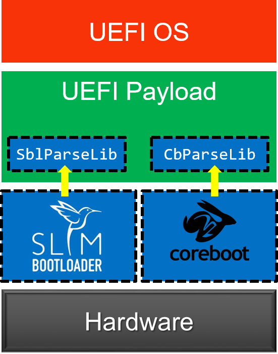
Build and Integration
UEFI payload provides a generic payload for bootloaders to boot UEFI OS. In an ideal case, UEFI payload does not require any customization or any platform porting and can boot on different platforms by consuming the platform information from the bootloader.
Building the UEFI payload is similar to building other EDK II platforms. See BuildAndIntegrationInstructions.txt for more details.
ArmRealViewEbPkg
This package was implementing UEFI support for ARM RealView Emulation Board. This package has moved to ArmPlatformPkg/ArmRealViewEbPkg.
Source Repository
Beagle Board Wiki
Beagle Board
To find the latest instructions to build the BeagleBoard on Linux go to this wikipage
Get the edk2 source tree and build BeagleBoardPkg in Windows® Cygwin Bash shell
The following instructions assume you have the ARM RealView Development Suite v3.1 and Cygwin installed on Windows. Other versions of the RealView Development Suite should work, but only v3.1 and v4.0 have been tested.
If you use the command line version of subversion, then you can easily checkout the edk2 and source to the FAT32 driver to the /cygdrive/c/edk2 directory with the following commands:
/cygdrive/c$ svn co https://edk2.svn.sourceforge.net/svnroot/edk2/trunk/edk2 edk2 --username guest
/cygdrive/c$ cd edk2
/cygdrive/c/edk2$ svn co https://edk2-fatdriver2.svn.sourceforge.net/svnroot/edk2-fatdriver2/trunk/FatPkg FatPkg --username guest
Build the Beagle Board Package Now you can run the build.sh script
/cygdrive/c/edk2$ cd /cygdrive/c/edk2/BeagleBoardPkg
/cygdrive/c/edk2/BeagleBoardPkg$ ./build.sh
As a tangible result of the build, the FLASH image for the Beagle Board will end up in /cygdrive/c/edk2/Build/BeagleBoard/DEBUG_RVCT31CYGWIN/FV/Beagle Board_EFI_flashboot.fd. Note: You may get a build error that looks like:
/bin/sh: /cygdrive/c/Program Files/ARM/RVCT/Programs/3.1/761/win_32-pentium/armcc: No such file or directory
This means your ARM compiler is installed in a different location. You will need to edit edk2/Conf/tools_def.txt to match the location your compiler was installed (search for DEFINE RVCT31CYGWIN_TOOLS_PATH). The tools_def.txt file is created when the ./build.sh script sources . edksetup.sh BaseTools to setup the environment. It is copied from edk2/BaseTools/Conf/tools_def.template that is checked into source control. You can make local edits to the tools_def.txt version and not worry about accidentally checking it in to source control.
The ./build.sh script also supports arguments. If you pass RELEASE debug code is stripped out. Please note the image that gets created is a fixed size Firmware Volume, so setting RELEASE will increase the amount of free space in the file system and not make the image physically smaller. You can also do a clean by passing in clean. DEBUG (default for ./build.sh) and RELEASE builds are built in different directories. All other arguments are passed directly to the edk2 build command. Here are some examples:
/cygdrive/c/edk2/BeagleBoardPkg$ ./build.sh clean
/cygdrive/c/edk2/BeagleBoardPkg$ ./build.sh RELEASE
/cygdrive/c/edk2/BeagleBoardPkg$ ./build.sh RELEASE clean
/cygdrive/c/edk2/BeagleBoardPkg$ ./build.sh -y report.log -v
Get the edk2 source tree and build BeagleBoardPkg Visual Studio .NET 2003 Command Prompt Window
The following instructions assume you have the ARM RealView Development Suite v3.1 and Subversion installed on Windows. Other versions of the RealView Development Suite should work, but only v3.1 and v4.0 have been tested.
If you don't have Cygwin installed you can't use the build.sh Bash script in the BeagleBoardPkg directory. Building on Windows is a little simpler as binary versions of all the tools are checked in.
If you use the command line version of subversion, then you can easily checkout the edk2 to the C:\edk2 directory with the following command:
C:\> svn co https://edk2.svn.sourceforge.net/svnroot/edk2/trunk/edk2 C:\edk2 --username guest
C:\> cd C:\edk2
C:\edk2> svn co https://edk2-fatdriver2.svn.sourceforge.net/svnroot/edk2-fatdriver2/trunk/FatPkg FatPkg --username guest
The b.bat script builds the EFI Beagle Board image, patches the beginning of the image with information needed by the mask ROM, and builds some debug scripts for RealView and Trace32 JTAG debuggers.
C:\> cd C:\edk2\BeagleBoardPkg
C:\edk2\BeagleBoardPkg> b
The b.bat script also supports arguments. If you pass RELEASE debug code is stripped out. Please note the image that gets created is a fixed size Firmware Volume, so setting RELEASE will increase the amount of free space in the file system and not make the image physically smaller. You can also do a clean by passing in clean. DEBUG (default for b.bat) and RELEASE builds are built in different directories. All other arguments are passed directly to the edk2 build command. Here are some examples:
C:\edk2\BeagleBoardPkg> b clean
C:\edk2\BeagleBoardPkg> b RELEASE
C:\edk2\BeagleBoardPkg> b RELEASE clean
C:\edk2\BeagleBoardPkg> b -y report.log -v
Note: You may get a build error that looks like:
NMAKE : fatal error U1077: '"c:/Program Files/ARM/RVCT/Programs/3.1/761/win_32-pentium/armcc"' : return code '0x1'
This means your ARM compiler is installed in a different location. You will need to edit edk2\Conf\tools_def.txt to match the location your compiler was installed (search for DEFINE RVCT31_TOOLS_PATH). The tools_def.txt file is created when the edksetup.bat script ran to setup the environment. It is copied from edk2\BaseTools\Conf\tools_def.template that is checked into source control. You can make local edits to the .txt version and not worry about accidentally checking it in to source control.
Boot EFI from RAM on Beagle Board using RealView Debugger
If you have an RealView Debugger hooked up to your Beagle Board you can use /cygdrive/c/edk2/Build/BeagleBoard/DEBUG_RVCT31CYGWI N/rvi_boot_from_ram.inc to down load the EFI image over JTAG and boot it. To load the script go to the Tools menu and select Include Commands from File... You can use edk2/Build/BeagleBoard/DEBUG_RVCT31CYGWIN/rvi_load_symbols.inc to load symbols for the multiple EFI images in the debugger. Note: Some early versions of the RVI have a bug as the script can not access memory and does not work. You need to load the symbols after you break into the debugger.
When the Beagle Board boots from the NAND FLASH the mask ROM on the Beagle Board executes commands out of the start of the NAND to turn on memory and then copies the image from the NAND into system memory and jumps to it. In the EFI world this NAND image is called an FD (Flash Device) image and it contains 520 bytes of image header for the mask ROM and an FV (Firmware Volume). The FV is a simple FLASH file system and the first 4 bytes of the FV contain a jump to the SEC (SEcuirty Core) module. The SEC is a PE/COFF image that contains the reset vector and it is located in an arbitrary location in the FV. When you boot from JTAG the mask ROM on the Beagle Board does not run and the RVD script copies the FD into system memory and sets the PC to first location in the FV.
If you have the version of the debugger that does not support the rvi_load_symbols.inc script you can do the following to load symbols. Edit the following lines of /cygdrive/c/edk2/BeagleBoardPkg/BeagleBoardPkg.dsc:
# PeCoffExtraActionLib|ArmPkg/Library/RvdPeCoffExtraActionLib/RvdPeCoffExtraActionLib.inf
PeCoffExtraActionLib|MdePkg/Library/BasePeCoffExtraActionLibNull/BasePeCoffExtraActionLibNull.inf
and convert them to:
PeCoffExtraActionLib|ArmPkg/Library/RvdPeCoffExtraActionLib/RvdPeCoffExtraActionLib.inf
# PeCoffExtraActionLib|MdePkg/Library/BasePeCoffExtraActionLibNull/BasePeCoffExtraActionLibNull.inf
This will send a series of commands to the RVD console, via semihosting, that can be used to load symbols. Please note that sending all this data via semihosting slows boot down a lot. After the system gets to the point where you would like to source level debug stop execution on the target. Copy the contents of the StdIO window to a file, and use Tools Include Commands from File... You should now have source level debug for any EFI module that was loaded in memory. The reset vector code exists in the SEC module located in the FV. The SEC was relocated to its execution address by the build tool that constructed the FV. Since this code runs from a fixed address you have to manually load symbols for this code. The SEC loads the DXE Core and that should be the first load command you see in the StdIO window of the debugger. The following is an example of the first prints that come out of the SEC code. You can cut the load command and past it directly into the RVD Cmd window to source level debug the SEC.
UART Enabled
load /a /ni /np c:\work\edk2\Build\BeagleBoard\DEBUG_RVCT31CYGWIN\ARM\BeagleBoardPkg\Sec\Sec\DEBUG\BeagleBoardSec.dll &0x80008360
Put edk2 code in the Beagle Board NAND using U-Boot
The OMAP mask ROM can boot from the MMC/SD card regardless of the state of the NAND (normal boot location). To boot from an SD card it has to be constructed as detailed in Step #1. You then power cycle the Beagle Board (unplug it and plug it back in) while holding down the USER button.
Step #1: Follow the instructions and build an MMC/SD card that boots the Beagle Board U-Boot.
You only need to do the following steps: Prepare MMC/SD card for Validation Copy the following files on to MMC in the following order: When copying files to the SD card make sure you follow the NOTE and copy "Regular script file" as boot.scr. In addition to the above instructions copy edk2\Build\BeagleBoard\DEBUG_RVCT31CYGWIN\FV\BeagleBoar d_EFI_flashboot.fd to MMC/SD card.
Step #2 Place SD card back in Beagle Board power cycle while holding down USER button hit a key on the serial console to stop u-boot from loading Linux
Step #3: At the U-Boot prompt (currently OMAP3 beagleboard.org # ) type the following commands to put the EFI code in the NAND:
OMAP3 beagleboard.org # mmcinit
OMAP3 beagleboard.org # fatload mmc 0 80208000 BeagleBoard_EFI_flashboot.fd
OMAP3 beagleboard.org # nandecc hw
OMAP3 beagleboard.org # nand erase 0 80000
OMAP3 beagleboard.org # nand write 80208000 0 80000
Step #4 Hit the reset button and you should see DEBUG prints from EFI. You should get to the prompt and it will look like:
Embedded Boot Loader (EBL) prototype. Built at 16:18:20 on Dec 9 2009
THE PROGRAM IS DISTRIBUTED UNDER THE BSD LICENSE ON AN 'AS IS' BASIS,
WITHOUT WARRANTIES OR REPRESENTATIONS OF ANY KIND, EITHER EXPRESS OR IMPLIED.
Please send feedback to dev@edk2.tianocore.org
BeagleEdk2>
This works for getting the EFI image in the NAND the 1st time, and is also a way to recover the image if the NAND ever gets into a bad state.
Put edk2 code in the Beagle Board DRAM using U-Boot
See Booting EDK2 in the Beagle Board DRAM using U-Boot
Put edk2 code in the Beagle Board NAND using EBL
Step #1: Copy edk2\Build\BeagleBoard\DEBUG_RVCT31CYGWIN\FV\BeagleBoar d_EFI_flashboot.fd to a MMC/SD card
Step #2: Place SD card back in Beagle Board Boot EFI on the Beagle Board (power cycle if you have it in NAND for example)
Step #3: Use the EFI EBL to flash the image
BeagleEdk2> cp fs1:\Beagle Board_EFI_flashboot.fd blk0:
Beagle Board Boot Flow
The Beagle Board does not implement PEI. SEC loads the DXE core directly. See the PI Boot Flow for an overview of PI booting.
NAND FLASH Layout
The OMAP3530 used on the Beagle Board contains a mask ROM that initiates
the boot process. The image in the NAND FLASH starts with a 512 (0x200)
byte Table of Contents (TOC) and a set of configuration headers. The
mask ROM uses information in the configuration headers to program clocks
and turn on DRAM. After DRAM is initialized the Initial software is
copied from NAND to DRAM. The first 4 bytes of the image contain the
size of the image, and the next 4 bytes contain the address of where the
image should be copied. On the Beagle Board the image is copied to
0x80008208.
 The values used to initialize clocks and DRAM come from the
ConfigurationHeader.dat
text file. The build process uses the
GenerateImage
utility to parse the ConfigurationHeader.dat file and patch the
information required by the OMPA3530 mask ROM into the beginning of the
image.
The values used to initialize clocks and DRAM come from the
ConfigurationHeader.dat
text file. The build process uses the
GenerateImage
utility to parse the ConfigurationHeader.dat file and patch the
information required by the OMPA3530 mask ROM into the beginning of the
image.
The edk2 build process creates a Firmware Device (FD) image that has space reserved for the OMAP3530 configuration headers. In the edk2 the FD layout is controlled by a Flash Description File (.fdf). The Flash Description file for the Beagle Board is called BeagleBoardPkg.fdf. The Beagle Board FD contains 512 (0x200) bytes of OMAP3530 configuration headers followed by 8 bytes of the OMAP3530 image header. The OMAP3530 image header contains the size of the Software Image and the location the image should be loaded in DRAM. For the Beagle Board the Software Image is a Firmware Volume (FV) called FVMAIN_COMPACT. FVMAIN_COMPACT contains two files. The first file is the SEC code that the mask ROM jumps into and the 2nd file is a compressed FV, called FVMAIN. FVMAIN_COMPACT is called fv0 in the EBL shell. You can use the dir command to see the contents of the FV.
BeagleEdk2>dir fv0:
19,800 SEC D959E387-7B91-452C-90E0-A1DBAC90DDB8
99,271 FV 9E21FD93-9C72-4C15-8C4B-E77F1DB2D792
119,071 bytes in files 404,569 bytes free
FVMAIN is called fv1 and this is the decompressed copy of the FV file in fv0:
BeagleEdk2>dir fv1:
44,568 DxeCore D6A2CB7F-6A18-4E2F-B43B-9920A733700A DxeCore
22,100 Driver B8D9777E-D72A-451F-9BDB-BAFB52A68415 ArmCpuDxe
5,062 Driver B601F8C4-43B7-4784-95B1-F4226CB40CEE RuntimeDxe
2,480 Driver F80697E9-7FD6-4665-8646-88E33EF71DFC SecurityStubDxe
1,788 Driver F099D67F-71AE-4C36-B2A3-DCEB0EB2B7D8 WatchdogTimer
3,780 Driver 42857F0A-13F2-4B21-8A23-53D3F714B840 CapsuleRuntimeDxe
6,396 Driver 02B01AD5-7E59-43E8-A6D8-238180613A5A EmuVariableRuntimeDxe
1,378 Driver FCABE6A7-7953-4A84-B7EC-D29E89B62E87 EmbeddedMonotonicCounter
2,492 Driver 6696936D-3637-467C-87CB-14EA8248948C SimpleTextInOutSerial
2,236 Driver 16036A73-E8EF-46D0-953C-9B8E96527D13 Reset
1,260 Driver B336F62D-4135-4A55-AE4E-4971BBF0885D RealTimeClock
1,834 Driver 4C6E0267-C77D-410D-8100-1495911A989D MetronomeDxe
3,102 Driver C5B9C74A-6D72-4719-99AB-C59F199091EB SemihostFs
4,452 Driver 4D00EF14-C4E0-426B-81B7-30A00A14AAD6 NandFlash
4,364 Driver 100C2CFA-B586-4198-9B4C-1683D195B1DA MMCHS
1,724 Driver D5125E0F-1226-444F-A218-0085996ED5DA Smbus
1,402 Driver E7D9CAE1-6930-46E3-BDF9-0027446E7DF2 Gpio
2,144 Driver 23EED05D-1B93-4A1A-8E1B-931D69E37952 BeagleBoardInterruptDxe
2,728 Driver 6DDBF08B-CFC9-43CC-9E81-0784BA312CA0 BeagleBoardTimerDxe
1,490 Driver 71FE861A-5450-48B6-BFB0-B93522616F99 TPS65950
4,156 Driver 6B38F7B4-AD98-40E9-9093-ACA2B5A253C4 DiskIoDxe
8,898 Driver 1FA1F39E-FEFF-4AAE-BD7B-38A070A3B609 PartitionDxe
14,992 Driver 961578FE-B6B7-44C3-AF35-6BC705CD2B1F Fat
2,686 Driver CD3BAFB6-50FB-4FE8-8E4E-AB74D2C1A600 EnglishDxe
3,892 Driver FEAA2E2B-53AC-4D5E-AE10-1EFD5DA4A2BA BeagleBoardPciEmulation
12,056 Driver BDFE430E-8F2A-4DB0-9991-6F856594777E EhciDxe
11,484 Driver 240612B7-A063-11D4-9A3A-0090273FC14D UsbBusDxe
8,268 Driver 9FB4B4A7-42C0-4BCD-8540-9BCC6711F83E UsbMassStorageDxe
44,016 App 3CEF354A-3B7A-4519-AD70-72A134698311 Ebl
7,246 Driver 934431FE-5745-402E-913D-17B4434EB0F3 BeagleBoardBds
234,474 bytes in files 846 bytes free
The edk2 build process places all the .fd and .fv files in the FV directory of the build root. The build root starts in the edk2 directory as Build/BeagleBoard then there is a directory name that contains the Target (DEBUG or RELEASE build), an underscore, and then the target tools type. So for example edk2\Build\BeagleBoard\DEBUG_RVCT31\FV would be the DEBUG build using RVCT 3.1 compiler.
{| border="1" |+ Files Related to the Beagle Board NAND FLASH Image ! File !! Description |- ! BeagleBoard_EFI_flashboot.fd | Final image that can be placed in FLASH or copied to DRAM @ 0x80008000 |- ! BEAGLEBOARD_EFI.fd | Contains FVs, but has not been patched with OMAP3530 configuration headers |- ! FVMAIN_COMPACT.Fv | The Firmware Volume in BEAGLEBOARD_EFI.fd that contains the SEC (reset vector code) and a compressed copy of FVMAIN.Fv |- ! FVMAIN.Fv | Fimrware Volume containing the EFI drivers used for booting |} If you have your shell set up to build the edk2 the VolInfo command should be in your path and you can use it to dump out the contents of a .Fv file.
Reset Vector The OMAP 3530 mask ROM executes first and used the configuration headers found in NAND FLASH Layout to turn on DRAM and shadow the NAND FLASH image into memory at 0x80008208. Address 0x8008208 is the beginning of the FVMAIN_COMPACT.Fv. An FV starts with a EFI_FIRMWARE_VOLUME_HEADER data structure. On the Beagle Board the first 4 bytes of the EFI_FIRMWARE_VOLUME_HEADER.ZeroVector has been patched by a build tool to be a branch to the entry point of the SEC PE/COFF Image.
///
/// Describes the features and layout of the firmware volume.
///
typedef struct {
///
/// The first 16 bytes are reserved to allow for the reset vector of
/// processors whose reset vector is at address 0.
///
UINT8 ZeroVector[16];
///
/// Declares the file system with which the firmware volume is formatted.
///
EFI_GUID FileSystemGuid;
///
/// Length in bytes of the complete firmware volume, including the header.
///
UINT64 FvLength;
///
/// Set to EFI_FVH_SIGNATURE
///
UINT32 Signature;
///
/// Declares capabilities and power-on defaults for the firmware volume.
///
EFI_FVB_ATTRIBUTES_2 Attributes;
///
/// Length in bytes of the complete firmware volume header.
///
UINT16 HeaderLength;
///
/// A 16-bit checksum of the firmware volume header. A valid header sums to zero.
///
UINT16 Checksum;
///
/// Offset, relative to the start of the header, of the extended header
/// (EFI_FIRMWARE_VOLUME_EXT_HEADER) or zero if there is no extended header.
///
UINT16 ExtHeaderOffset;
///
/// This field must always be set to zero.
///
UINT8 Reserved[1];
///
/// Set to 2. Future versions of this specification may define new header fields and will
/// increment the Revision field accordingly.
///
UINT8 Revision;
///
/// An array of run-length encoded FvBlockMapEntry structures. The array is
/// terminated with an entry of {0,0}.
///
EFI_FV_BLOCK_MAP_ENTRY BlockMap[1];
} EFI_FIRMWARE_VOLUME_HEADER;
typedef struct {
///
/// The number of sequential blocks which are of the same size.
///
UINT32 NumBlocks;
///
/// The size of the blocks.
///
UINT32 Length;
} EFI_FV_BLOCK_MAP_ENTRY;
The first line of edk2 source code that is executed is the symbol _ModuleEntryPoint in the SEC. The edk2 has ARMASM compatible assembler files that have a .asm extension, and gcc compatible assembler files that have a .S extension. ModuleEntryPoint.asm and ModuleEntryPoint.S contain _ModuleEntryPoint. The primary job of the SEC is to load the DXE Core. The DXE Core can be thought of as the EFI mini-kernel, as it produces the EFI boot and runtime services as called out in the UEFI specification. The Beagle Board SEC does the following:
- Disable L2
- Enable Alignment checking
- Set CPU vectors to start of DRAM 0x80000000
- Switch to SVC mode, and set up a single stack
- Configure pads for input/output
- Initialize Clocks
- Enable Branch Prediction
- Turn on MMU and caches
- Initialize UART
- Build HOBs needed by DXE Core
- Start free running timer for the timer lib
- Decompress compressed FV
- Boot DXE Core
DXE Dispatch
The DXE Core is for the most part generic code. The DXE core dispatches drivers that add APIs called Protocols to the system. Dispatching involves choosing the order that drivers are loaded. The drivers are PE/COFF images and they are loaded an relocated into free memory, and then control is passed to the driver to run its initialization function. The drivers initialization function does work, registers protocols, and returns to the DXE core so the next driver can be dispatched. The UEFI PI specification introduces the concept of a dependency grammar. The dependency grammar allows a driver to run before or after another driver (not common) or wait for the protocols the driver depends on to be present in the system. The dependency grammar is stack based and contains the following opcodes:
- BEFORE
<File Name GUID> - AFTER
<File Name GUID> - PUSH
- AND
- OR
- NOT
- TRUE
- FALSE
- END
- SOR (Schedule on Request)
A file in an FV consists of multiple sections and a driver will contain a PE/COFF section and an optional dependency section. The dependency section contains the byte codes of the dependency grammar. However, the dependency sections are generated from the [Depex] section of the drivers .inf file. The .inf file is the build control file for the driver. TimerDxe.inf is an example of an .inf file for a driver that depends on the gHardwareInterruptProtocolGuid to be present before it gets dispatched. There are four common dependency expression forms that are used:
- TRUE
- gHardwareInterruptProtocolGuid
- gHardwareInterruptProtocolGuid AND gSecondProtocolGuid
- No Dependency expression
A Dependency expression of TRUE means the driver can dispatched at any time. In practice the DXE core will dispatch any driver who's dependency expression evaluates to true. If multiple drivers evaluate to true the drivers will be loaded in an arbitrary order, usually the order they were found in the FV. Usually drivers will be coded so they depend on one or more protocol being present and the Depex section in the .inf file will contain a set of protocols that are AND'ed together. A driver that contains no dependency expression is a special case. It is not the same as a dependency expression of TRUE. No dependency expression implies that the driver is an EFI driver and depends on all EFI services being present. The PI specification defines protocols, named architectural protocols, that are required by the DXE core to implement the boot and runtime services defined in the UEFI specification. So no dependency expression implies a dependency expression of all the following protocols AND'ed together:
- gEfiSecurityArchProtocolGuid
- gEfiCpuArchProtocolGuid
- gEfiMetronomeArchProtocolGuid
- gEfiTimerArchProtocolGuid
- gEfiBdsArchProtocolGuid
- gEfiWatchdogTimerArchProtocolGuid
- gEfiRuntimeArchProtocolGuid
- gEfiVariableArchProtocolGuid
- gEfiVariableWriteArchProtocolGuid
- gEfiCapsuleArchProtocolGuid
- gEfiMonotonicCounterArchProtocolGuid
- gEfiResetArchProtocolGuid
- gEfiRealTimeClockArchProtocolGuid
The debug prints from a DEBUG build of the Beagle Board show the dispatch order on the Beagle Board:
Loading driver at 0x00087EDA000 EntryPoint=0x00087EDC5F5 RuntimeDxe.efi
Loading driver at 0x00087EB3000 EntryPoint=0x00087EB5081 SecurityStubDxe.efi
Loading driver at 0x00087ED5000 EntryPoint=0x00087ED8F29 EmuVariableRuntimeDxe.efi
Loading driver at 0x00087ED3000 EntryPoint=0x00087ED482D EmbeddedMonotonicCounter.efi
Loading driver at 0x00087EB0000 EntryPoint=0x00087EB1D21 SimpleTextInOutSerial.efi
Loading driver at 0x00087EAD000 EntryPoint=0x00087EAED8D Reset.efi
Loading driver at 0x00087EAB000 EntryPoint=0x00087EAC6DD RealTimeClock.efi
Loading driver at 0x00087EA9000 EntryPoint=0x00087EAA941 MetronomeDxe.efi
Loading driver at 0x00087EA6000 EntryPoint=0x00087EA857D NandFlash.efi
Loading driver at 0x00087EA3000 EntryPoint=0x00087EA4AB1 Smbus.efi
Loading driver at 0x00087EA1000 EntryPoint=0x00087EA28CD Gpio.efi
Loading driver at 0x00087E9E000 EntryPoint=0x00087E9FDC5 BeagleBoardInterruptDxe.efi
Loading driver at 0x00087E9A000 EntryPoint=0x00087E9CE3D BeagleBoardBds.efi
Loading driver at 0x00087E92000 EntryPoint=0x00087E97C29 ArmCpuDxe.efi
Loading driver at 0x00087ED0000 EntryPoint=0x00087ED2109 CapsuleRuntimeDxe.efi
Loading driver at 0x00087E8F000 EntryPoint=0x00087E90C45 BeagleBoardTimerDxe.efi
Loading driver at 0x00087E8C000 EntryPoint=0x00087E8DA11 TPS65950.efi
Loading driver at 0x00087E89000 EntryPoint=0x00087E8A985 WatchdogTimer.efi
Loading driver at 0x00087E85000 EntryPoint=0x00087E87CC5 MMCHS.efi
Loading driver at 0x00087E81000 EntryPoint=0x00087E841B5 BeagleBoardPciEmulation.efi
Loading driver at 0x00087E7D000 EntryPoint=0x00087E7FB1D SemihostFs.efi
Loading driver at 0x00087E7A000 EntryPoint=0x00087E7C531 DiskIoDxe.efi
Loading driver at 0x00087E75000 EntryPoint=0x00087E79599 PartitionDxe.efi
Loading driver at 0x00087E6C000 EntryPoint=0x00087E737B5 Fat.efi
Loading driver at 0x00087E69000 EntryPoint=0x00087E6A9E9 EnglishDxe.efi
Loading driver at 0x00087E61000 EntryPoint=0x00087E67CD5 EhciDxe.efi
Loading driver at 0x00087E58000 EntryPoint=0x00087E5F529 UsbBusDxe.efi
Loading driver at 0x00087E52000 EntryPoint=0x00087E56539 UsbMassStorageDxe.efi
How do I load symbols for debugging
The Beagle Board Boot Flow section describes how UEFI, and especially PI, boot by loading a series of PE/COFF images. A natural question to ask is how load symbols for a debugger, especially when you consider that EFI defaults to load images at arbitrary addresses. Luckily the UEFI specification has a concept know as an EFI Debug Support Table that is defined in section 17.4 of UEFI 2.3 specification. Using the EFI Debug Support Table it is possible to write a debugger script to load symbols. As an example of how to utilize the EFI debug Support Table the Beagle Board port has an extra EBL shell command to dump the symbol table information contained in the EFI Debug Support Table. This extra EBL shell command is called symboltable and the source code can be found in EblCmdLib.c. The symboltable (sync commands can be shortened as long as they are unique, we will use sym as a synonym for symboltable) command parses the EFI Debug Support Table and dumps out a set of commands that can be used with a debugger. The default for sym is to dump out RealView Debugger symbol load commands. The following is an example from a Beagle Board.
BeagleEdk2>sym
load /a /ni /np c:\work\edk2\Build\BeagleBoard\DEBUG_RVCT31\ARM\MdeModulePkg\Core\Dxe\DxeMain\DEBUG\DxeCore.dll & 0x87F2F240 load /a /ni /np c:\work\edk2\Build\BeagleBoard\DEBUG_RVCT31\ARM\MdeModulePkg\Core\RuntimeDxe\RuntimeDxe\DEBUG\RuntimeDxe.dll & 0x87EDA240 load /a /ni /np c:\work\edk2\Build\BeagleBoard\DEBUG_RVCT31\ARM\MdeModulePkg\Universal\SecurityStubDxe\SecurityStubDxe\DEBUG\SecurityStubDxe.dll & 0x87EB3240 load /a /ni /np c:\work\edk2\Build\BeagleBoard\DEBUG_RVCT31\ARM\MdeModulePkg\Universal\Variable\EmuRuntimeDxe\EmuVariableRuntimeDxe\DEBUG\EmuVariableRuntimeDxe.dll & 0x87ED5240 load /a /ni /np c:\work\edk2\Build\BeagleBoard\DEBUG_RVCT31\ARM\EmbeddedPkg\EmbeddedMonotonicCounter\EmbeddedMonotonicCounter\DEBUG\EmbeddedMonotonicCounter.dll & 0x87ED3240 load /a /ni /np c:\work\edk2\Build\BeagleBoard\DEBUG_RVCT31\ARM\EmbeddedPkg\SimpleTextInOutSerial\SimpleTextInOutSerial\DEBUG\SimpleTextInOutSerial.dll & 0x87EB0240 load /a /ni /np c:\work\edk2\Build\BeagleBoard\DEBUG_RVCT31\ARM\EmbeddedPkg\ResetRuntimeDxe\ResetRuntimeDxe\DEBUG\Reset.dll & 0x87EAD240 load /a /ni /np c:\work\edk2\Build\BeagleBoard\DEBUG_RVCT31\ARM\EmbeddedPkg\RealTimeClockRuntimeDxe\RealTimeClockRuntimeDxe\DEBUG\RealTimeClock.dll & 0x87EAB240 load /a /ni /np c:\work\edk2\Build\BeagleBoard\DEBUG_RVCT31\ARM\EmbeddedPkg\MetronomeDxe\MetronomeDxe\DEBUG\MetronomeDxe.dll & 0x87EA9240 load /a /ni /np c:\work\edk2\Build\BeagleBoard\DEBUG_RVCT31\ARM\Omap35xxPkg\Flash\Flash\DEBUG\NandFlash.dll & 0x87EA6240 load /a /ni /np c:\work\edk2\Build\BeagleBoard\DEBUG_RVCT31\ARM\Omap35xxPkg\SmbusDxe\Smbus\DEBUG\Smbus.dll & 0x87EA3240 load /a /ni /np c:\work\edk2\Build\BeagleBoard\DEBUG_RVCT31\ARM\Omap35xxPkg\Gpio\Gpio\DEBUG\Gpio.dll & 0x87EA1240 load /a /ni /np c:\work\edk2\Build\BeagleBoard\DEBUG_RVCT31\ARM\Omap35xxPkg\InterruptDxe\InterruptDxe\DEBUG\BeagleBoardInterruptDxe.dll & 0x87E9E240 load /a /ni /np c:\work\edk2\Build\BeagleBoard\DEBUG_RVCT31\ARM\BeagleBoardPkg\Bds\Bds\DEBUG\BeagleBoardBds.dll & 0x87E9A240 load /a /ni /np c:\work\edk2\Build\BeagleBoard\DEBUG_RVCT31\ARM\ArmPkg\Drivers\CpuDxe\CpuDxe\DEBUG\ArmCpuDxe.dll & 0x87E92240 load /a /ni /np c:\work\edk2\Build\BeagleBoard\DEBUG_RVCT31\ARM\MdeModulePkg\Universal\CapsuleRuntimeDxe\CapsuleRuntimeDxe\DEBUG\CapsuleRuntimeDxe.dll & 0x87ED0240 load /a /ni /np c:\work\edk2\Build\BeagleBoard\DEBUG_RVCT31\ARM\Omap35xxPkg\TimerDxe\TimerDxe\DEBUG\BeagleBoardTimerDxe.dll & 0x87E8F240 load /a /ni /np c:\work\edk2\Build\BeagleBoard\DEBUG_RVCT31\ARM\Omap35xxPkg\TPS65950Dxe\TPS65950\DEBUG\TPS65950.dll & 0x87E8C240 load /a /ni /np c:\work\edk2\Build\BeagleBoard\DEBUG_RVCT31\ARM\MdeModulePkg\Universal\WatchdogTimerDxe\WatchdogTimer\DEBUG\WatchdogTimer.dll & 0x87E89240 load /a /ni /np c:\work\edk2\Build\BeagleBoard\DEBUG_RVCT31\ARM\Omap35xxPkg\MMCHSDxe\MMCHS\DEBUG\MMCHS.dll & 0x87E85240 load /a /ni /np c:\work\edk2\Build\BeagleBoard\DEBUG_RVCT31\ARM\Omap35xxPkg\PciEmulation\PciEmulation\DEBUG\BeagleBoardPciEmulation.dll & 0x87E81240 load /a /ni /np c:\work\edk2\Build\BeagleBoard\DEBUG_RVCT31\ARM\ArmPkg\Filesystem\SemihostFs\SemihostFs\DEBUG\SemihostFs.dll & 0x87E7D240 load /a /ni /np c:\work\edk2\Build\BeagleBoard\DEBUG_RVCT31\ARM\MdeModulePkg\Universal\Disk\DiskIoDxe\DiskIoDxe\DEBUG\DiskIoDxe.dll & 0x87E7A240 load /a /ni /np c:\work\edk2\Build\BeagleBoard\DEBUG_RVCT31\ARM\MdeModulePkg\Universal\Disk\PartitionDxe\PartitionDxe\DEBUG\PartitionDxe.dll & 0x87E75240 load /a /ni /np c:\work\edk2\Build\BeagleBoard\DEBUG_RVCT31\ARM\FatPkg\EnhancedFatDxe\Fat\DEBUG\Fat.dll & 0x87E6C240 load /a /ni /np c:\work\edk2\Build\BeagleBoard\DEBUG_RVCT31\ARM\MdeModulePkg\Universal\Disk\UnicodeCollation\EnglishDxe\EnglishDxe\DEBUG\EnglishDxe.dll & 0x87E69240 load /a /ni /np c:\work\edk2\Build\BeagleBoard\DEBUG_RVCT31\ARM\MdeModulePkg\Bus\Pci\EhciDxe\EhciDxe\DEBUG\EhciDxe.dll & 0x87E61240 load /a /ni /np c:\work\edk2\Build\BeagleBoard\DEBUG_RVCT31\ARM\MdeModulePkg\Bus\Usb\UsbBusDxe\UsbBusDxe\DEBUG\UsbBusDxe.dll & 0x87E58240 load /a /ni /np c:\work\edk2\Build\BeagleBoard\DEBUG_RVCT31\ARM\MdeModulePkg\Bus\Usb\UsbMassStorageDxe\UsbMassStorageDxe\DEBUG\UsbMassStorageDxe.dll & 0x87E52240 load /a /ni /np c:\work\edk2\Build\BeagleBoard\DEBUG_RVCT31\ARM\EmbeddedPkg\Ebl\Ebl\DEBUG\Ebl.dll & 0x87160240
The 1st argument to sym is optional and it can be used to change the template for how the symbol file load commands are printed out. The default string is for the RealView Debugger. The first format specifier in the string must be for an ASCII string for the file name of the symbol file and the second format specifier must be for the load address of the PE/COFF image. The EFI Print routine is not fully compatible with POSIX printf. %a is for an ASCII string, %s is for Unicode, and %x is for a hex number with no leading 0x.
BeagleEdk2>sym "add-symbol-file %a 0x%x"
add-symbol-file c:\work\edk2\Build\BeagleBoard\DEBUG_RVCT31\ARM\MdeModulePkg\Core\Dxe\DxeMain\DEBUG\DxeCore.dll 0x87F2F240 add-symbol-file c:\work\edk2\Build\BeagleBoard\DEBUG_RVCT31\ARM\MdeModulePkg\Core\RuntimeDxe\RuntimeDxe\DEBUG\RuntimeDxe.dll 0x87EDA240 add-symbol-file c:\work\edk2\Build\BeagleBoard\DEBUG_RVCT31\ARM\MdeModulePkg\Universal\SecurityStubDxe\SecurityStubDxe\DEBUG\SecurityStubDxe.dll 0x87EB3240 add-symbol-file c:\work\edk2\Build\BeagleBoard\DEBUG_RVCT31\ARM\MdeModulePkg\Universal\Variable\EmuRuntimeDxe\EmuVariableRuntimeDxe\DEBUG\EmuVariableRuntimeDxe.dll 0x87ED5240 add-symbol-file c:\work\edk2\Build\BeagleBoard\DEBUG_RVCT31\ARM\EmbeddedPkg\EmbeddedMonotonicCounter\EmbeddedMonotonicCounter\DEBUG\EmbeddedMonotonicCounter.dll 0x87ED3240 add-symbol-file c:\work\edk2\Build\BeagleBoard\DEBUG_RVCT31\ARM\EmbeddedPkg\SimpleTextInOutSerial\SimpleTextInOutSerial\DEBUG\SimpleTextInOutSerial.dll 0x87EB0240 add-symbol-file c:\work\edk2\Build\BeagleBoard\DEBUG_RVCT31\ARM\EmbeddedPkg\ResetRuntimeDxe\ResetRuntimeDxe\DEBUG\Reset.dll 0x87EAD240 add-symbol-file c:\work\edk2\Build\BeagleBoard\DEBUG_RVCT31\ARM\EmbeddedPkg\RealTimeClockRuntimeDxe\RealTimeClockRuntimeDxe\DEBUG\RealTimeClock.dll 0x87EAB240 add-symbol-file c:\work\edk2\Build\BeagleBoard\DEBUG_RVCT31\ARM\EmbeddedPkg\MetronomeDxe\MetronomeDxe\DEBUG\MetronomeDxe.dll 0x87EA9240 add-symbol-file c:\work\edk2\Build\BeagleBoard\DEBUG_RVCT31\ARM\Omap35xxPkg\Flash\Flash\DEBUG\NandFlash.dll 0x87EA6240 add-symbol-file c:\work\edk2\Build\BeagleBoard\DEBUG_RVCT31\ARM\Omap35xxPkg\SmbusDxe\Smbus\DEBUG\Smbus.dll 0x87EA3240 add-symbol-file c:\work\edk2\Build\BeagleBoard\DEBUG_RVCT31\ARM\Omap35xxPkg\Gpio\Gpio\DEBUG\Gpio.dll 0x87EA1240 add-symbol-file c:\work\edk2\Build\BeagleBoard\DEBUG_RVCT31\ARM\Omap35xxPkg\InterruptDxe\InterruptDxe\DEBUG\BeagleBoardInterruptDxe.dll 0x87E9E240 add-symbol-file c:\work\edk2\Build\BeagleBoard\DEBUG_RVCT31\ARM\BeagleBoardPkg\Bds\Bds\DEBUG\BeagleBoardBds.dll 0x87E9A240 add-symbol-file c:\work\edk2\Build\BeagleBoard\DEBUG_RVCT31\ARM\ArmPkg\Drivers\CpuDxe\CpuDxe\DEBUG\ArmCpuDxe.dll 0x87E92240 add-symbol-file c:\work\edk2\Build\BeagleBoard\DEBUG_RVCT31\ARM\MdeModulePkg\Universal\CapsuleRuntimeDxe\CapsuleRuntimeDxe\DEBUG\CapsuleRuntimeDxe.dll 0x87ED0240 add-symbol-file c:\work\edk2\Build\BeagleBoard\DEBUG_RVCT31\ARM\Omap35xxPkg\TimerDxe\TimerDxe\DEBUG\BeagleBoardTimerDxe.dll 0x87E8F240 add-symbol-file c:\work\edk2\Build\BeagleBoard\DEBUG_RVCT31\ARM\Omap35xxPkg\TPS65950Dxe\TPS65950\DEBUG\TPS65950.dll 0x87E8C240 add-symbol-file c:\work\edk2\Build\BeagleBoard\DEBUG_RVCT31\ARM\MdeModulePkg\Universal\WatchdogTimerDxe\WatchdogTimer\DEBUG\WatchdogTimer.dll 0x87E89240 add-symbol-file c:\work\edk2\Build\BeagleBoard\DEBUG_RVCT31\ARM\Omap35xxPkg\MMCHSDxe\MMCHS\DEBUG\MMCHS.dll 0x87E85240 add-symbol-file c:\work\edk2\Build\BeagleBoard\DEBUG_RVCT31\ARM\Omap35xxPkg\PciEmulation\PciEmulation\DEBUG\BeagleBoardPciEmulation.dll 0x87E81240 add-symbol-file c:\work\edk2\Build\BeagleBoard\DEBUG_RVCT31\ARM\ArmPkg\Filesystem\SemihostFs\SemihostFs\DEBUG\SemihostFs.dll 0x87E7D240 add-symbol-file c:\work\edk2\Build\BeagleBoard\DEBUG_RVCT31\ARM\MdeModulePkg\Universal\Disk\DiskIoDxe\DiskIoDxe\DEBUG\DiskIoDxe.dll 0x87E7A240 add-symbol-file c:\work\edk2\Build\BeagleBoard\DEBUG_RVCT31\ARM\MdeModulePkg\Universal\Disk\PartitionDxe\PartitionDxe\DEBUG\PartitionDxe.dll 0x87E75240 add-symbol-file c:\work\edk2\Build\BeagleBoard\DEBUG_RVCT31\ARM\FatPkg\EnhancedFatDxe\Fat\DEBUG\Fat.dll 0x87E6C240 add-symbol-file c:\work\edk2\Build\BeagleBoard\DEBUG_RVCT31\ARM\MdeModulePkg\Universal\Disk\UnicodeCollation\EnglishDxe\EnglishDxe\DEBUG\EnglishDxe.dll 0x87E69240 add-symbol-file c:\work\edk2\Build\BeagleBoard\DEBUG_RVCT31\ARM\MdeModulePkg\Bus\Pci\EhciDxe\EhciDxe\DEBUG\EhciDxe.dll 0x87E61240 add-symbol-file c:\work\edk2\Build\BeagleBoard\DEBUG_RVCT31\ARM\MdeModulePkg\Bus\Usb\UsbBusDxe\UsbBusDxe\DEBUG\UsbBusDxe.dll 0x87E58240 add-symbol-file c:\work\edk2\Build\BeagleBoard\DEBUG_RVCT31\ARM\MdeModulePkg\Bus\Usb\UsbMassStorageDxe\UsbMassStorageDxe\DEBUG\UsbMassStorageDxe.dll 0x87E52240 add-symbol-file c:\work\edk2\Build\BeagleBoard\DEBUG_RVCT31\ARM\EmbeddedPkg\Ebl\Ebl\DEBUG\Ebl.dll 0x87160240
The 2nd argument to sym is optional and it defines the image type represented by the file name string. The image loaded and relocated in system memory will always be a PE/COFF image as called out in the UEFI specification, but the symbol files can be in different formats. If the compiler produces an ELF or Mach-O image the edk2 build system converts it to a PE/COFF image. The original ELF or Mach-O contain the symbolic debug information and this is what the debugger needs to load. In both ELF and Mach-O images the image header is not loaded into system memory, but it is for PE/COFF. This means the PE/COFF image loaded into system memory starts with a PE/COFF header. The original ELF or Mach-O file, that contains the symbols for debug, does not contain a PE/COFF (or any other) header in the linked image so when we tell the debugger about the location the ELF or Mach-O image was loaded we need to add in the size of the PE/COFF header. The default for the sym command is to add in the size of the PE/COFF header to the image load address, luckily the size of the PE/COFF header is a field in the PE/COFF header so it is easy to calculate. If a 2nd argument is present the size of the PE/COFF header is not added in and as you see below you get the actually load address of the PE/COFF image. As you can see in these two examples the size of the PE/COFF header is 0x240.
BeagleEdk2>sym "add-symbol-file %a 0x%x" PECOFF
add-symbol-file c:\work\edk2\Build\BeagleBoard\DEBUG_RVCT31\ARM\MdeModulePkg\Core\Dxe\DxeMain\DEBUG\DxeCore.dll 0x87F2F000 add-symbol-file c:\work\edk2\Build\BeagleBoard\DEBUG_RVCT31\ARM\MdeModulePkg\Core\RuntimeDxe\RuntimeDxe\DEBUG\RuntimeDxe.dll 0x87EDA000 add-symbol-file c:\work\edk2\Build\BeagleBoard\DEBUG_RVCT31\ARM\MdeModulePkg\Universal\SecurityStubDxe\SecurityStubDxe\DEBUG\SecurityStubDxe.dll 0x87EB3000 add-symbol-file c:\work\edk2\Build\BeagleBoard\DEBUG_RVCT31\ARM\MdeModulePkg\Universal\Variable\EmuRuntimeDxe\EmuVariableRuntimeDxe\DEBUG\EmuVariableRuntimeDxe.dll 0x87ED5000 add-symbol-file c:\work\edk2\Build\BeagleBoard\DEBUG_RVCT31\ARM\EmbeddedPkg\EmbeddedMonotonicCounter\EmbeddedMonotonicCounter\DEBUG\EmbeddedMonotonicCounter.dll 0x87ED3000 add-symbol-file c:\work\edk2\Build\BeagleBoard\DEBUG_RVCT31\ARM\EmbeddedPkg\SimpleTextInOutSerial\SimpleTextInOutSerial\DEBUG\SimpleTextInOutSerial.dll 0x87EB0000 add-symbol-file c:\work\edk2\Build\BeagleBoard\DEBUG_RVCT31\ARM\EmbeddedPkg\ResetRuntimeDxe\ResetRuntimeDxe\DEBUG\Reset.dll 0x87EAD000 add-symbol-file c:\work\edk2\Build\BeagleBoard\DEBUG_RVCT31\ARM\EmbeddedPkg\RealTimeClockRuntimeDxe\RealTimeClockRuntimeDxe\DEBUG\RealTimeClock.dll 0x87EAB000 add-symbol-file c:\work\edk2\Build\BeagleBoard\DEBUG_RVCT31\ARM\EmbeddedPkg\MetronomeDxe\MetronomeDxe\DEBUG\MetronomeDxe.dll 0x87EA9000 add-symbol-file c:\work\edk2\Build\BeagleBoard\DEBUG_RVCT31\ARM\Omap35xxPkg\Flash\Flash\DEBUG\NandFlash.dll 0x87EA6000 add-symbol-file c:\work\edk2\Build\BeagleBoard\DEBUG_RVCT31\ARM\Omap35xxPkg\SmbusDxe\Smbus\DEBUG\Smbus.dll 0x87EA3000 add-symbol-file c:\work\edk2\Build\BeagleBoard\DEBUG_RVCT31\ARM\Omap35xxPkg\Gpio\Gpio\DEBUG\Gpio.dll 0x87EA1000 add-symbol-file c:\work\edk2\Build\BeagleBoard\DEBUG_RVCT31\ARM\Omap35xxPkg\InterruptDxe\InterruptDxe\DEBUG\BeagleBoardInterruptDxe.dll 0x87E9E000 add-symbol-file c:\work\edk2\Build\BeagleBoard\DEBUG_RVCT31\ARM\BeagleBoardPkg\Bds\Bds\DEBUG\BeagleBoardBds.dll 0x87E9A000 add-symbol-file c:\work\edk2\Build\BeagleBoard\DEBUG_RVCT31\ARM\ArmPkg\Drivers\CpuDxe\CpuDxe\DEBUG\ArmCpuDxe.dll 0x87E92000 add-symbol-file c:\work\edk2\Build\BeagleBoard\DEBUG_RVCT31\ARM\MdeModulePkg\Universal\CapsuleRuntimeDxe\CapsuleRuntimeDxe\DEBUG\CapsuleRuntimeDxe.dll 0x87ED0000 add-symbol-file c:\work\edk2\Build\BeagleBoard\DEBUG_RVCT31\ARM\Omap35xxPkg\TimerDxe\TimerDxe\DEBUG\BeagleBoardTimerDxe.dll 0x87E8F000 add-symbol-file c:\work\edk2\Build\BeagleBoard\DEBUG_RVCT31\ARM\Omap35xxPkg\TPS65950Dxe\TPS65950\DEBUG\TPS65950.dll 0x87E8C000 add-symbol-file c:\work\edk2\Build\BeagleBoard\DEBUG_RVCT31\ARM\MdeModulePkg\Universal\WatchdogTimerDxe\WatchdogTimer\DEBUG\WatchdogTimer.dll 0x87E89000 add-symbol-file c:\work\edk2\Build\BeagleBoard\DEBUG_RVCT31\ARM\Omap35xxPkg\MMCHSDxe\MMCHS\DEBUG\MMCHS.dll 0x87E85000 add-symbol-file c:\work\edk2\Build\BeagleBoard\DEBUG_RVCT31\ARM\Omap35xxPkg\PciEmulation\PciEmulation\DEBUG\BeagleBoardPciEmulation.dll 0x87E81000 add-symbol-file c:\work\edk2\Build\BeagleBoard\DEBUG_RVCT31\ARM\ArmPkg\Filesystem\SemihostFs\SemihostFs\DEBUG\SemihostFs.dll 0x87E7D000 add-symbol-file c:\work\edk2\Build\BeagleBoard\DEBUG_RVCT31\ARM\MdeModulePkg\Universal\Disk\DiskIoDxe\DiskIoDxe\DEBUG\DiskIoDxe.dll 0x87E7A000 add-symbol-file c:\work\edk2\Build\BeagleBoard\DEBUG_RVCT31\ARM\MdeModulePkg\Universal\Disk\PartitionDxe\PartitionDxe\DEBUG\PartitionDxe.dll 0x87E75000 add-symbol-file c:\work\edk2\Build\BeagleBoard\DEBUG_RVCT31\ARM\FatPkg\EnhancedFatDxe\Fat\DEBUG\Fat.dll 0x87E6C000 add-symbol-file c:\work\edk2\Build\BeagleBoard\DEBUG_RVCT31\ARM\MdeModulePkg\Universal\Disk\UnicodeCollation\EnglishDxe\EnglishDxe\DEBUG\EnglishDxe.dll 0x87E69000 add-symbol-file c:\work\edk2\Build\BeagleBoard\DEBUG_RVCT31\ARM\MdeModulePkg\Bus\Pci\EhciDxe\EhciDxe\DEBUG\EhciDxe.dll 0x87E61000 add-symbol-file c:\work\edk2\Build\BeagleBoard\DEBUG_RVCT31\ARM\MdeModulePkg\Bus\Usb\UsbBusDxe\UsbBusDxe\DEBUG\UsbBusDxe.dll 0x87E58000 add-symbol-file c:\work\edk2\Build\BeagleBoard\DEBUG_RVCT31\ARM\MdeModulePkg\Bus\Usb\UsbMassStorageDxe\UsbMassStorageDxe\DEBUG\UsbMassStorageDxe.dll 0x87E52000 add-symbol-file c:\work\edk2\Build\BeagleBoard\DEBUG_RVCT31\ARM\EmbeddedPkg\Ebl\Ebl\DEBUG\Ebl.dll 0x87160000
Please note the three sym examples are from the same system that was built using the ARM RVCT 3.1 compiler. The only difference is the arguments used to the sym command. The 2nd option does not do any checking for type of the symbol file it just adjusts the load address.
How do I port a new SoC to the edk2
How do I write an edk2 driver
What is a Library Class vs. a Library Instance
What is a PCD
If you add -y PCD.log -Y PCD to the build command a log file, PCD.log, will be created relative to the workspace (usually the edk2 directory). The following is the first section of the PCD.log file:
===============================================================================
Platform Configuration Database Report
===============================================================================
*P - Platform scoped PCD override in DSC file
*F - Platform scoped PCD override in FDF file
*M - Module scoped PCD override in DSC file
*C - Library has a constructor
*D - Library has a destructor
*CD - Library has both a constructor and a destructor
===============================================================================
===============================================================================
PLATFORM: c:\work\edk2\BeagleBoardPkg\BeagleBoardPkg.dsc
===============================================================================
gArmTokenSpaceGuid
PcdCpuDxeProduceDebugSupport : FLAG (BOOLEAN) = FALSE
PcdArmCacheOperationThreshold : FIXED (UINT32) = 1024
*P PcdCpuVectorBaseAddress : FIXED (UINT32) = 0x80000000
DEC DEFAULT = 0xfff00000
*P PcdCpuResetAddress : FIXED (UINT32) = 0x80008000
DEC DEFAULT = 0x00000000
gEfiMdePkgTokenSpaceGuid
PcdVerifyNodeInList : FLAG (BOOLEAN) = FALSE
PcdUgaConsumeSupport : FLAG (BOOLEAN) = TRUE
PcdUartDefaultBaudRate : FIXED (UINT64) = 115200
PcdMaximumLinkedListLength : FIXED (UINT32) = 1000000
PcdMaximumGuidedExtractHandler : FIXED (UINT32) = 0x10
PcdMaximumAsciiStringLength : FIXED (UINT32) = 1000000
*M EhciDxe.inf = 0x800fffff
PcdMaximumUnicodeStringLength : FIXED (UINT32) = 1000000
PcdDebugClearMemoryValue : FIXED (UINT8) = 0xAF
PcdUefiLibMaxPrintBufferSize : FIXED (UINT32) = 320
PcdPerformanceLibraryPropertyMask : FIXED (UINT8) = 0
PcdUartDefaultStopBits : FIXED (UINT8) = 1
PcdUartDefaultDataBits : FIXED (UINT8) = 8
PcdUartDefaultParity : FIXED (UINT8) = 1
PcdUefiVariableDefaultPlatformLang : FIXED (VOID*) = "en-US"
PcdUefiVariableDefaultLang : FIXED (VOID*) = "eng"
gEfiMdeModulePkgTokenSpaceGuid
PcdFrameworkCompatibilitySupport : FLAG (BOOLEAN) = FALSE
PcdSupportUpdateCapsuleReset : FLAG (BOOLEAN) = FALSE
PcdVariableCollectStatistics : FLAG (BOOLEAN) = FALSE
PcdUnicodeCollationSupport : FLAG (BOOLEAN) = TRUE
PcdUnicodeCollation2Support : FLAG (BOOLEAN) = TRUE
PcdTurnOffUsbLegacySupport : FLAG (BOOLEAN) = FALSE
PcdLoadModuleAtFixAddressEnable : FIXED (UINT64) = 0
PcdMaxSizePopulateCapsule : FIXED (UINT32) = 0x6400000
PcdMaxSizeNonPopulateCapsule : FIXED (UINT32) = 0xa00000
PcdHwErrStorageSize : FIXED (UINT32) = 0x0000
PcdMaxVariableSize : FIXED (UINT32) = 0x400
PcdEmuVariableNvStoreReserved : FIXED (UINT64) = 0
PcdMaxHardwareErrorVariableSize : FIXED (UINT32) = 0x8000
PcdVariableStoreSize : FIXED (UINT32) = 0x10000
PcdLoadFixAddressBootTimeCodePageNumber : PATCH (UINT32) = 0
PcdLoadFixAddressRuntimeCodePageNumber : PATCH (UINT32) = 0
gEmbeddedTokenSpaceGuid
*P PcdCacheEnable : FLAG (BOOLEAN) = TRUE
DEC DEFAULT = FALSE
*P PcdPrePiProduceMemoryTypeInformationHob : FLAG (BOOLEAN) = TRUE
DEC DEFAULT = FALSE
PcdEmbeddedDirCmd : FLAG (BOOLEAN) = TRUE
*P PcdEmbeddedMacBoot : FLAG (BOOLEAN) = TRUE
DEC DEFAULT = FALSE
PcdEmbeddedIoEnable : FLAG (BOOLEAN) = FALSE
PcdEmbeddedHwDebugCmd : FLAG (BOOLEAN) = TRUE
PcdEmbeddedHobCmd : FLAG (BOOLEAN) = TRUE
PcdEmbeddedScriptCmd : FLAG (BOOLEAN) = FALSE
*P PcdEmbeddedPciDebugCmd : FLAG (BOOLEAN) = TRUE
DEC DEFAULT = FALSE
PcdGdbSerial : FLAG (BOOLEAN) = FALSE
*F PcdEmbeddedFdSize : FIXED (UINT32) = 0x00080000
DEC DEFAULT = 0x0000000
*F PcdEmbeddedFdBaseAddress : FIXED (UINT32) = 0x80008000
DEC DEFAULT = 0xffff0000
*F PcdFlashFvMainSize : FIXED (UINT32) = 0x0007FDF8
DEC DEFAULT = 0x0
PcdPrePiStackSize : FIXED (UINT32) = 0x20000
*P PcdPrePiStackBase : FIXED (UINT32) = 0x87FE0000
DEC DEFAULT = 0
*F PcdFlashFvMainBase : FIXED (UINT32) = 0x80008208
DEC DEFAULT = 0x0
PcdPrePiTempMemorySize : FIXED (UINT32) = 0
PcdMemoryTypeEfiACPIReclaimMemory : FIXED (UINT32) = 0
PcdMemoryTypeEfiACPIMemoryNVS : FIXED (UINT32) = 0
PcdMemoryTypeEfiReservedMemoryType : FIXED (UINT32) = 0
*P PcdMemoryTypeEfiRuntimeServicesCode : FIXED (UINT32) = 40
DEC DEFAULT = 0
*P PcdMemoryTypeEfiBootServicesData : FIXED (UINT32) = 3000
DEC DEFAULT = 0
*P PcdMemoryTypeEfiLoaderCode : FIXED (UINT32) = 10
DEC DEFAULT = 0
PcdPrePiBfvBaseAddress : FIXED (UINT32) = 0
PcdPrePiBfvSize : FIXED (UINT32) = 0
*P PcdMemoryTypeEfiRuntimeServicesData : FIXED (UINT32) = 80
DEC DEFAULT = 0
*P PcdPrePiHobBase : FIXED (UINT32) = 0x80001000
DEC DEFAULT = 131072
PcdMemoryTypeEfiLoaderData : FIXED (UINT32) = 0
PcdPrePiCpuMemorySize : FIXED (UINT8) = 32
*P PcdMemoryTypeEfiBootServicesCode : FIXED (UINT32) = 400
DEC DEFAULT = 0
PcdPrePiCpuIoSize : FIXED (UINT8) = 0
PcdEmbeddedPerformanceCounterFreqencyInHz : FIXED (UINT64) = 0x0000000
*P PcdEmbeddedFdPerformanceCounterPeriodInNanoseconds : FIXED (UINT32) = 77
DEC DEFAULT = 0x0000000
PcdInterruptBaseAddress : FIXED (UINT32) = 0x38e00000
PcdTimerPeriod : FIXED (UINT32) = 100000
*P PcdEmbeddedAutomaticBootCommand : FIXED (VOID*) = ""
DEC DEFAULT = L""
*P PcdEmbeddedPrompt : FIXED (VOID*) = "BeagleEdk2"
DEC DEFAULT = "Ebl"
PcdEmbeddedShellCharacterEcho : FIXED (BOOLEAN) = TRUE
PcdEmbeddedDefaultTextColor : FIXED (UINT32) = 0x07
PcdEmbeddedMemVariableStoreSize : FIXED (UINT32) = 0x10000
PcdGdbMaxPacketRetryCount : FIXED (UINT32) = 10000000
gOmap35xxTokenSpaceGuid
PcdBeagleConsoleUart : FIXED (UINT32) = 3
PcdBeagleBoardIRAMFullSize : FIXED (UINT32) = 0x00000000
PcdBeagleFreeTimer : FIXED (UINT32) = 4
PcdBeagleGpmcOffset : FIXED (UINT32) = 0x00000000
PcdBeagleMMCHS1Base : FIXED (UINT32) = 0x00000000
PcdBeagleArchTimer : FIXED (UINT32) = 3
===============================================================================
===============================================================================
...
What is UEFI PI
The UEFI PI specification utilizes some EFI concepts to define how to build modular chunks of code in various phases of the firmwares boot flow. Please see the UEFI and PI Wiki for more information.
Beagleboardpage
Beagle Board
To find the latest instructions to build the BeagleBoard on Linux, see BeagleBoardPkg.
Get the edk2 source tree and build BeagleBoardPkg in Windows® Cygwin Bash shell
The following instructions assume you have the ARM RealView Development Suite v3.1 and Cygwin installed on Windows. Other versions of the RealView Development Suite should work, but only v3.1 and v4.0 have been tested.
If you use the command line version of subversion, then you can easily checkout the edk2 and source to the FAT32 driver to the /cygdrive/c/edk2 directory with the following commands:
/cygdrive/c$ svn co https://edk2.svn.sourceforge.net/svnroot/edk2/trunk/edk2 edk2 --username guest
/cygdrive/c$ cd edk2
/cygdrive/c/edk2$ svn co https://edk2-fatdriver2.svn.sourceforge.net/svnroot/edk2-fatdriver2/trunk/FatPkg FatPkg --username guest
Build the Beagle Board Package Now you can run the build.sh script
/cygdrive/c/edk2$ cd /cygdrive/c/edk2/BeagleBoardPkg
/cygdrive/c/edk2/BeagleBoardPkg$ ./build.sh
As a tangible result of the build, the FLASH image for the Beagle Board will end up in /cygdrive/c/edk2/Build/BeagleBoard/DEBUG_RVCT31CYGWIN/FV/Beagle Board_EFI _flashboot.fd. Note: You may get a build error that looks like:
/bin/sh: /cygdrive/c/Program Files/ARM/RVCT/Programs/3.1/761/win_32-pentium/armcc: No such file or directory
This means your ARM compiler is installed in a different location. You will need to edit edk2/Conf/tools_def.txt to match the location your compiler was installed (search for DEFINE RVCT31CYGWIN_TOOLS_PATH). The tools_def.txt file is created when the ./build.sh script sources . edksetup.sh BaseTools to setup the environment. It is copied from edk2/BaseTools/Conf/tools_def.template that is checked into source control. You can make local edits to the tools_def.txt version and not worry about accidentally checking it in to source control.
The ./build.sh script also supports arguments. If you pass RELEASE debug code is stripped out. Please note the image that gets created is a fixed size Firmware Volume, so setting RELEASE will increase the amount of free space in the file system and not make the image physically smaller. You can also do a clean by passing in clean. DEBUG (default for ./build.sh) and RELEASE builds are built in different directories. All other arguments are passed directly to the edk2 build command. Here are some examples:
/cygdrive/c/edk2/BeagleBoardPkg$ ./build.sh clean
/cygdrive/c/edk2/BeagleBoardPkg$ ./build.sh RELEASE
/cygdrive/c/edk2/BeagleBoardPkg$ ./build.sh RELEASE clean
/cygdrive/c/edk2/BeagleBoardPkg$ -y report.log -v
Boot EFI from RAM on Beagle Board using RealView Debugger
If you have an RealView Debugger hooked up to your Beagle Board you can use /cygdrive/c/edk2/Build/BeagleBoard/DEBUG_RVCT31CYGWI N/rvi_boot_from_ram.inc to down load the EFI image over JTAG and boot it. To load the script go to the Tools menu and select Include Commands from File... You can use edk2/Build/BeagleBoard/DEBUG_RVCT31CYGWIN/rvi_load_symbols.inc to load symbols for the multiple EFI images in the debugger. Note: Some early versions of the RVI have a bug as the script can not access memory and does not work. You need to load the symbols after you break into the debugger.
When the Beagle Board boots from the NAND FLASH the mask ROM on the Beagle Board executes commands out of the start of the NAND to turn on memory and then copies the image from the NAND into system memory and jumps to it. In the EFI world this NAND image is called an FD (Flash Device) image and it contains 520 bytes of image header for the mask ROM and an FV (Firmware Volume). The FV is a simple FLASH file system and the first 4 bytes of the FV contain a jump to the SEC (SEcuirty Core) module. The SEC is a PE/COFF image that contains the reset vector and it is located in an arbitrary location in the FV. When you boot from JTAG the mask ROM on the Beagle Board does not run and the RVD script copies the FD into system memory and sets the PC to first location in the FV.
If you have the version of the debugger that does not support the rvi_load_symbols.inc script you can do the following to load symbols. Edit the following lines of /cygdrive/c/edk2/BeagleBoardPkg/BeagleBoardPkg.dsc:
# PeCoffExtraActionLib|ArmPkg/Library/RvdPeCoffExtraActionLib/RvdPeCoffExtraActionLib.inf
PeCoffExtraActionLib|MdePkg/Library/BasePeCoffExtraActionLibNull/BasePeCoffExtraActionLibNull.inf
and convert them to:
PeCoffExtraActionLib|ArmPkg/Library/RvdPeCoffExtraActionLib/RvdPeCoffExtraActionLib.inf
# PeCoffExtraActionLib|MdePkg/Library/BasePeCoffExtraActionLibNull/BasePeCoffExtraActionLibNull.inf
This will send a series of commands to the RVD console, via semihosting, that can be used to load symbols. Please note that sending all this data via semihosting slows boot down a lot. After the system gets to the point where you would like to source level debug stop execution on the target. Copy the contents of the StdIO window to a file, and use Tools Include Commands from File... You should now have source level debug for any EFI module that was loaded in memory. The reset vector code exists in the SEC module located in the FV. The SEC was relocated to its execution address by the build tool that constructed the FV. Since this code runs from a fixed address you have to manually load symbols for this code. The SEC loads the DXE Core and that should be the first load command you see in the StdIO window of the debugger. The following is an example of the first prints that come out of the SEC code. You can cut the load command and past it directly into the RVD Cmd window to source level debug the SEC.
UART Enabled
load /a /ni /np c:\work\edk2\Build\BeagleBoard\DEBUG_RVCT31CYGWIN\ARM\BeagleBoardPkg\Sec\Sec\DEBUG\BeagleBoardSec.dll &0x80008360
Put edk2 code in the Beagle Board NAND using U-Boot
The OMAP mask ROM can boot from the MMC/SD card regardless of the state of the NAND (normal boot location). To boot from an SD card it has to be constructed as detailed in Step #1. You then power cycle the Beagle Board (unplug it and plug it back in) while holding down the USER button.
Step #1: Follow the instructions and build an MMC/SD card that boots the Beagle Board U-Boot.
You only need to do the following steps: Prepare MMC/SD card for Validation Copy the following files on to MMC in the following order: When copying files to the SD card make sure you follow the NOTE and copy "Regular script file" as boot.scr. In addition to the above instructions copy edk2\Build\BeagleBoard\DEBUG_RVCT31CYGWIN\FV\BeagleBoar d_EFI_flashboot.fd to MMC/SD card.
Step #2 Place SD card back in Beagle Board power cycle while holding down USER button hit a key on the serial console to stop u-boot from loading Linux
Step #3: At the U-Boot prompt (currently OMAP3 beagleboard.org # ) type the following commands to put the EFI code in the NAND:
OMAP3 beagleboard.org # mmcinit
OMAP3 beagleboard.org # fatload mmc 0 80200000 BeagleBoard_EFI_flashboot.fd
OMAP3 beagleboard.org # nandecc hw
OMAP3 beagleboard.org # nand erase 0 80000
OMAP3 beagleboard.org # nand write 80200000 0 80000
Step #4 Hit the reset button and you should see DEBUG prints from EFI. You should get to the prompt and it will look like:
Embedded Boot Loader (EBL) prototype. Built at 16:18:20 on Dec 9 2009
THE PROGRAM IS DISTRIBUTED UNDER THE BSD LICENSE ON AN 'AS IS' BASIS,
WITHOUT WARRANTIES OR REPRESENTATIONS OF ANY KIND, EITHER EXPRESS OR IMPLIED.
Please send feedback to dev@edk2.tianocore.org
BeagleEdk2>
This works for getting the EFI image in the NAND the 1st time, and is also a way to recover the image if the NAND ever gets into a bad state.
Put edk2 code in the Beagle Board DRAM using U-Boot
If we modify the target address of the EFI image it is possible to boot it on top of U-Boot. This is a useful way to do development so you can test your EFI image before you place it in NAND.
Step #1 We need to modify target address of the EFI image to boot it on top of u-boot. In edk2/BeagleBoardPkg/BeagleBoardPkg.fdf change:
####BaseAddress = 0x80208000|gEmbeddedTokenSpaceGuid.PcdEmbeddedFdBaseAddress #The base address of the FLASH Device.
BaseAddress = 0x80008000|gEmbeddedTokenSpaceGuid.PcdEmbeddedFdBaseAddress #The base address of the FLASH Device.
To:
BaseAddress = 0x80208000|gEmbeddedTokenSpaceGuid.PcdEmbeddedFdBaseAddress #The base address of the FLASH Device.
####BaseAddress = 0x80008000|gEmbeddedTokenSpaceGuid.PcdEmbeddedFdBaseAddress #The base address of the FLASH Device.
Step #2 Then rebuild:
/cygdrive/c/edk2$ cd /cygdrive/c/edk2/BeagleBoardPkg
/cygdrive/c/edk2$ ./build.sh
Step #3 Copy edk2\Build\BeagleBoard\DEBUG_RVCT31CYGWIN\FV\BeagleBoard_EFI_flashboot.fd to a MMC/SD card. Note: this path includes the name of the compiler, so if you use a different one, it may be slightly different. Place SD card back in Beagle Board power cycle while holding down USER button hit a key on the serial console to stop u-boot from loading Linux
Step #4 At the prompt (currently OMAP3 beagleboard.org # ) type these following u-boot commands to boot EFI code from DRAM:
OMAP3 beagleboard.org # mmcinit
OMAP3 beagleboard.org # fatload mmc 0 80200000 BeagleBoard_EFI_flashboot.fd
OMAP3 beagleboard.org # go 80208208'
You should see DEBUG prints from EFI, and when you get to the prompt it will look like this:
Embedded Boot Loader (EBL) prototype. Built at 16:18:20 on Dec 9 2009
THE PROGRAM IS DISTRIBUTED UNDER THE BSD LICENSE ON AN 'AS IS' BASIS,
WITHOUT WARRANTIES OR REPRESENTATIONS OF ANY KIND, EITHER EXPRESS OR IMPLIED.
Please send feedback to dev@edk2.tianocore.org
BeagleEdk2>
If your Beagle Board has u-boot in the NAND you don't need to make the SD card bootable via u-boot. You can just copy Beagle Board_EFI_flashboot.fd to the SD card. It should also be possible to boot EFI from USB using the following U-Boot commands:
OMAP3 beagleboard.org # usb reset
OMAP3 beagleboard.org # usb scan
OMAP3 beagleboard.org # fatload USB 0:1 80200000 BeagleBoard_EFI_flashboot.fd
OMAP3 beagleboard.org # go 80208208
Put edk2 code in the Beagle Board NAND using EBL
Step #1: Copy edk2\Build\BeagleBoard\DEBUG_RVCT31CYGWIN\FV\BeagleBoar d_EFI_flashboot.fd to a MMC/SD card
Step #2: Place SD card back in Beagle Board Boot EFI on the Beagle Board (power cycle if you have it in NAND for example)
Step #3: Use the EFI EBL to flash the image
BeagleEdk2> cp fs1:\Beagle Board_EFI_flashboot.fd blk0:
Get the edk2 source tree and build BeagleBoardPkg in Windows® DOS Box
The following instructions assume you have the ARM RealView Development Suite v3.1 and Subversion installed on Windows. Other versions of the RealView Development Suite should work, but only v3.1 and v4.0 have been tested.
If you don't have Cygwin installed you can't use the build.sh Bash script in the BeagleBoardPkg directory. Building on Windows is a little simpler as binary versions of all the tools are checked in, but if you don't run the build.sh script the RealView Debugger scripts will not be created.
If you use the command line version of subversion, then you can easily checkout the edk2 to the C:\edk2 directory with the following command:
C:\> svn co https://edk2.svn.sourceforge.net/svnroot/edk2/trunk/edk2 C:\edk2 --username guest
C:\> cd C:\edk2
C:\edk2> svn co https://edk2-fatdriver2.svn.sourceforge.net/svnroot/edk2-fatdriver2/trunk/FatPkg FatPkg --username guest
The b.bat script builds the EFI Beagle Board image, patches the beginning of the image with information needed by the mask ROM, and builds some debug scripts for RealView and Trace32 JTAG debuggers.
C:\> cd C:\edk2\BeagleBoardPkg
C:\edk2\BeagleBoardPkg> b
The b.bat script also supports arguments. If you pass RELEASE debug code is stripped out. Please note the image that gets created is a fixed size Firmware Volume, so setting RELEASE will increase the amount of free space in the file system and not make the image physically smaller. You can also do a clean by passing in clean. DEBUG (default for b.bat) and RELEASE builds are built in different directories. All other arguments are passed directly to the edk2 build command. Here are some examples:
C:\edk2\BeagleBoardPkg> b clean
C:\edk2\BeagleBoardPkg> b RELEASE
C:\edk2\BeagleBoardPkg> b RELEASE clean
C:\edk2\BeagleBoardPkg> b -y report.log -v
Note: You may get a build error that looks like:
NMAKE : fatal error U1077: '"c:/Program Files/ARM/RVCT/Programs/3.1/761/win_32-pentium/armcc"' : return code '0x1'
This means your ARM compiler is installed in a different location. You will need to edit edk2\Conf\tools_def.txt to match the location your compiler was installed (search for DEFINE RVCT31_TOOLS_PATH). The tools_def.txt file is created when the edksetup.bat script ran to setup the environment. It is copied from edk2\BaseTools\Conf\tools_def.template that is checked into source control. You can make local edits to the .txt version and not worry about accidentally checking it in to source control.
Beagleboardpkg
The Beagle Board is a low cost highly capable single board computer. The Beagle Board is based on an OMAP3530 SoC featuring an ARM® CortexTM-A8 processor. Please go here, to get information on how to buy a Beagle Board. Don't forget to also order a serial cable and power supply. The BeagleBoardPkg package reuses components from ArmPkg and Omap35xxPkg.
Source Repository
Developer References
- Beagle Board System Reference Manual (Chapter 12 talks about booting)
- OMAP 35x Peripherals Overview Reference Guide (Chapter 25 talks about booting)
BeagleBoard Support and Status
- Tested revision 12923 (Tue Jan 10 2012)
- NAND, SD Card, USB EHCI controller, Display controller EFI Drivers are fully functional.
- Boot Linux zImage with ATAG or Device Tree blob (FDT)
How to build UEFI for the BeagleBoard
1. Get the requirements
- A Universally Unique Id (UUID) header. Needed to build the EDK2
BaseTools. On Ubuntu:
sudo apt-get install uuid-dev
2. Download the sources
svn co https://svn.code.sf.net/p/edk2/code/trunk/edk2 edk2 --username guest
cd $(WORKROOT)/edk2
svn co https://svn.code.sf.net/p/edk2-fatdriver2/code FatPkg --username guest
patch -p1 < ArmPlatformPkg/Documentation/patches/BaseTools-Pending-Patches.patch
cd BeagleBoardPkg/
3. Get the toolchain: See ArmPkg-Toolchain
4. Apply the ARM pending patches required to build the firmware
cd $(WORKROOT)/edk2
patch -p0 < ArmPlatformPkg/Documentation/patches/BaseTools-Pending-Patches.patch
5. Build the Release build of UEFI firmware:
cd BeagleBoardPkg/
./build.sh RELEASE
-
To Build the Debug version of UEFI
./build.sh
Using UEFI to boot Linux
1. Installing Linaro image Creator:
- Getting from Linaro website:
wget http://launchpad.net/linaro-image-tools/trunk/0.4.8/+download/linaro-image-tools-0.4.8.tar.gz tar xzf linaro-image-tools-0.4.8.tar.gz cd $(WORKROOT)/linaro-image-tools-0.4.8/ sudo apt-get install parted dosfstools uboot-mkimage python-argparse python-dbus python-debian python-parted qemu-arm-static btrfs-tools command-not-found
Add linaro-media-create path to the PATH environment variable
-
Getting from the Ubuntu package:
sudo add-apt-repository ppa:linaro-maintainers/tools sudo apt-get update sudo apt-get install linaro-image-tools
2. Creating the u-boot + Linux Linaro image:
mkdir $(WORKROOT)/beagle_image && cd $(WORKROOT)/beagle_image
wget http://releases.linaro.org/platform/linaro-m/hwpacks/final/hwpack_linaro-omap3_20101109-1_armel_supported.tar.gz
wget http://releases.linaro.org/platform/linaro-m/headless/release-candidate/linaro-m-headless-tar-20101101-0.tar.gz
sudo linaro-media-create --image_file beagle_sd.img --dev beagle --binary linaro-m-headless-tar-20101101-0.tar.gz --hwpack hwpack_linaro-omap3_20101109-1_armel_supported.tar.gz sudo chmod a+rw beagle_sd.img
3. Replacing u-boot by UEFI
```text
mkdir /tmp/beagle_boot
sudo mount -o loop,offset=$[63*512] $(WORKROOT)/beagle_image/beagle_sd.img /tmp/beagle_boot
sudo cp $(WORKROOT)/edk2/Build/BeagleBoard/RELEASE_ARMGCC/FV/BEAGLEBOARD_EFI.fd /tmp/beagle_boot/u-boot.bin
sudo umount /tmp/beagle_boot
```
4. ARM UEFI currently only support zImage. Add the zImage to the sdcard:
```text
tar xzf hwpack_linaro-omap3_20101109-1_armel_supported.tar.gz
cd pkgs/
dpkg -x linux-image-2.6.35-1008-linaro-omap_2.6.35-1008.15_armel.deb .
sudo mount -o loop,offset=$[63*512] $(WORKROOT)/beagle_image/beagle_sd.img /tmp/beagle_boot
sudo cp boot/vmlinuz-2.6.35-1008-linaro-omap /tmp/beagle_boot/zImage
```
5. Replace the Linux command line
-
Get the command line from uboot ('boot.txt' from the boot partition):
console=ttyS2,115200n8 root=/dev/mmcblk0p2 rw earlyprintk fixrtc nocompcache vram=12M omapfb.mode=dvi:1280x720MR-16@60
-
Start the UEFI on the BeagleBoard
-
Go into the 'Boot Menu'
-
Update the existing entry
```text The default boot selection will start in 8 seconds [1] Linux from SD [2] EBL [3] Boot Manager Start: 3 [1] Add Boot Device Entry [2] Update Boot Device Entry [3] Remove Boot Device Entry [4] Return to main menu Choice: 2 [1] Linux from SD Update entry: 1 File path of the EFI Application or the kernel: zImage Arguments to pass to the binary: console=ttyS2,115200n8 root=/dev/mmcblk0p2 rw earlyprintk fixrtc nocompcache vram=12M omapfb.mode=dvi:1280x720MR-16@60 Description for this new Entry: Linux from SD [1] Add Boot Device Entry [2] Update Boot Device Entry [3] Remove Boot Device Entry [4] Return to main menu Choice: 4 [1] Linux from SD [2] EBL [3] Boot Manager Start: 1 DXE 498 ms BDS 291 ms Total Time = 790 ms Uncompressing Linux... done, booting the kernel. [ 0.000000] Initializing cgroup subsys cpuset [ 0.000000] Initializing cgroup subsys cpu [ 0.000000] Linux version 2.6.35-1008-linaro-omap (buildd@hawthorn) (gcc version 4.4.5 (Ubuntu/Linaro 4.4.4-14ubuntu5) ) #15-Ubuntu Fri Oct 22 11:56:29 UTC 2010 (Ubuntu 2.6.35-1008.15-linaro-omap 2.6.35.7) [ 0.000000] CPU: ARMv7 Processor [412fc083] revision 3 (ARMv7), cr=10c53c7f [ 0.000000] CPU: VIPT nonaliasing data cache, VIPT nonaliasing instruction cache [ 0.000000] Machine: OMAP3 Beagle Board [ 0.000000] bootconsole [earlycon0] enabled ```
The EBL (EDK Boot Loader) is a small simple command line environment that is much simpler that the EFI shell. It is also possible to launch the EFI shell from the EBL command prompt. The EBL source code is located in the edk2 EmbeddedPkg. Please see the EDK Boot Loader (EBL) WiKi for more information.
Testing UEFI on qEmu
sudo add-apt-repository ppa:linaro-maintainers/tools
sudo apt-get update
sudo apt-get install qemu-user-static qemu-system
-
Using the previous image:
qemu-system-arm -M beagle -serial stdio -sd beagle_sd.img
-
Booting UEFI from NOR Flash: Rebuild the UEFI firmware WITH the OMAP353x header:
cd $(WORKROOT)/edk2/BeagleBoardPkg/ ./build.sh RELEASE qemu-system-arm -M beagle -serial stdio -sd beagle_sd.img -mtdblock $(WORKROOT)/edk2/Build/BeagleBoard/RELEASE_ARMGCC/FV/BeagleBoard_EFI_flashboot.fd
-
If UEFI fails to find the Linux kernel then you should expect to see this error message:
ERROR : Did not find linux kernel.
Two reasons could be the source of the error. Either there is no zImage on the SD card (the default location of the kernel for this version of UEFI) or the Device Path of the SD card has changed.
To check if the zImage is on the SD card, start EBL and browse the SD card file system to ensure a 'zImage' file exists on the root of your boot partition:
BeagleEdk2 >device
Firmware Volume Devices:
fv0: 0x80008000 - 0x80087FFF : 0x00080000
fv1: 0x87BAF000 - 0x87DC1F37 : 0x00212F38
File System Devices:
fs0: boot:
Block IO Devices:
blk0: Size = 0x10000000
blk1: Removable Size = 0xC0000000
blk2: fs0: Removable Partition Size = 0x33F8000
blk3: Removable Partition Size = 0xBCC00000
BeagleEdk2 >cd fs0:
BeagleEdk2 fs0:\>dir
524,288 u-boot.bin
18,360 MLO
3,704,948 uImage
4,765,522 uInitrd
387 boot.txt
459 boot.scr
459 boot.ini
3,704,884 zImage
BeagleEdk2 fs0:\>
And to list the Device Paths supported by your firmware you can also use the command 'devicepath' of EBL:
```text
BeagleEdk2 fs0:\>devicepath
[0x87964690] MemoryMapped(0xB,0x80008000,0x80087FFF)
[0x87964390] MemoryMapped(0xB,0x87BAF000,0x87DC1F37)
[0x87064B10] VenHw(D3987D4B-971A-435F-8CAF-4967EB627241)/Uart(115200,8,N,1)
[0x87062F10] VenHw(4D00EF14-C4E0-426B-81B7-30A00A14AAD6)
[0x8705D410] VenHw(100C2CFA-B586-4198-9B4C-1683D195B1DA)
[0x8705C890] PciRoot(0x0)/Pci(0x0,0x0)
[0x8705BD10] VenHw(E68088EF-D1A4-4336-C1DB-4D3A204730A6)
[0x87052A90] VenHw(D3987D4B-971A-435F-8CAF-4967EB627241)/Uart(115200,8,N,1)/VenPcAnsi()
[0x8704A710] VenHw(100C2CFA-B586-4198-9B4C-1683D195B1DA)/HD(1,MBR,0x00000000,0x3F,0x19FC0)
[0x8704A410] VenHw(100C2CFA-B586-4198-9B4C-1683D195B1DA)/HD(2,MBR,0x00000000,0x1A000,0x5E6000)
BeagleEdk2 fs0:\>
```
The default kernel is expected at VenHw(B615F1F5-5088-43CD-809C-A16E52487D00)/HD(1,MBR,0x00000000,0x3F,0x19FC0)/zImage This is defined by BeagleBoardPkg/BeagleBoardPkg.dsc:
gArmPlatformTokenSpaceGuid.PcdDefaultBootDevicePath|L"VenHw(B615F1F5-5088-43CD-809C-A16E52487D00)/HD(1,MBR,0x00000000,0x3F,0x19FC0)/zImage"
Booting EDK2 in the Beagle Board DRAM using U-Boot
1. Build the BeagleBoard EDK2 as defined in section How to build UEFI for the BeagleBoard.
2. Copy the BeagleBoard UEFI firmware (BEAGLEBOARD_EFI.fd) on your boot partition (the FAT partition) of your SD card.
3. Start U-Boot on the BeagleBoard
4. Load and Start the UEFI Firmware
```text
OMAP3 beagleboard.org # mmc init
mmc1 is available
OMAP3 beagleboard.org # fatls mmc1
usage: fatls <interface> <dev[:part]> [directory]
OMAP3 beagleboard.org # fatls mmc 1
Unknown command 'fatls' - try 'help'
OMAP3 beagleboard.org # fatls mmc 1 /
192204 u-boot.bin
18360 mlo
3704948 uimage
4765782 uinitrd
387 boot.txt
459 boot.scr
459 boot.ini
524288 BEAGLEBOARD_EFI.fd
8 file(s), 0 dir(s)
OMAP3 beagleboard.org # fatload mmc 1 80008000 BEAGLEBOARD_EFI.fd
reading BEAGLEBOARD_EFI.fd
524288 bytes read
OMAP3 beagleboard.org # go 80008000
## Starting application at 0x80008000 ...
Magic delay to disable watchdog timers properly.
UEFI firmware built at 12:34:19 on Nov 16 2011
add-symbol-file
/home/olivier/tianocore-svn/Build/BeagleBoard/DEBUG_ARMLINUXGCC/ARM/MdeModulePkg/Core/Dxe/DxeMain/DEBUG/DxeCore.dll
0x87B88240
Loading DxeCore at 0x0087B88000 EntryPoint=0x0087B88241
add-symbol-file
/home/olivier/tianocore-svn/Build/BeagleBoard/DEBUG_ARMLINUXGCC/ARM/MdeModulePkg/Core/Dxe/DxeMain/DEBUG/DxeCore.dll
0x87B88004
HOBLIST address in DXE = 0x87B70010
Memory Allocation 0x00000004 0x87FEF000 - 0x87FEFFFF
Memory Allocation 0x00000004 0x87FE7000 - 0x87FEEFFF
Memory Allocation 0x00000004 0x87FF0000 - 0x87FFFFFF
Memory Allocation 0x00000004 0x87FD7000 - 0x87FE6FFF
(...)
The default boot selection will start in 10 seconds
[1] Linux from SD
- VenHw(B615F1F5-5088-43CD-809C-A16E52487D00)/HD(1,MBR,0x00000000,0x3F,0x19FC0)/zImage
- Arguments: console=tty0 console=ttyS2,115200n8 root=UUID=a4af765b-c2b5-48f4-9564-7a4e9104c4f6 rootwait ro
earlyprintk
- LoaderType: 1
[2] EBL
[3] Boot Manager
Start:
```
-
It should also be possible to boot EFI from USB using the following U-Boot commands:
OMAP3 beagleboard.org # usb reset OMAP3 beagleboard.org # usb scan OMAP3 beagleboard.org # fatload USB 0:1 80008000 BEAGLEBOARD_EFI.fd OMAP3 beagleboard.org # go 80008000
Coreboot Uefi Payload
Outdated
Please see the updated page UefiPayloadpkg that replaces the CorebootModulePkg and CorebootPayloadPkg
Coreboot
coreboot is an Open Source project aimed at replacing the proprietary BIOS (firmware) found in most computers. coreboot performs a little bit of hardware initialization and then executes additional boot logic, called a payload. With the separation of hardware initialization and later boot logic, coreboot can scale from specialized applications that run directly from firmware, run operating systems in flash, load custom bootloaders, or implement firmware standards, like PC BIOS services or UEFI. This allows for systems to only include the features necessary in the target application, reducing the amount of code and flash space required. http://www.coreboot.org/
Coreboot Payload Package
CorebootModulePkg - Source code package of Coreboot Support Modules that will be used to parse the coreboot tables in memory , report memory/io resources and install acpi and smbios tables from coreboot into EFI system tables.
CorebootPayloadPkg - Source code package of Coreboot Payload Modules, Provides definitions of payload image's layout and lists the modules required in DSC file.
Build Instructions: https://github.com/tianocore/edk2/raw/master/CorebootPayloadPkg/BuildAndIntegrationInstructions.txt
Intel® Firmware Support Package
Intel holds the key programming information that is crucial for initializing Intel silicon. The Intel® Firmware Support Package (FSP) is a binary distribution of the silicon initialization code that is needed to initialize the Intel silicon. The FSP will perform the necessary initialization steps as documented in the BWG / BIOS Specification including initialization of the CPU, memory controller, chipset and certain bus interfaces, if necessary. The FSP provides chipset and processor initialization in a format that can easily be incorporated into many boot loaders including coreboot. http://www.intel.com/fsp
Payload
Coreboot in itself is "only" minimal code for initializing hardware. It does not have the media drivers nor does it provide services required by an OS. After the initialization, it jumps to a payload which can provide services required to load and boot an OS. http://www.coreboot.org/Payloads
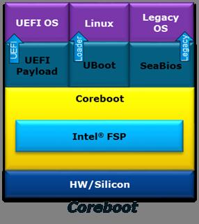
UEFI Payload
UEFI payload provides UEFI services on top of coreboot that allows UEFI OS boot.
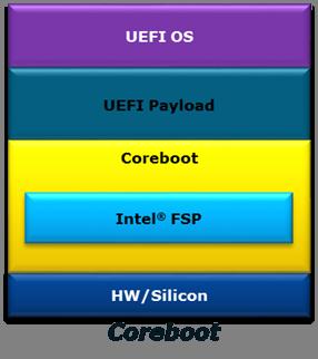
EmulatorPkg
Status
The goal of this project is to provide a common OS emulation environment, to replace Nt32Pkg and UnixPkg.
| UEFI architecture | Operating System | Status |
|---|---|---|
| IA32 | Unix | Functional |
| IA32 | Windows | Functional |
| X64 | Unix | Functional |
| X64 | Windows | Functional |
Source Repository
How to Build & Run
$ EmulatorPkg/build.sh
$ EmulatorPkg/build.sh run
The build architecture will match your host machine's architecture.
On X64 host machines, you can build + run IA32 mode as well:
$ EmulatorPkg/build.sh -a IA32
$ EmulatorPkg/build.sh -a IA32 run
Ubuntu build dependencies
To install the extra build dependencies required to build EmulatorPkg, run:
$ sudo apt-get install libx11-dev libxext-dev
Galileo
EDK II Platforms | Intel® Processor Platforms
Intel® Galileo Gen 2 Development Board
Open source UEFI firmware for the Intel® Galileo Gen 2 Development Board is available in EDK II: https://github.com/tianocore/edk2/tree/master/QuarkPlatformPkg
This 100% open source firmware project builds under MicrosoftWindows and Linux environments, and implements industry standard features such as TPM 1.2 and UEFI Secure Boot.
Intelatomprocessore3900
EDK II Platforms | Intel® Processor Platforms
UEFI Firmware Project for Intel Atom® Processor E3900 Series Processor Platforms (Leaf Hill, Up Squared & MinnowBoard
3 Module)
This project is open source UEFI firmware, based on the TianoCore EDK II codebase, for the following platforms based on the Intel Atom® Processor E3900 Series processor (formerly Apollo Lake).
- Leaf Hill Customer Reference Board (CRB)
- Up Squared by UP-BOARD (commercially available maker board, see "Supported Platforms" below)
- MinnowBoard 3 Module (Pre-production Board, ship date TBD)
Developers can download pre-built UEFI firmware images, utilities, binary object modules, and project release notes. The open source firmware project is available from the TianoCore GitHub:
https://github.com/tianocore/edk2-platforms/tree/devel-IntelAtomProcessorE3900 https://software.intel.com/en-us/articles/uefi-firmware-project-for-intel-atom-processor-e3900-series-processor-platforms
Reporting Firmware Issues
Please report any firmware issues in GitHub Issues using the following field values:
- Product: EDK2 Platforms
- Component: Minnowboard 3
See Reporting Issues for more information.
Supported Platforms
Leaf Hill CRB
Leaf Hill refers to an Intel Customer Reference Board (CRB) using the Intel Atom® Processor E3900 Series (formerly Apollo Lake).
Up Squared by UP-BOARD
Support for the UP Squared board was introduced in Release 0.71. Pre-built images and build instructions are available on Intel Developer Zone - Firmware. Please refer to the release notes for information on platform features and known issues.
NOTE: The firmware provided by this project for the UP Squared maker board is not based on the official manufacturer's firmware. This project is for experimentation and is not supported by the manufacturer (Aaeon). Flashing this firmware on the UP Squared will void the manufacturer's warranty. Thanks to Aaeon for their cooperation and providing platform porting information.
More Info:
- BIOS chip flashing on UP Squared - Information for using a SPI programmer to apply a new firmware image (factory image or custom image)
- Product Info: http://www.up-board.org/upsquared/ & http://www.up-china.net/
MinnowBoard 3 Module
MinnowBoard 3 Module is the follow-on to the MinnowBoard Max & MinnowBoard Turbot platforms. MinnowBoard platforms offer low cost & commercially available open hardware based on Intel Architecture for hardware, software and firmware developers. Hardware availability is TBD.
MinnowBoard is an open source hardware enabler, encouraging platform experimentation and derivative designs. The project supports Open Source Hardware Association principles by making designs publicly available for the community so “anyone can study, modify, distribute, make, and sell the design or hardware based on that design.”
MinnowBoard 3 Module is based on the Intel Atom® processor E3900 Series platform, utilizing the Intel® Firmware Support Package (Intel® FSP) and open source UEFI from the TianoCore EDK II project.
Note: Previous Codebase for MinnowBoard 3
Intel Atom® Processor E3900 Series Processor Platforms were originally supported by the MinnowBoard 3 codebase. At release 0.70, this codebase was updated to use UDK2018 and moved to a new branch with broader platform support.
Kaby Lake MinPlatform
EDK II Platforms | Intel® Processor Platforms
KabylakeOpenboardPkg is an EDK II for UEFI platform firmware on 7th Generation Intel® Core™ Processors and chipsets (formerly Kaby Lake platforms). This specific package supports the Intel Kaby Lake U RVP3 (reference platform), it can be used as a simple starting base to enable support for other boards.
This tree follows a "minimum platform" philosophy, providing boot to a UEFI compliant operating system using the minimum number of EDK II modules. The project uses the Intel® Firmware Support Package (Intel® FSP) for platform silicon initialization.
Minimum Platform Readme File Minimum Platform Specification
MinnowBoard 3
EDK II Platforms | Intel® Processor Platforms
Migration to devel-IntelAtomProcessorE3900
Note to developers: Release 0.70 updates the codebase to use UDK2018, and moves to a new branch of edk2-platforms on github (devel-IntelAtomProcessorE3900). Releases prior to 0.69, based on the devel-MinnowBoard3-UDK2017 & devel-MinnowBoard3 branches, are described below for historical purposes.
MinnowBoard 3 in edk2-platforms
This codebase is designed for the MinnowBoard 3 platform and Leaf Hill Customer Reference Board (CRB), using the Intel Atom® Processor E3900 Series (formerly Apollo Lake).
Project Info: Intel Developer Zone - Intel Atom® Processor E3900 Series page
Developers can download pre-built UEFI firmware images, utilities, binary object modules, and project release notes. The open source firmware project is available from the TianoCore GitHub:
https://github.com/tianocore/edk2-platforms/tree/devel-MinnowBoard3-UDK2017 https://github.com/tianocore/edk2-platforms/tree/devel-MinnowBoard3
MinnowBoard 3 Background
MinnowBoard is an open source hardware enabler, encouraging platform experimentation and derivative designs. The project supports Open Source Hardware Association principles by making designs publicly available for the community so “anyone can study, modify, distribute, make, and sell the design or hardware based on that design.”
MinnowBoard 3 was a follow-on to the MinnowBoard Max & MinnowBoard Turbot platforms. This design will be migrated to MinnowBoard 3 Module (release date TBD).
Leaf Hill CRB
Leaf Hill refers to an Intel Customer Reference Board (CRB) using the Intel Atom® Processor E3900 Series (formerly Apollo Lake).
Release 0.69 adds a separate release notes file with instructions for downloading the Leaf Hill CRB source tree and compiling an IFWI image (which slightly differs from MinnowBoard 3).
MinnowBoard UEFI Firmware
MinnowBoard is a depreciated project for 32-bit UEFI firmware development. The MinnowBoardMax and MinnowBoard 3 are more updated versions of this open hardware project.
MinnowBoard is an open hardware project based on the Intel® Atom™ processor. Technical details, schematics, and information on expansion boards (Lures). This board is no longer supported.
MinnowBoardMax
EDK II Platforms | Intel® Processor Platforms
MinnowBoard Max/Turbot

MinnowBoard Max & Turbot are low cost, commercially available, reference platforms for hardware, software and firmware developers who wish to work within an open environment. Design specifications and materials have been provided to the open community, encouraging platform experimentation and derivative designs.
The project is based on Intel® Atom™ processors. Technical details, schematics, and information on expansion boards (Lures) can be found at http://minnowboard.org
A list of currently supported boards and prices can be found at: https://minnowboard.org under the "Boards" tab
UEFI Firmware - Release
Documentation, binary images, and source build instructions are at https://software.intel.com/en-us/articles/minnowboard-maxturbot-uefi-firmware
- Binary Firmware Images ("UEFI BIOS"): 32-bit and 64-bit UEFI builds, with Debug and Release images. Includes flash update utilities and release notes.
- Binary Object Modules for which source code is not available due to the Intellectual property for both Intel silicon (microprocessor and chipset) and third party components.
- How to build Instructions for integrating the EDK II source tree (BSD license) with the Binary Object Modules to build
firmware. See the latest Release Notes .txt file at Intel Developer Zone -Minnowboard-max Firmware
Releases
- How to build with FSP
- How to configure Memory Parameters
- How to enable fTPM feature
- The open source firmware project is available from the TianoCore GitHub: https://github.com/tianocore/edk2-platforms/tree/devel-MinnowBoardMax-UDK2017
UEFI Firmware - Development
The EDK II development firmware for the MinnowBoard Max / Turbot is now available. Please see the Valleyview2 Readme for instructions to download and build a firmware image. This development firmware is ECP free and can cowork with the latest updates from EDK II.
Omap35xxPkg
Omap35xxPkg provides UEFI support For Texas Instrument OMAP35xx based platforms. This package contains drivers to support some of the OMAP35xx controllers (Flash, MMC, Gpio, etc.)
Source Repository
OVMF Boot Overview
This page provides a high-level overview of the boot process for OVMF.
SEC
- UefiCpuPkg/ResetVector/Vtf0
- Ia16/ResetVectorVtf0.asm: Starts at resetVector
- Ia16/Real16ToFlat32.asm: Mode Switch: Real => 32-bit Flat
- Ia32/SearchForBfvBase.asm: Locates the Boot FirmwareVolume (BFV)
- Ia32/SearchForSecEntry.asm: Locates the SEC Core with BFV
- Ia32/Flat32ToFlat64.asm: If 64-bit PEI, then Mode Switch: 32-bit Flat to 64-bit Long
- SEC Core: OvmfPkg/Sec
- OvmfPkg/Sec/SecMain.c: Finds PEI Core
PEI
Pre-EFI Initialization
- PEI Core: MdeModulePkg/Core/Pei
- Various PEI drivers now run
- DXE IPL (Loader for the DXE Core)
- Finds DXE Core
- If PEI is 32-bit and DXE is 64-bit, then Mode Switch: 32-bit Flat to 64-bit Long
- Jumps to DXE Core
DXE
Driver Execution Environment
- DXE Core: MdeModulePkg/Core/Dxe
- Various DXE/UEFI drivers now run
- BDS is run after all DXE architectural protocols are available
BDS
Boot Device Selection
- BDS: IntelFrameworkModulePkg/Universal/BdsDxe + IntelFrameworkModulePkg/Library/GenericBdsLib
- OvmfPkg/Library/PlatformBdsLib guides BDS in a platform specific manner
- BDS figures out what to boot, and starts devices to enable the boot
- BDS may be able to load the EFI shell if it is present in the system firmware file system
OVMF
OVMF is an EDK II based project to enable UEFI support for Virtual Machines. OVMF contains sample UEFI firmware for QEMU and KVM.
License: BSD
More information: OVMF FAQ, How to build OVMF, Boot Overview, edk2-devel
Source repository: https://github.com/tianocore/edk2/tree/master/OvmfPkg
Additional Information
- http://www.linux-kvm.org/page/OVMF
- http://wiki.xen.org/wiki/OVMF
- Gerd Hoffmann’s OVMF builds: https://www.kraxel.org/repos/
- These images are automatically built and track the latest OVMF code in the EDK II tree.
- Some of these builds include a seabios CSM and can boot non-UEFI “legacy” operating systems. (Note: seabios is GPLv3 licensed.)
- If your OS doesn’t work with RPM repositories, then you can manually download and decompress the RPM files under jenkins/edk2
Purley MinPlatform
EDK II Platforms | Intel® Processor Platforms
Project Olympus (Purley MinPlatform)
NOTE: The Purley MinPlatform code has been removed since maintenance could not be sustained. You may reference the last commit prior to removal (98c7561279) to retrieve the code.
EDK II platform firmware for the Open Compute Project (OCP) Intel XSP Motherboard. Based on the Intel Xeon Scalable Processor family (formerly codenamed "Purley").
This tree follows a "minimum platform" philosophy, providing boot to a UEFI compliant operating system using the minimum number of EDK II modules. The project uses binaries in the edk2-non-osi repository for platform silicon initialization.
Hardware Information: http://www.opencompute.org/wiki/Server/ProjectOlympus
Quark
Intel® Quark Technology
Intel® Galileo Gen 2 Development Board - http://www.intel.com/content/www/us/en/embedded/products/galileo/galileo-overview.html
QuarkPlatformPkg Readme - https://github.com/tianocore/edk2-platforms/tree/master/Platform/Intel/QuarkPlatformPkg/Readme.md
SamsungPlatformPkg
The Samsung Origen (http://www.origenboard.org/) is one of the low-cost ARM development boards. The platform is powered by a dual Cortex A9 and supports a large range of devices on boards (2x SD card, LCD & HDMI connectors, USB 2.0, etc).
Status
Tested on the revisions:
- EDK2: 13012 (14/02/2012)
- SamsungPlatformPkg: commit: ed456b2d64f3 (22/11/2011)
Build EDK2 for Samsung Origen
1. The EDK2 Samsung repository is currently located in a third-party repository. To get the sources:
svn co https://edk2.svn.sourceforge.net/svnroot/edk2/trunk/edk2 edk2 --username guest
cd $(WORKROOT)/edk2
svn co https://edk2-fatdriver2.svn.sourceforge.net/svnroot/edk2-fatdriver2/trunk/FatPkg FatPkg --username guest
git clone git://github.com/girishks/Origen-EDK-II-Package.git
mv Origen-EDK-II-Package/SamsungPlatformPkg .
2. Apply the latest patches:
patch -p1 < 0001-SamsungPlatformPkg-ExynosPkg-Do-not-initialize-the-T.patch
patch -p1 < 0002-SamsungPlatformPkg-TimerDxe-Do-not-overwrite-Timers-.patch
patch -p1 < 0003-SamsungPlatformPkg-ExynosPkg-Fixed-UART-Rx-Ready-Fla.patch
patch -p1 < 0004-SamsungPlatformPkg-OrigenBoardPkg-Update-Linux-infor.patch
patch -p1 < 0005-SamsungPlatformPkg-OrigenBoardPkg-Removed-deprecated.patch
patch -p1 < 0006-SamsungPlatformPkg-SmdkBoardPkg-Removed-memory-initi.patch
patch -p1 < 0007-SamsungPlatformPkg-SmdkBoardLib-Fixed-GCC-build-issu.patch
3. Add support for one of the supported toolchains. See ArmPkg-Toolchain
4. Build EDK2:
. edksetup.sh
make -C BaseTools
build -a ARM -p SamsungPlatformPkg/OrigenBoardPkg/OrigenBoardPkg-Exynos.dsc -t ARMLINUXGCC -b DEBUG
5. Get the Linaro Linux distribution:
- Go on the Samsung Origen Linaro webpage: http://releases.linaro.org/12.01/ubuntu/leb-origen/. Download the Origen HwPack: hwpack_linaro-leb-origen_20120123-1_armel_supported.tar.gz
- Download the minimal Linaro File System: http://releases.linaro.org/12.01/ubuntu/oneiric-images/nano/linaro-o-nano-tar-20120123-1.tar.gz
6. Install Linaro image Creator either from the tarball or the Ubuntu package.
- Getting from Linaro website:
wget http://launchpad.net/linaro-image-tools/trunk/0.4.8/+download/linaro-image-tools-0.4.8.tar.gz tar xzf linaro-image-tools-0.4.8.tar.gz cd $(WORKROOT)/linaro-image-tools-0.4.8/ sudo apt-get install parted dosfstools uboot-mkimage python-argparse python-dbus python-debian python-parted qemu-arm-static btrfs-tools command-not-found
Add linaro-media-create path to the PATH environment variable
-
Getting from the Ubuntu package:
sudo add-apt-repository ppa:linaro-maintainers/tools sudo apt-get update sudo apt-get install linaro-image-tools
7. Create the SD card. Replace the '/dev/sdX' with the device node mapped to your MMC/SC card.
sudo linaro-media-create --mmc /dev/sdX --dev origen --binary linaro-o-nano-tar-20120123-1.tar.gz --hwpack hwpack_linaro-leb-origen_20120123-1_armel_supported.tar.gz
8. Replace u-boot by the EDK2 firmware you created in step 4:
sudo dd if=Build/OrigenBoard-Exynos/DEBUG_ARMLINUXGCC/FV/ORIGENBOARD_EFI.fd of=/dev/sdb bs=512 seek=65
See this page https://wiki.linaro.org/Boards/Origen/Setup for more information about the command.
9. Insert the newly created SD card into the Origen SD card slot and power up the platform.
```text
UEFI firmware built at 19:29:37 on Feb 20 2012
Timer 2,3 Configured
UEFI firmware built at 19:29:38 on Feb 20 2012
add-symbol-file
/home/olivier/tianocore/Build/OrigenBoard-Exynos/DEBUG_ARMLINUXGCC/ARM/MdeModulePkg/Core/Dxe/DxeMain/DEBUG/DxeCore.dll
0x4FD39240
Loading DxeCore at 0x004FD39000 EntryPoint=0x004FD39241
add-symbol-file
/home/olivier/tianocore/Build/OrigenBoard-Exynos/DEBUG_ARMLINUXGCC/ARM/MdeModulePkg/Core/Dxe/DxeMain/DEBUG/DxeCore.dll
0x4FD39004
HOBLIST address in DXE = 0x4FD21590
Memory Allocation 0x00000004 0x4FF9C000 - 0x4FFEBFFF
Memory Allocation 0x00000004 0x4FF94000 - 0x4FF9BFFF
Memory Allocation 0x00000004 0x4FFEC000 - 0x4FFFFFFF
Memory Allocation 0x00000004 0x4FF84000 - 0x4FF93FFF
(...)
add-symbol-file
/home/olivier/tianocore/Build/OrigenBoard-Exynos/DEBUG_ARMLINUXGCC/ARM/MdeModulePkg/Universal/Disk/UnicodeCollation/EnglishDxe/EnglishDxe/DEBUG/EnglishDxe.dll
0x4F8B3240
Loading driver at 0x0004F8B3000 EntryPoint=0x0004F8B3261 EnglishDxe.efi
The default boot selection will start in 8 seconds
[1] SD-MMC Booting
- VenHw(B615F1F5-5088-43CD-809C-A16E52487D00)/HD(2,MBR,0x0009C1D9,0x2000,0x1A000)/uImage
- Initrd: VenHw(B615F1F5-5088-43CD-809C-A16E52487D00)/HD(2,MBR,0x0009C1D9,0x2000,0x1A000)/uInitrd
- Arguments: console=ttySAC2,115200n8 root=UUID=73ce15fe-4c31-47e5-b537-9759497e9615 rootwait ro
- LoaderType: 1
[2] EBL
[3] Boot Manager
Start:
```
Whiskey Lake MinPlatform
EDK II Platforms | Intel® Processor Platforms
WhiskeylakeOpenBoardPkg is an EDK II for UEFI platform firmware on 8th Generation Intel® Core™ Processors and chipsets (formerly Whiskey Lake platforms). This specific package supports the Intel Whiskey Lake U RVP (reference validation platform), it can be used as a simple starting base to enable support for other boards.
This tree follows a "minimum platform" philosophy, providing boot to a UEFI compliant operating system using the minimum number of EDK II modules. The project uses the Intel® Firmware Support Package (Intel® FSP) for platform silicon initialization.
Minimum Platform Readme File Minimum Platform Specification
MicroPython Test Framework for UEFI
https://github.com/tianocore/edk2-staging/tree/MicroPythonTestFramework
The MicroPython Test Framework for UEFI (MpyTestFrameworkPkg) is designed for firmware unit testing and validation.
This framework provides a set of convenient abstractions designed to remove as much boilerplate as possible from
firmware test configuration, case development, and test execution. It is general enough to be useful in a variety of
firmware testing scenarios including black box tests, white box tests, functional testing, and automating UI/human
interaction.
https://github.com/tianocore/edk2-staging/tree/MicroPythonTestFramework/MpyTestFrameworkPkg
The framework leverages MicroPython for a lightweight and minimalist implementation. A port
of the MicroPython Interpreter for UEFI is available in
edk2-staging: (MicroPythonPkg).
https://github.com/tianocore/edk2-staging/tree/MicroPythonTestFramework/MicroPythonPkg
This project was publicly announced in March 2018 and added to the edk2-staging branch in August 2018.
Code Structure
Commits are based on latest UDK2018, and include three packages:
- MicroPythonPkg: MicroPython Interpreter for UEFI
- MpyTestFrameworkPkg: MicroPython Test Framework for UEFI
- MpyTestCasePkg: One placeholder to contain the future platform test cases repo.
See README.md files in Package folders for more information.
The following git commands sync with the latest branch:
git clone https://github.com/tianocore/edk2-staging
cd edk2-staging
git checkout MicroPythonTestFramework
git submodule update --init –recursive
Note: The last command will sync all submodule sources
References
MicroPython Project Website: https://micropython.org/
Implementing MicroPython as a UEFI Test Framework
Python Tools
The following tools are required for building EDK II BaseTools and instructions are provided in the BuildTool Setup Guide.
Resources
Version Info
All of the Python tools located in the BaseTools sub-project are built and tested using:
| Tool | Current Version | Future Version |
|---|---|---|
| Python | 2.7.3 | 2.7.7 |
| wxPython (GUI tools only) | 2.8.1 Unicode | |
| cxFreeze (Windows and Linux) | 4.2.3 | Pending |
| py2app (Mac OS/X) | 0.3.5 | |
| antlr3 | antlr_python_runtime-3.1.3-py2.7 |
UEFI Driver Wizard
v0.11 (03-05-2012, Windows MSI) | ReadMe | Wizard-Getting-Started
The UEFI Driver Wizard (also compatible with Linux/Unix/Mac Download from this github link) is an open source program designed to accelerate the development of new UEFI drivers using a GUI-based template generator. This wizard provides basic support for the most common categories of UEFI drivers.
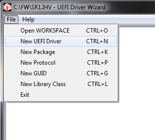
The UDK2014.IHV Setup Guide (Driver Developer Release) is a subset of the UEFI Development Kit (UDK2014) designed for use with the UEFI Driver Wizard. This release only contains the packages essential for independent hardware vendor (IHV) driver development.
Please refer to the UEFI Driver Wizard ReadMe. Check out the Wizard-Getting-Started for more information.
Wizard Getting Started
Installation Overview
Note: examples are based on Microsoft Windows 7 with Visual Studio 2008. Please review the release notes for installation on other OS/compiler environments
- Make sure you have a compiler installed that supports UDK2014
- Download the UDK2014 Driver Developer Release
- Unzip UDK2014.IHV.zip into a workspace directory (example: C:\FW\UDK2014.IHV)
- Download and install the UEFI Driver Wizard .msi
- Open the UEFI Driver Wizard, select 'File -> Open Workspace' and select the UDK2014.IHV workspace directory
After these steps are complete, the UEFI Driver Wizard is ready to use for the first time.
Configure the Workspace
The UEFI Driver Wizard requires a subset of UDK2014 or EDK II setup before running the wizard. The UDK2014.IHV.zip Driver Developer Release contains the minimal set of components needed to create UEFI drivers. Please refer to the UDK2014.IHV-Setup-Guide for more information.
After starting the UEFI Driver Wizard, use the 'File -> Open Workspace' option to select the workspace directory (example: C:\FW\SR1.IHV).
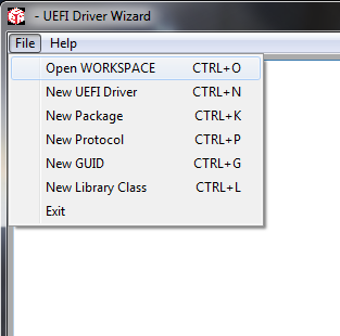
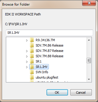
Note that edksetup.bat or edksetup.sh must be run in the workspace directory prior to using the UEFI Driver Wizard. The EDK II configuration files in the Conf directory are used by the UEFI Driver Wizard to detect a valid workspace. If edksetup has not been run in the workspace directory the UEFI Driver Wizard will return an error.
Create a Blank Driver
Once the workspace directory has been configured, use the 'New UEFI Driver' dialog to create a blank driver in the workspace directory.
Note that the wizard may return an error at the end of the process if required fields are left blank (example: UEFI Driver Name). For details on this dialog, please refer to the New UEFI Driver Dialog page.
EDK
This is the older development environment; Pre-EDK II. See the Differences between EDK and EDK II
- EFI Shell the open-source component of Intel's implementation of the EFI Specification
- edk-fat-driver a project for the FAT32 File System Driver
- network-io SNP NT32 Network I/O
- edk-apps EDK applications
- EDK Network UNDI Driver - Download The latest Intel(R) PRO/1000 Network UEFI/ EDK Driver
- EDK Client Patch 9 - Download Latest EDK Client Patch 9 -20130117 Ref 518096
EFI Shell Project
This is the older EFI shell; Pre-ShellPkg
- EDK EFI Shell - Matched to EDK Releases
Other Projects
- PI SCT Platform Initializiation Self-certification test projtect (Separate SF Project pi-sct)
- framework-sct EFI device driver loader, application launcher, OS booter
- edkcontrib Contributions to EDK for expanded functionality
- efi-sct UEFI SCT has been moved to the UEFI Forum at http://www.uefi.org members page.
Older, unmaintained projects
- EFI Toolkit is a set of tools that support rapid porting and development of EFI applications, and promote a uniform pre-boot environment on 32 and 64 bit based platforms.
Capsule Based System Firmware Update Implementation
Back to Capsule Based System Firmware Update
Supporting SignedCapsulePkg in an EDK II project
requires several platform-specific items.
PlatformFlashAccessLib Library Instance
In order for a signed capsule to update the non-volatile storage device that that contains the system firmware contents
that may be updated, an instance of the PlatformFlashAccessLib must be implemented. This library class provides a
single API to update a portion of the non-volatile storage device.
EFI_STATUS
EFIAPI
PerformFlashWrite (
IN PLATFORM_FIRMWARE_TYPE FirmwareType,
IN EFI_PHYSICAL_ADDRESS FlashAddress,
IN FLASH_ADDRESS_TYPE FlashAddressType,
IN VOID *Buffer,
IN UINTN Length
);
A template of the PlatformFlashAccessLib is provided in SignedCapsulePkg
(SignedCapsulePkg/Library/PlatformFlashAccessLibNull).
Complete examples of this library can be found in the Intel Galileo Gen 2 & MinnowBoard Max EDK II projects:
QuarkPlatformPkg/Feature/Capsule/Library/PlatformFlashAccessLib
Vlv2TbltDevicePkg/Feature/Capsule/Library/PlatformFlashAccessLib
It is recommended that this new platform specific library instance be placed in your platform package.
<Your Platform Package>/Feature/Capsule/Library/PlatformFlashAccessLib
System Firmware Descriptor PEIM
A PEIM is used to provide a System Firmware Descriptor that provides the current system firmware version information.
This information is stored in a RAW section of the PEIM FFS file. The PEIM is responsible for reading the RAW section
and setting the VOID* PCD called gEfiSignedCapsulePkgTokenSpaceGuid.PcdEdkiiSystemFirmwareImageDescriptor to the
contents of the RAW section. The Firmware Management Protocol for the system firmware uses this PCD to determine the
current version of the system firmware.
Complete examples of this PEIM can be found in the Intel Galileo Gen 2 EDK II project:
QuarkPlatformPkg/Feature/Capsule/SystemFirmwareDescriptor
It is recommended that the System Firmware Descriptor PEIM implementation be placed under your platform package directory.
<Your Platform Package>/Feature/Capsule/SystemFirmwareDescriptor
The System Firmware Descriptor information is implemented in the file SystemFirmwareDescriptor.aslc.
The version and string information must be updated for the system firmware update requirements.
The IMAGE_TYPE_ID_GUID define must be set to a new GUID value(using C structure syntax) for the
platform. This GUID value must be one of the GUID values the platform supports for Capsule Base
System Firmware Updates. The PCD called gEfiMdeModulePkgTokenSpaceGuid.PcdSystemFmpCapsuleImageTypeIdGuid
is set to an array of one or more of IMAGE_TYPE_ID_GUID values (using byte array syntax) in the
Platform DSC file described in the
Platform DSC PCDs section.
The following #defines from SystemFirmwareDescriptor.aslc need to be updated for your platform:
#define PACKAGE_VERSION 0xFFFFFFFF
#define PACKAGE_VERSION_STRING L"<Package Version String>"
#define CURRENT_FIRMWARE_VERSION 0x00000002
#define CURRENT_FIRMWARE_VERSION_STRING L"<Current firmware version string>"
#define LOWEST_SUPPORTED_FIRMWARE_VERSION 0x00000001
#define IMAGE_ID SIGNATURE_64('_', '_', '_', '_', '_', '_', '_', '_')
#define IMAGE_ID_STRING L"<Image ID string>"
#define IMAGE_TYPE_ID_GUID {0xe698490d, 0xc1fa, 0x47fd, { 0x86, 0x3, 0x69, 0xcd, 0x67, 0x8c, 0x5c, 0x39} }
System Firmware Update Configuration INI File
This a System Firmware Update Configuration INI file provides the inventory of components in a capsule that are used by
the system firmware's Firmware Management Protocol to update one or more components in the system firmware's
non-volatile storage device using the PlatformFlashAccessLib instance implemented in the step above.
The INI file is ASCII text. The first section is [Head]. The value of NumHeadUpdate must be set to the number of
components in the inventory. There must be an UpdateX statement assigned to a unique name for each component in the
inventory. The example below shows a [Head] section that describes a single component.
[Head]
NumOfUpdate = 1
Update0 = MyPlatformFvMain
For each UpdateX statement, there must be section with the assigned name. In this example
the unique component name is MyPlatformFvMain. The component section provides the type
of firmware, address type, FFS file GUID from the capsule image to use, the address range of
FFS file to read, and the address range of the system's non-volatile storage device to update
using PlatformFlashAccessLib implemented above. The example below shows the
[MyPlatformFvMain] section from the [Head] example above.
[MyPlatformFvMain]
FirmwareType = 0 # SystemFirmware
AddressType = 0 # 0 - relative address, 1 - absolute address.
BaseAddress = 0x00500000 # Base address offset on flash
Length = 0x001E0000 # Length
ImageOffset = 0x00500000 # Image offset of this SystemFirmware image
FileGuid = 26961C31-66DC-48A5-891C-25438BDE1430 # PcdEdkiiSystemFirmwareFileGuid
FirmwareType:0- SystemFirmware,1- NvRam.AddressType:0- relative address,1- absolute address.BaseAddress: Base address offset of non-volatile storage device in hexidecimal (e.g.0x00400000)Length: Image Length in hexidecimal (e.g.0x00001000)ImageOffset: Image offset of data in FileGuid FFS file in hexidecimal (e.g.0x00400000)FileGuid: Register format GUID of FFS File GUID in FmpPayload (e.g.26961C31-66DC-48A5-891C-25438BDE1430)
NOTE: A [Name?] section may have different FileGuid. Only the ones whose FileGuid matches
PcdEdkiiSystemFirmwareFileGuid are used. Non-matching ones are ignored.
Complete examples of System Firmware Update Configuration INI Files can be found the paths listed below. These examples build capsules that may be used for both system firmware update and system firmware recovery.
QuarkPlatformPkg/Feature/Capsule/SystemFirmwareUpdateConfig/SystemFirmwareUpdateConfig.iniVlv2TbltDevicePkg/Feature/Capsule/SystemFirmwareUpdateConfig/SystemFirmwareUpdateConfig.iniVlv2TbltDevicePkg/Feature/Capsule/SystemFirmwareUpdateConfig/SystemFirmwareUpdateConfigGcc.ini
It is recommended that the System Firmware Update Configuration INI file implementation be placed
in a platform package in the path <Your Platform Package>/Feature/Capsule/SystemFirmwareUpdateConfig.
Back to Capsule Based System Firmware Update
Capsule Based System Firmware Update Verify Generated Keys
Back to Capsule Based System Firmware Update
The following steps can be used to verify that the capsule-based system firmware update feature has been integrated into a platform correctly. These steps use generated keys for a specific platform. One key generation method is described in Capsule Based System Firmware Update Generate Keys.
The steps provided in this section are focused on verifying the use of generated keys. A
more complete set of verification steps for the test signing key are provided in
Capsule Based System Firmware Update Verify Test Keys.
These steps use the CapsuleApp.efi utility to display and verify fields in the FMP, ESRT,
and Capsule structures.
Each step in this sequence depends on all the previous steps. If any step in this sequence does not match expectations, then debug and resolve the integration issue before proceeding to the next step.
Add Generated Private Keys to tools_def.txt
- Update
Conf/tools_def.txtto use generated private keys. The bottom of tools_def.txt has a section labeled Pkcs7Sign tool definitions. The default settings for this section does not include a*_*_*_PKCS7SIGN_FLAGSstatement. This means the test signing keys are used by default. In order for the build to sign system firmware update capsules using generated private keys, the--signer-private-cert,--other-public-cert, and--trusted-public-certflags must be provided. The example below adds these three flags and uses the environment variables calledKEYS_PATHandKEYS_BASE_NAMEto specify the path and base name of generated private keys. This follows the key file naming used in Capsule Based System Firmware Update Generate Keys.
##################
## Pkcs7Sign tool definitions
##################
*_*_*_PKCS7SIGN_PATH = Pkcs7Sign
*_*_*_PKCS7SIGN_GUID = 4AAFD29D-68DF-49EE-8AA9-347D375665A7
*_*_*_PKCS7SIGN_FLAGS = --signer-private-cert ENV(KEYS_PATH)\ENV(KEYS_BASE_NAME)Cert.pem --other-public-cert ENV(KEYS_PATH)\ENV(KEYS_BASE_NAME)Sub.pub.pem --trusted-public-cert ENV(KEYS_PATH)\ENV(KEYS_BASE_NAME)Root.pub.pem
This is one of many possible methods to sign images. This example is a simple method that helps verify that the test keys can be replaced with generated keys. Each product owner must decide on the signing method and signing tools that provide proper protection of their private keys.
Add Generated Public Key to Platform DSC
- Update Platform DSC file to set the PCD
gEfiSecurityPkgTokenSpaceGuid.PcdPkcs7CertBufferto the generated public key. The example below adds the generated public key to the[PcdsDynamicExVpd]section.<MaxSize>must be set to a value that is at least as big as the number of bytes in the generated<public key>.<public key>is the list of bytes from the binary.cerfile that is described in Capsule Based System Firmware Update Generate Keys. A hex dump utility may be used to convert the binary file to the list of hex values. The example below shows the PCD setting for the test signing public key from the fileBaseTools\Source\Python\Pkcs7Sign\TestRoot.cer
[PcdsDynamicExVpd]
!if $(CAPSULE_ENABLE)
#
# Custom public signing key PCD statement
#
# gEfiSecurityPkgTokenSpaceGuid.PcdPkcs7CertBuffer|*|<MaxSize>|{<public key>}
#
gEfiSecurityPkgTokenSpaceGuid.PcdPkcs7CertBuffer|*|756|{0x30, 0x82, 0x02, 0xf0, 0x30, 0x82, 0x01, 0xdc, 0xa0, 0x03, 0x02, 0x01, 0x02, 0x02, 0x10, 0x34, 0x30, 0x27, 0x7f, 0x05, 0x3d, 0x95, 0x85, 0x43, 0xa0, 0xa4, 0xf5, 0x0c, 0x9a, 0xe7, 0xca, 0x30, 0x09, 0x06, 0x05, 0x2b, 0x0e, 0x03, 0x02, 0x1d, 0x05, 0x00, 0x30, 0x13, 0x31, 0x11, 0x30, 0x0f, 0x06, 0x03, 0x55, 0x04, 0x03, 0x13, 0x08, 0x54, 0x65, 0x73, 0x74, 0x52, 0x6f, 0x6f, 0x74, 0x30, 0x1e, 0x17, 0x0d, 0x31, 0x36, 0x30, 0x38, 0x30, 0x34, 0x31, 0x35, 0x30, 0x31, 0x34, 0x38, 0x5a, 0x17, 0x0d, 0x33, 0x39, 0x31, 0x32, 0x33, 0x31, 0x32, 0x33, 0x35, 0x39, 0x35, 0x39, 0x5a, 0x30, 0x13, 0x31, 0x11, 0x30, 0x0f, 0x06, 0x03, 0x55, 0x04, 0x03, 0x13, 0x08, 0x54, 0x65, 0x73, 0x74, 0x52, 0x6f, 0x6f, 0x74, 0x30, 0x82, 0x01, 0x22, 0x30, 0x0d, 0x06, 0x09, 0x2a, 0x86, 0x48, 0x86, 0xf7, 0x0d, 0x01, 0x01, 0x01, 0x05, 0x00, 0x03, 0x82, 0x01, 0x0f, 0x00, 0x30, 0x82, 0x01, 0x0a, 0x02, 0x82, 0x01, 0x01, 0x00, 0x94, 0xe6, 0x33, 0x4f, 0x56, 0xc3, 0x07, 0xa0, 0xd0, 0x99, 0x57, 0xc3, 0xe1, 0x56, 0x42, 0x01, 0x70, 0x59, 0x1c, 0x2f, 0x4a, 0x66, 0x8f, 0x34, 0x9e, 0x93, 0xbd, 0xb6, 0xec, 0x92, 0xa4, 0x90, 0x51, 0x5d, 0xc6, 0x8f, 0xb5, 0xc3, 0x86, 0x15, 0xdf, 0x60, 0x80, 0xbe, 0xb8, 0x78, 0x59, 0x5b, 0x9b, 0xfd, 0x27, 0x92, 0x69, 0xcc, 0xca, 0x8e, 0x3e, 0x9e, 0x81, 0x47, 0x5b, 0x84, 0xef, 0x5c, 0x9b, 0xb3, 0x4a, 0x43, 0x5b, 0x8d, 0x0b, 0x31, 0x04, 0x00, 0xb6, 0x8a, 0xc0, 0xa9, 0xf5, 0x21, 0xd0, 0x3f, 0xcd, 0xb0, 0x67, 0x7d, 0x50, 0x33, 0x2e, 0xfb, 0x1b, 0x2c, 0x16, 0x2e, 0xee, 0x56, 0x01, 0x87, 0xf6, 0xc8, 0xd4, 0x53, 0x07, 0x67, 0x99, 0x0b, 0x46, 0xbf, 0x1d, 0x90, 0xc6, 0xdb, 0x7f, 0x6d, 0x62, 0x0c, 0x4a, 0xac, 0xa8, 0xa2, 0x3c, 0x79, 0x0f, 0xad, 0x8f, 0xfe, 0xc1, 0xe8, 0xe5, 0x27, 0x3d, 0xf9, 0xa6, 0x9a, 0x1d, 0xec, 0x9a, 0x5f, 0x62, 0x51, 0x2e, 0x98, 0x1d, 0x29, 0xba, 0x6b, 0x8a, 0xfb, 0x43, 0x0e, 0x68, 0x29, 0xf5, 0xbe, 0x67, 0x48, 0x44, 0x28, 0x45, 0xfe, 0x1d, 0x3b, 0x50, 0x72, 0x6a, 0xc0, 0xbb, 0x0c, 0x9f, 0x02, 0x61, 0xad, 0x63, 0xa7, 0x87, 0xf6, 0x32, 0x9f, 0x3e, 0x16, 0x5c, 0xee, 0xcc, 0x05, 0xbd, 0x17, 0xe8, 0x46, 0x52, 0xaf, 0x50, 0x8a, 0xa6, 0x7e, 0x16, 0x69, 0x83, 0x69, 0x5b, 0x6e, 0x4d, 0xc7, 0xcf, 0x80, 0xb8, 0xcd, 0xf6, 0x66, 0x3f, 0xbe, 0x6c, 0xa0, 0xe8, 0x9c, 0x26, 0x60, 0xba, 0xa9, 0x05, 0xdd, 0x71, 0x4a, 0xbd, 0x00, 0xa8, 0x0c, 0xf7, 0x50, 0xab, 0x44, 0xd6, 0x3e, 0x87, 0x21, 0x3c, 0x2d, 0xe6, 0x33, 0x27, 0x5e, 0x21, 0x27, 0xb9, 0xdc, 0x38, 0x48, 0xd6, 0x3a, 0x96, 0xe1, 0x17, 0x47, 0x65, 0x65, 0xce, 0x3d, 0x02, 0x03, 0x01, 0x00, 0x01, 0xa3, 0x48, 0x30, 0x46, 0x30, 0x44, 0x06, 0x03, 0x55, 0x1d, 0x01, 0x04, 0x3d, 0x30, 0x3b, 0x80, 0x10, 0xce, 0xb5, 0x7a, 0xcf, 0xe5, 0x21, 0xc7, 0x6b, 0xf3, 0xec, 0x92, 0xd4, 0xbf, 0x65, 0x2a, 0x35, 0xa1, 0x15, 0x30, 0x13, 0x31, 0x11, 0x30, 0x0f, 0x06, 0x03, 0x55, 0x04, 0x03, 0x13, 0x08, 0x54, 0x65, 0x73, 0x74, 0x52, 0x6f, 0x6f, 0x74, 0x82, 0x10, 0x34, 0x30, 0x27, 0x7f, 0x05, 0x3d, 0x95, 0x85, 0x43, 0xa0, 0xa4, 0xf5, 0x0c, 0x9a, 0xe7, 0xca, 0x30, 0x09, 0x06, 0x05, 0x2b, 0x0e, 0x03, 0x02, 0x1d, 0x05, 0x00, 0x03, 0x82, 0x01, 0x01, 0x00, 0x6b, 0x0d, 0xe0, 0x0a, 0xd0, 0xee, 0x5b, 0x3f, 0xb6, 0x73, 0x48, 0x62, 0xe8, 0xf4, 0x5b, 0xe1, 0xed, 0xd9, 0x00, 0xc5, 0xe5, 0x0e, 0x68, 0xfb, 0x53, 0x33, 0x30, 0x6a, 0x60, 0xba, 0xee, 0x38, 0x5b, 0x51, 0x63, 0x70, 0xd5, 0x7e, 0x05, 0xfe, 0xe4, 0x45, 0x2a, 0x15, 0x62, 0x1b, 0xfc, 0xd8, 0x75, 0x93, 0x56, 0xf6, 0xe6, 0x06, 0x85, 0x21, 0xf7, 0x08, 0x47, 0x26, 0xb9, 0xfe, 0x05, 0x4e, 0x90, 0x22, 0x54, 0xf4, 0x39, 0x09, 0x4c, 0x5c, 0x8e, 0xcd, 0x7c, 0x3b, 0xaf, 0x4b, 0x2d, 0x18, 0x06, 0xf4, 0x5c, 0x24, 0x2a, 0x64, 0xf7, 0x59, 0x75, 0x28, 0x97, 0xa9, 0x90, 0x2c, 0xba, 0x46, 0x02, 0x6a, 0x64, 0x66, 0x49, 0x32, 0xcb, 0x5d, 0x34, 0xfe, 0x24, 0xe4, 0x44, 0xb0, 0xc2, 0xad, 0x17, 0x1b, 0x05, 0x7d, 0xd3, 0x58, 0x88, 0x2e, 0xbe, 0x0e, 0xd7, 0x2b, 0xca, 0x5c, 0xbf, 0x28, 0x25, 0x3d, 0xd8, 0xbb, 0x3c, 0x38, 0x52, 0xe6, 0x27, 0xfa, 0xd2, 0xb8, 0x45, 0x6b, 0x5f, 0x7f, 0x4b, 0xb0, 0x23, 0x05, 0xe8, 0xaf, 0x67, 0xe8, 0xe2, 0x6c, 0x2f, 0x9f, 0xf8, 0x73, 0x7f, 0xc3, 0x17, 0xbc, 0xb2, 0x6a, 0x5b, 0x2a, 0xf3, 0x6b, 0xd3, 0xdc, 0x7f, 0xdf, 0x2f, 0xd0, 0xab, 0x06, 0x0c, 0xfe, 0x03, 0xe7, 0x8d, 0x82, 0xec, 0x84, 0x3d, 0xc8, 0x7d, 0xed, 0xcb, 0x6a, 0x5b, 0x35, 0x48, 0x55, 0x07, 0xfb, 0xaa, 0x78, 0x1a, 0x01, 0xbb, 0x98, 0x45, 0x8b, 0xda, 0x8a, 0xe3, 0x21, 0x57, 0x86, 0x15, 0x23, 0x17, 0x50, 0x1b, 0x9c, 0xbc, 0x1a, 0x59, 0xa8, 0x2a, 0xad, 0x3a, 0x7e, 0x01, 0x24, 0x83, 0xf7, 0xb0, 0x61, 0xe6, 0xbd, 0x4f, 0xd9, 0x91, 0x90, 0xa7, 0x2a, 0xb9, 0x0c, 0x3b, 0xab, 0x95, 0x20, 0x1c, 0xf0, 0x74, 0xce, 0x02, 0xba, 0x14, 0x5d, 0xf1, 0x91, 0x25, 0x4a}
!endif
- A helper tool in
BaseTools/Scripts/BinToPcd.pyis availble to simplify setting large PCDs such asgEfiSecurityPkgTokenSpaceGuid.PcdPkcs7CertBuffer. This helper tool can be used to convert a binary file to the list of hex values.
BinToPcd.py -i BaseTools\Source\Python\Pkcs7Sign\TestRoot.cer
BinToPcd.py also supports the generation of an entire PCD statement. The following example
generates a PCD statement for a VPD section and sets the size of the PCD to the size of the
test signing public key input file BaseTools\Source\Python\Pkcs7Sign\TestRoot.cer
BinToPcd.py -p gEfiSecurityPkgTokenSpaceGuid.PcdPkcs7CertBuffer -t VPD -i BaseTools\Source\Python\Pkcs7Sign\TestRoot.cer
BinToPcd.py also supports the generation of an output file that can be included from a
platform DSC file using a !include statement. This allows a pubic key value to be updated
without updating to the platform DSC file. Instead, the BinToPcd.py helper tool is run with
a new public key input file. The example below shows the generation of the output file
MyPublicKey.inc.
BinToPcd.py -p gEfiSecurityPkgTokenSpaceGuid.PcdPkcs7CertBuffer -t VPD -i BaseTools\Source\Python\Pkcs7Sign\TestRoot.cer -o MyPublicKey.inc
The following is the update to a platform DSC file to include the PCD statement generated by
the BinToPcd.py helper tool above. This example assumes MyPublicKey.inc is in the same
directory as the platform DSC file.
[PcdsDynamicExVpd]
!if $(CAPSULE_ENABLE)
#
# Custom public signing key from include file
#
# gEfiSecurityPkgTokenSpaceGuid.PcdPkcs7CertBuffer|*|<MaxSize>|{<public key>}
#
!include MyPublicKey.inc
!endif
Build and Boot Firmware Image
- If the
tools_def.txtconfiguration sown above is used, then set theKEYS_PATHandKEYS_BASE_NAMEenvironment variables to the path and base name of generated private keys. The following example sets the environment variables for generated keys in aKeysdirectory in thewQuarkPlaytformPkgand a base name for the key set toGalileoGen2.
set KEYS_PATH=%WORKSPACE%\edk2\QuarkPlatformPkg\Keys
set KEYS_BASE_NAME=GalileoGen2
These environment variable settings use the following generated private key files
QuarkPlatformPkg/Keys/GalileoGen2Root.pub.pem
QuarkPlatformPkg/Keys/GalileoGen2Sub.pub.pem
QuarkPlatformPkg/Keys/GelileiGen2Cert.pem
- Build firmware image setting the
-D CAPSULE_ENABLEflag.
build -a IA32 -t VS2015x86 -p QuarkPlatformPkg/Quark.dsc -D CAPSULE_ENABLE
-
Update target with new firmware image
-
Boot target to Boot Manager. The front page should not show a
WARNING: Test key detected.message. If logging is enabled, then this same message should not be present in the log. If this message is still displayed, then the firmware is still using the public test signing key.
Build System Firmware Update Capsule
-
Update System Firmware Descriptor PEIM .aslc file to a higher version by updating the
CURRENT_FIRMWARE_VERSIONandCURRENT_FIRMWARE_VERSION_STRINGdefines. This file is described in Capsule Based System Firmware Update Implementation -
Build firmware image again setting the
-D CAPSULE_ENABLEflag
build -a IA32 -t VS2015x86 -p QuarkPlatformPkg/Quark.dsc -D CAPSULE_ENABLE
Verify System Firmware Update Capsule
-
Copy System Firmware Update Capsule Image with higher version to a USB drive
-
Run
CapsuleApp.efi <CapsuleImage>to load and process the system firmware update capsule. -
If logging is enabled, then view the boot log to verify capsule processing.
-
Run
CapsuleApp.efi -Pto view the Firmware Management Protocol details and verify that the version information matches the version of the capsule that was processed.
Back to Capsule Based System Firmware Update
Documents
Documents including Specification, User Manuals, White Papers, and other member contributions are listed here.
EDK
II Documents
EDK Documents
EFI Compatibility Package (ECP)
What is ECP?
The EFI Compatibility Package (ECP) bridges EDK I code into EDK II projects. It is considered deprecated on modern platforms, and we do not recommend continuing to use ECP in current projects.
ECP FAQ
Why does ECP start at EDK 1.01 when it only supports UEFI 2.0?
The purpose of the ECP is to provide backwards compatibility for EDK I style source modules that assume UEFI 2.0/Framework 0.9. The ECP uses a number of techniques that allow these EDK I source modules to execute correctly when run on top of the UDK 2010 UEFI 2.3/PI 1.2 core. This preserves customers existing investments in EDK I modules by allowing them to be used “as is” in UDK 2010 based firmware. This also allows customers to plan when/if their exiting modules will be ported to UDK 2010 without the use of ECP.
Is there any Documentation on porting EDK to EDK II without ECP?
There is a plan to have a tool MPT module porting tool in Q1 2011 with documentation. This would convert an 1117 driver to pure EDK II driver. This plan has still in progress as of Q1 2012.
What are the constraints when using ECP?
If a platform is ported from EDK to EDK II the One exception is the SEC phase.
Where can I find further information about ECP?
There is currently not any Documented ECP guide but the help (.chm and .html) files for the package are on tianocore.org: Latest release will be on UDK2010 under the Documents Section of the latest release for the EdkCompatibilityPkg
What are Native and ECP? And what is different about the EDK II libraries?
- ) Native means we do not use the ECP EDK compatibility package. There are no EDK style drivers / modules.
- ) EDK II libraries are a richer set of libraries. Instances can be mapped to same library name. EDK II defines a lib class in the .h file which defines the APIs of the library and there can be many instances or implementations that have that same library class name. For example, a different implementation for a lib can be in PEI while another implementation is in DXE. The goal is to have a consistent set of libraries that the code commonly uses and allow to have different implantations of the libraries for the different phases to easily migrate and port source code. This should help in the porting effort for example writing a PEIM and moving it to the DXE phase.
With EDK II and ECP does that mean the ECP has its own library?
Yes, ECP has set of libraries that are understood by EDK I to build in EDK II. If however, there are libraries developed beyond EDK I they will need to be ported to EDK II.
With regard to HII protocols what is the level to use with the ECP?
To use ECP the code and VFR code must be UEFI 2.0/Framework 0.9. This means using the HII from Framework 0.9.
EDK II Information
EDK II Libraries and Helper files
- UDK2018: See the documentation on the UDK2018 page. Help documents in CHM and Zip formats for the UDK2018 release, including all libraries and documentation for UDK2018.
- UDK2017: See the documentation on the UDK2017 page. Help documents in CHM and Zip formats for the UDK2017 release, including all libraries and documentation for UDK2017.
- UDK2015: See documents on the UDK2015 page. Help documents in CHM and Zip formats for the UDK2015 release, including all libraries and documentation for UDK2015.
EDK II Overview
EDK II was the response to the EFI community’s request for a better build and version tracking environment for UEFI and PI development. The main difference between the EDK II to the original EDK is the Enhanced Build Environment of the EDK II.
The advantages of the Enhanced Build Environment include:
- Operating System independence
- Flexibility in choosing the compiler and assembler tools
- The ability to generate working code using open source build tools and applications
- Enhanced development and build capability of modules and module packages
- Use of build configuration tools and data sets to provide flexible process
- Online source control allows users to contribute code and become participants
The EDK II enhanced build environment is a significant departure from the build environment of the original EDK. There are many new concepts and features in the EDK II, which have altered the environment. If you are familiar with the original EDK these changes will be obvious, while the benefits of them will be apparent to everyone. The new structure, along with package owners is documented in the EDKII Packages.
It is important to note, that the compiled results of the EDK II are equivalent to the original EDK, the changes are in the build environment and only affect the sources at that level. Any differences in the code files are only to support the changes in the build environment, once the modules are created, they are functionally identical.
The EDK II is classified at a development level project and the EDK is an official level project. The EDK is still intended to be used for volume production and shipments while the EDK II is being further refined through additional development.
As the EDK II project matures and the active participation of the EFI open source community members expand the project’s scope (features, functionality, and support) the EDK II project will grow into an official level project. In the mean time, we are pleased in your interest in the EDK II project and encourage your participation and feedback.
EDK II User Documentation
|
EDK II User Documentation |
|||
|---|---|---|---|
|
Document Download |
Description |
||
|
UEFI Packaging Tool (UEFIPT) Quick Start 1.2 This document provides a definitive list of steps to follow which will result in the creation of a UEFI Distribution Package using the UEFI Packaging Tool (UEFIPT) within a Microsoft Windows* OS and Linux OS environments.
|
|||
|
Signing UEFI Images.pdf V1.31 Version 1.31. This document describes how to sign UEFI images for the development and test of UEFI Secure Boot using the UDK2010.SR1 release.
Updates and clarifications related to UEFI Spec conformance regarding KEK and DB usages See also SecurityPkg for more information on How to enable security, TPM, User identification (UID), secure boot and authenticated variable. NOTE SVNs: For Nt32Pkg requires -r13186, For OVMF Requires -r13160 beyond UDK2010.SR1 release version
|
|||
|
The UEFI Driver Writer's Guide is designed to aid in the development of UEFI Drivers using the EDK II open source project as a development environment. Please refer to the Driver Developer page for more information. |
|||
|
EDKII User Manual V 0.7 This document provides detailed instructions for downloading, configuring, and building an EDK II project as well as running EDKII Emulation Environments.
|
|||
|
EDK II Module Writer's Guide v 0.7 The document is a guideline for new EDK II module developers, and provides detailed instructions on how to develop and build a new module, and how to release with a package.
|
|||
|
Performance Optimization Technical documentation for Performance Optimization for EDK II
|
|||
|
UEFI SCT Case Writers Guide .91 This document defines the guidelines for writing the test cases under UEFI Self-Certification Test (SCT) and introduces the UEFI SCT source tree. This document is intended for anyone interested in developing or porting tests for the UEFI SCT
|
|||
EDK II White Papers
This page contains a list of White papers and technical documents in chronological order Check EDK II Security White Papers for documents on security
|
EDK II White papers |
|||
|---|---|---|---|
|
Download PDF |
Title Description *Date Published |
||
|
A Tour Beyond BIOS Open Source IA Firmware Platform Design Guide in EDK II - V2- contributed by Vincent Zimmer, Jiewen Yao, Michael Kubacki, Amy Chan, Rangasai Chaganty and Chasel Chiu This paper introduces a design guide for an EDK II open source IA firmware solution. In order to make an open IA firmware solution simple, we demonstrate a firmware design approach with minimal features. The only criteria are
We can remove many unnecessary silicon or platform features like Capsule update, Recovery, S3 resume, SMBIOS, EC, Super IO (SIO), I2C, and only enable ACPI & SMM to support booting. |
|||
|
A Tour Beyond BIOS- Security Enhancement to Mitigate Buffer Overflow in UEFI contributed by Jiewen Yao, Vincent Zimmer and Jian Wang A buffer overflow is “one of the most important exploitation techniques in the history of computer security.” [ Tanenbaum ] “Buffer overflows are ideally suited for introducing three of the most important protection mechanisms available in most modern systems: stack canaries, data execution protection, and address-space layout randomization.”[ Tanenbaum ] However, the current UEFI firmware implementation only adopted a few of these mechanisms. This paper will introduce how to enable the protection mechanisms in UEFI firmware to harden the pre-boot phase.
|
|||
|
EDK II HTTP Boot Getting Started Guide- contributed by Ye Ting, Fu Siyuan, and Zhang Lubo This document is a getting started guide for using the HTTP boot capability introduced in the UEFI Specification, revision 2.5.
|
|||
|
Getting Started with UEFI HTTPS Boot on EDK II contributed by Wu Jiaxin, Fu Siyuan and Brian Richardson HTTP over TLS (HTTPS) boot is a standard implementation for securely booting using the Unified Extensible Firmware Interface (UEFI) over a network device. HTTPS Boot is especially important for clients using potentially insecure networks outside of corporate infrastructure. Security for UEFI HTTPS Boot is provided by the underlying Transport Layer Security (TLS). This paper assumes the reader is familiar with the EDK II HTTP Boot Getting Started Guide
|
|||
|
A Tour Beyond BIOS- Memory Protection in UEFI BIOS contributed by Jiewen Yao and Vincent Zimmer Data execution protection (DEP) is intended to prevent an application or service from executing code from a non-executable memory region. This helps prevent certain exploits that store code via a buffer overflow. In the White paper [ https://github.com/tianocore-docs/Docs/raw/main/White_Papers/A_Tour_Beyond_BIOS_Securiy_Enhancement_to_Mitigate_Buffer_Overflow_in_UEFI.pdf A Tour Beyond BIOS-Security Enhancement to Mitigate Buffer Overflow] below, we only discussed the DEP for protecting the stack and setting the not-present page for detecting `NULL` address accesses and as the guard page. This document will have a more comprehensive discussion of the DEP adoption in the current UEFI firmware to harden the pre-boot phase.
|
|||
|
A Tour Beyond BIOS- Capsule Update and Recovery in EDK II contributed by Jiewen Yao and Vincent Zimmer The firmware update capability represents an important feature for the system firmware on the mother board and the various device firmware instances, such as a host bus adapter-attached PCI option ROM, embedded controller (EC), baseboard management controller (BMC), etc. The firmware recovery is also a feature to support firmware boot in recovery mode in cases where the main flash image is errant or corrupt. In this paper, we provide more details on how we implement capsule update and recovery in EDK II.
|
|||
|
A Tour Beyond BIOS Security Design Guide in EDK II contributed by Jiewen Yao and Vincent Zimmer The purpose of this document is to provide security guidelines to developers, implementers, and code reviewers of the EDK II firmware. The topics discussed in this paper are intended to aid in reducing bugs associated with common security vulnerability classes present in EDK II. Following these guidelines will increase the overall security of platforms implementing the firmware and ensure platforms are not as susceptible to malicious behavior.
|
|||
A Tour Beyond BIOS Implementing Profiling in EDK IIcontributed by Jiewen Yao, Vincent Zimmer, Star Zeng and Fan Jeff The Unified Extensible Firmware Interface (UEFI) and Platform Initialization (PI) specification defines rich execution environments such as Security (SEC), Pre-EFI Initialization (PEI), Driver Execution Environment (DXE), System Management Mode (SMM) and UEFI Runtime (RT) for firmware drivers. There are more and more features added into a firmware. At same time, the firmware still has a resource constrained environment. In addition to functionality, the size, performance, and security are three major concerns of a firmware engineer. This paper introduces several profiling features implemented in EDK II to help the UEFI firmware developer to analyze the size, performance and security of a UEFI firmware implementation.
|
|||
|
A Tour Beyond BIOS Secure SMM Communication- contributed by Star Zeng, Vincent Zimmer and Jiewen Yao This paper introduces how we can do secure SMM communication in a UEFI BIOS. Audience: This paper assumes that audience has basic EDKII/UEFI firmware development experience, and basic knowledge of SMM.
|
|||
|
A Tour Beyond BIOS Memory Map and Practices in UEFI BIOS- contributed by Vincent Zimmer and Jiewen Yao This paper introduces the memory map security practices in UEFI BIOS. Audience: This paper assumes that audience has basic EDKII/UEFI firmware development experience. The main job of BIOS is to initialize the platform hardware and report information to a generic operating system (OS). The memory map is one of the most important pieces of information. The operating system can only load a kernel, driver or application in the right place if it knows how memory is allocated. In UEFI Memory Map, we introduced the memory map design in UEFI BIOS, and saw how a typical platform reports the memory map to an OS. In this paper we will discuss how to enhance the memory map reporting and provide security practice for memory protection to harden platforms.
|
|||
|
EDK II Topology SMM - White Paper contributed by Lee Hamel EDK II Topology – SMM: Topology of how SMM is set up and executed
|
|||
|
EDK II Topology S3 - White Paper contributed by Lee Hamel EDK II Topology - S3: Topology of how S3 is set up and executed
|
|||
EDK II Topology PCI EnumerationWhite Paper contributed by Lee Hamel EDK II Topology - PCI Enumeration: Topology of how PCI Enumeration is set up and executed
|
|||
UDK Build Integration of Reset VectorWhite Paper contributed by Lee Hamel How the Reset Vector is integrated into a UDK build
|
|||
|
A Tour Beyond BIOS Implementing UEFI Authenticated Variables in SMM with EDKII This paper presents the internal structure and boot flow of the SMM-based UEFI Authenticated Variable driver in the MDE Module Package and Security Package of the EDKII. Prerequisite This paper assumes that audience has EDKII/UEFI firmware development experience. He or she should also be familiar with UEFI/PI firmware infrastructure, such as SEC, PEI, DXE, runtime phase.
|
|||
|
A Tour Beyond BIOS Implementing S3 Resume with EDKII This paper presents the internal structure and boot flow of PI S3 resume design, as implemented in the EDKII. Prerequisite This paper assumes that audience has EDKII/UEFI firmware development experience. He or she should also be familiar with UEFI/PI/ACPI firmware infrastructure, such as SEC, PEI, DXE, runtime phase, and S-states.
|
|||
|
A Tour Beyond BIOS into UEFI Secure Boot White Paper This document provides an overview of the implementation and intent behind the UEFI Secure Boot feature and capability of UEFI Specification, Version 2.3.1C, http://www.uefi.org The goal of the paper is to provide
This paper targets firmware, software, and BIOS engineers.
|
|||
|
EDK II Build Decoded Discussion of the files that are used in a build and their purpose.
|
|||
|
How to create Visual Studio solution How to create a Visual Studio solution for an EDK II tree.
|
|||
|
EDK II Performance Optimization This paper focuses on techniques and methodologies which can be used to characterize and optimize the performance of EDK II based firmware. (PDF)
|
|||
EDK II
EDK II is a modern, feature-rich, cross-platform firmware development environment for the UEFI and PI specifications. EDK II is open source, using a BSD+Patent.
Source Repositories
EDK II Main Repository - https://github.com/tianocore/edk2
EDK II Staging (features in development) - https://github.com/tianocore/edk2-staging
Stable Tags
Stable tags are created from edk2/master based on validation with various platforms. Stable tags names use
the format edk2-stable<4 digit year><2 digit month> and occur roughly every three months (starting from August 2018).
see Stable tag
Future Release and Tag Planning
Documentation
See EDK II Documents
Community
TianoCore uses github issues for Reporting Issues and Reporting Security Issues.
Current list of Tasks identified by the EDK II community.
irc - #edk2 - use <www.oftc.net> as a web client
Additional Information
UDK Releases
UEFI Development Kit (UDK) releases pre-date the introduction of the stable tag, occur less frequently, and have a longer validation cycle. These are based on validation using various platforms. The year tag indicates the year of major specifications used for the release.
UDK2018 | UDK2017 | UDK2015 | UDK2014 | UDK2010
Additional Repositories
- Backup repositories: bitbucket | sourceforge
- Deprecated Repositories: sourceforge | github (svn mirror)
EDK2 Libraries
This page gives an overview of EDK II libraries.
Classes vs. Implementation
Libraries in edk2 are defined in two distinct ways. Each library has a 'class' and one or more 'implementations'.
A library class defines the C language based interface to the library. Generally this involves prototypes of C based functions.
A library implementation is an instance of a library that implements the library class. It is possible to have multiple implementations for the same library class.
Code which uses a library in edk2 should generally only focus on the library class interface. The details of which library implementation are used can be decided at a later point, and even altered easily within the build process.
Classes
Using a library class
If a driver or another library wants to make use of a library, then only a few changes must be made.
1. Include the package .dec file in the driver or library .inf file. The syntax in the .inf will look like this:
[Packages]
MdePkg/MdePkg.dec
This will enable the code built in the driver or library to have the package include directories added to its include path. So, when the .inf change above is made, now the MdePkg/Include directory will be added to the include path.
2. Include the library class .h file. Within a .c or .h file within the driver or library code, add the #include. For example, to use the MdePkg/Include/Library/CpuLib.h library class:
#include "Library/CpuLib.h"
3. Add the library class name to the driver or library's .inf file. For example:
[LibraryClasses]
CpuLib
Defining a class
A library class is defined in a C language .h file. A simple example is MdePkg/Include/Library/CpuLib.h. This library class declares a C prototype for a function:
VOID
EFIAPI
CpuSleep (
VOID
);
In addition to defining the class .h file, you will need to ensure that the package .dec file contains the include path necessary to include the library class .h file. For example, in MdePkg/MdePkg.dec:
[Includes]
Include
Now, when a .inf file uses MdePkg/MdePkg.dec:
[Packages]
MdePkg/MdePkg.dec
The MdePkg/Include path will be added to the include paths for building that module.
Implementations
Using a library implementation
The .dsc file used in your build process defines which library implementation is actually used by a driver.
For example, in MdeModulePkg/MdeModulePkg.dsc, BaseMemoryLib is mapped as:
[LibraryClasses]
BaseMemoryLib|MdePkg/Library/BaseMemoryLib/BaseMemoryLib.inf
But, note that this mapping only applies when MdeModulePkg/MdeModulePkg.dsc is built. If another .dsc is used, it must specify the library mappings itself, and the MdeModulePkg/MdeModulePkg.dsc will have no impact on the mapping when the other .dsc file is built.
Library Constructors
If a library requires some initialization code to run, then it can define a constructor function. For example, in MdePkg/Library/UefiBootServicesTableLib/UefiBootServicesTableLib.inf:
CONSTRUCTOR = UefiBootServicesTableLibConstructor
This function in MdePkg/Library/UefiBootServicesTableLib/UefiBootServicesTableLib.c is then called before the driver entry point.
How library constructors work
During the build process, the library constructors are auto-generated to be called from a function named ProcessLibraryConstructorList.
To see an example of this, after building look for a driver's AutoGen.c file underneath the build directory.
The ProcessLibraryConstructorList will then be called by the entry point library code. For an example of this, see MdePkg/Library/UefiDriverEntryPoint/DriverEntryPoint.c.
EDK2
EDK II (often referred to as 'EDK2' or 'edk2') is a modern, feature-rich, cross-platform firmware development environment for the UEFI and UEFI PI specifications.
See EDK II for more information.
EDK2Share
This page is no longer maintained. Information is here for historical purposes and will be archived in an upcoming site revision.
Separate Sourceforge project to have EDK II contributed source code and applications
- non-supported
- untested
- separate SVN repository
Security
Please See:
- SecurityPkg - Details on How to enable Security and more information on the Security Package
- Reporting Security Issues - How to report Security issues
- Security Advisory Log Current Security advisory log
UEFI and PI Wiki
More information: PI | PI Boot Flow | UEFI PI FAQ
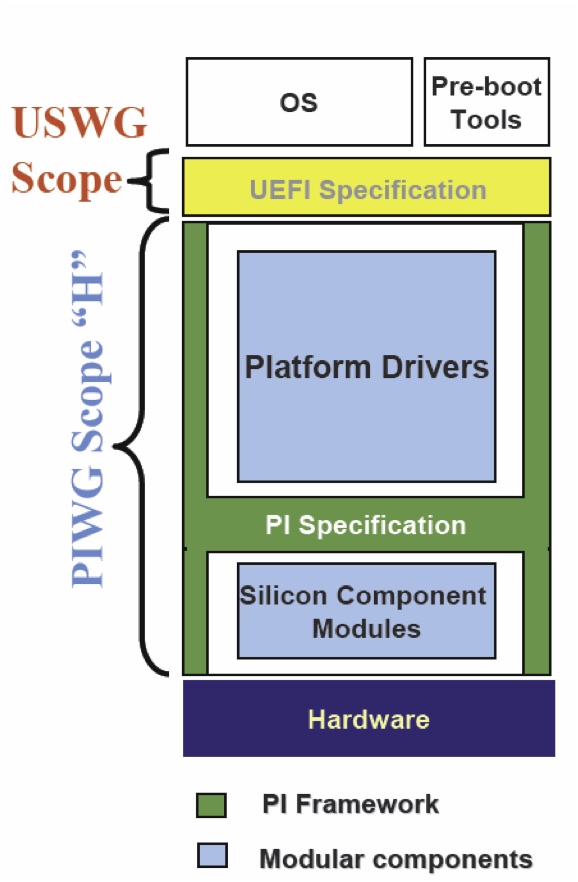
Acronyms And Glossary
The EFI and Framework Open Source Community lives within a fairly complex world of acronyms, terms, etc. Hopefully this page helps clarify some of those and provides a good reference.
ACPI Advanced Configuration and Power Interface. See <www.acpi.info>
AL Afterlife phase. Also known as the "power down phase."
AML ACPI Machine Language
API Application Program Interface. Programmatic interfaces for the firmware (not Win32-type OS-level APIs).
a priori file A file with a known GUID that contains the list of DXE drivers that are loaded and executed in the listed order before any other DXE drivers are discovered.
Artifact Something tracked in Project Tracker
ASL ACPI Source Language
Attribute A field of something tracked in CEE Project Tracker
BA Boot Authorization
BBS BIOS Boot Specification
BDS Boot Device Selection phase
BFV Boot Firmware Volume. Code (i.e., PEI and PEIM code) that appears in the memory address space of the system without prior firmware intervention. See also FV.
BIS Boot Integrity Services
BIST Built-in self test
BLT Block Transfer (pronounced "blit" as in "slit" or "flit"). A series of functions that form the basis of manipulation graphical data. The operation used to draw a rectangle of pixels on the screen.
BNF Backus-Naur Form. A metasyntactic notation used to specify the syntax of programming languages, command sets, and the like
BootDevice The device handle that corresponds to the device from which the currently executing image was loaded
BootManager The part of the firmware implementation that is responsible for implementing system boot policy. Although a particular boot manager implementation is not specified in this document, such code is generally expected to be able to enumerate and handle transfers of control to the available OS loaders as well as EFI applications and drivers on a given system. The boot manager would typically be responsible for interacting with the system user, where applicable, to determine what to load during system startup. In cases where user interaction is not indicated, the boot manager would determine what to load and, if multiple items are to be loaded, what the sequencing of such loads would be.
Boot Services The collection of interfaces and protocols that are present in the boot environment. The services minimally provide an OS loader with access to platform capabilities required to complete OS boot. Services are also available to drivers and applications that need access to platform capability. Boot services are terminated once the OS takes control of the platform.
BSD Berkeley Software Distribution
BSP Boot Strap Processor - typically the processor that will execute SEC and PEI
COFF Common Object File Format. An (originally) Unix *-based file format that is now recognized under several OSs. The format uses one or more header fields followed by the section data for the file
Compatibility16 A traditional legacy BIOS with the POST and BIOS Setup code removed. Compatibility16 BIOS code executes in real mode
CompatibilityBIOS The combination of both EfiCompatibility and Compatibility16
CompatibilitySmm Any IBV-provided SMM code to perform traditional functions that are not provided by EFI
CRC Cyclic Redundancy Check. A fixed-size error checking code appended to the end of a block of data (file) that is based on the content of the file
CRTM Core Root-of-Trust Module
CSM Compatibility Support Module. The combination of EfiCompatibility, CompatibilitySmm , and Compatibility16. Portion of the Framework that allows compatibility with non-EFI compliant operating systems to run on Framework firmware
CVDR Configuration Values Driven through Reset
Depex Dependency expression. Code associated with each Framework driver that describes the dependencies that must be satisfied in order for that driver to run. Controls order of execution in a Framework dispatch of PEIM and DXE drivers
DispatchEntry Point The entry point that the dispatcher invokes
Driver Modular chunk of firmware code that supports chipset or platform features. bReusable in multiple system contexts
DXE Driver Execution Environment phase
DXE Foundation A set of intrinsic services and an execution mechanism for sequenced control of driver modules
DXE Services Services, such as security services and driver services, that are usable by DXE drivers
EfiCompatibility EFI code that corresponds to EFI compatibility drivers, code that generates data for compatibility interfaces, or code that invokes compatibility services.
EDK EFI Developer Kit
EPL Eclipse Public License
Extensible Firmware Interface (EFI) EFI is a specification that defines the interface between an operating system, option ROMs, and platform firmware. EFI was originally invented by Intel as the Intel(R) Itainum BIOS replacement. EFI is now owned by a industry non-profit collaborative trade organization called The UEFI Forum.
FAT File Allocation Table
FAT32 FAT32 File System Driver
FD Firmware Device. A persistent physical repository that contains firmware code and/or data and that may provide NVS. For the purposes of this architecture specification, the topology of bFDs should be abstracted via bFVs.
FFS Firmware File System. A binary storage format that is well suited to firmware volumes. The abstracted model of the FFS is a flat file system
Firmware Device See FD.
Firmware Volume See FV.
FIT Firmware Interface Tableb.( Itanium systems only)
Font A translation between Unicode weights and glyphs. This "M" and this "M" and this "M" represent the same weight but in different fonts
FoundationCode The core interoperability interfaces between modules and in the Framework
FPSWA Floating Point Software Assist. (Itanium systems only)
Framework short for Intel® Platform Innovation Framework for EFI
FS Firmware Store. The abstracted model of the FS is a flat "file system" where individual files are SUMs
FV There are one or more FVs in the FS. The FV containing the "reset vector" is known as the Boot Firmware Volume (BFV). A FV is a simple Flash File System that starts with a header and contains files that are named by a GUID. The file system is flat and does not support directories. Each file is made up of a series of sections that support encapsulation.
GCD Global coherency domain. The address resources of a system as seen by a processor. It consists of both system memory and I/O space
glyph The graphical representation of a single Unicode weight
Globally Unique IDentifier (GUID) Globally Unique Identifier. A 128-bit value used to differentiate and name services and structures.
HII Human Interface Infrastructure. Repository of configuration and translation information for localization. Typically used with boot manager and shell to provide a localized user interface.
HOB Hand-Off Block. A structure used to pass information from one boot phase to another (i.e., from the PEI phase to the DXE phase)
IBV Independent BIOS Vendor
IFR Internal Forms Representation. A binary encoding of forms-based display content and configuration information
IHV Independent Hardware Vendor
IME Input Method Editor
Intrinsic Services Services, such as security services and driver services, that remain available after the phase during which they are instantiated
IPL Initial Program Load. An architectural PEIM to PEIM interface that starts the DXE phase
IPMI Intelligent Platform Management Interface
ISO 3166 An association between a country or region and a two or three character ASCII string
ISO 639-2 An association between a language or dialect and a three character ASCII string
Localization Concepts by which an interface is made useful to users speaking different languages and from various cultures by adapting the interfaces to the user. "STOP" in English would be "ALTO" in Spanish and "СТОП" in Russian. Alphabetic on keyboards are local to the language and may be local to the country the keyboard is localized for. For example, a French keyboard in France is different from a French keyboard in Canada.
MCA Machine Check Architecture
MDE Module Development Environment
NMI Non-maskable Iinterrupt
NRAM Nonvolatile Random Access Memory
NVS Nonvolatile storage. Flash, EPROM, ROM, or other persistent store that will not go away once system power is removed
ODM Original Device Manufacturer
OEM Original Equipment Manufacturer
OpROM Option ROM
PAL Processor Abstraction Layer. A binary distributed by Intel that is used by the 64 bit Itanium processor family
PCI Peripheral Component Interconnect. See <www.pcisig.com> for more information.
PCR Platform Configuration Register
PE/COFF PE32, PE32+, or Common Object File Format. A defined standard file format for binary images
PEI Pre-EFI Initialization phase. Set of drivers usually designed to initialize memory and the cpu so that DXE phase can run. sually the first bset of code run starting from reset.
PEI Foundation A set of intrinsic services and an execution mechanism for sequenced control of PEIMs
Pre EFI Initialization Module (PEIM) Pre-EFI Initialization Module. Modular chunk of firmware code running in PEI that supports chipset or platform features. Reusable in multiple system contexts.
PEI Services Common services that are usable by PEIMs
PEIM to PEIM Interface (PPI) A C structure named by a GUID that is published by one PEIM and consumed by another. The C structure can contain data and member functions. It differs from a Protocol in that it may have to function prior to memory being available and parts of the PPI could be in read only memory.
PHIT Phase Handoff Information Table. A HOB that describes the physical memory used by the PEI phase and the boot mode discovered during the PEI phase.
PIC Position-independent code. Code that can be executed at any address without relocation
POST Power On Self Test
Protocol A C structure named by a GUID that is published by one EFI or DXE driver and consumed by another. The C structure can contain data and member functions.
Reverse Thunk The code to transition from 16-bit real mode to native execution mode
RSD_PTR ACPI definition: Root System Description Pointer
RT or Runtime phase For EFI and the Framework this is after exit boot services has executed and the OS is in control of the system.
Runtime Services Interfaces that provide access to underlying platform-specific hardware that may be useful during OS runtime, such as time and date services. These services become active during the boot process but also persist after the OS loader terminates boot services.
SAL System Abstraction Layer. (Itanium systems only)
SALE_ENTRY System Abstraction Layer entry point. (Itanium systems only)
Sandbox The common properties of a driver or preboot environment that allow applications to run. These properties include a defined load image format and services that can run in the sandbox.
SEC SECurity Phase. Initial starting point for boot process, first code executed after hardware reset. Responsible for 1) Establishing root trust in the software space; 2) Initializing architecture specific configuration to establish memory space for the C code stack.
SMI System Management Interrupt
SMM System Management Mode
SOR Schedule on Request
SSE Streaming SIMD Extensions
SUM Separately Updateable Module. A portion of the BFV that is treated as a separate module that can be updated without affecting the other SUMs in the BFV.
Tiano Codename for the Intel Project to develop the Framework
TCB Trusted Computing Base
TCG Trusted Computing Group
TE Image Terse Executable image. An executable image format that is specific to the Framework. This format is used only in PEI and is used for storing executable images in a smaller amount of space than would be required by a full PE32+ image. Is a smaller more compact version of bPE32.
Thunk The code to transition from native execution mode to 16-bit real mode
UNDI Universal Network Driver Interface. Silicon specific driver in the preboot LAN stack that interfaces to SNP and PXEBC
Unicode A standard defining an association between numeric values known as "weights" and characters from the majority of the worlds currently used languages. See the Unicode specification for more information.
USB Universal Serial Bus. See http://www.usb.org for more information
VFR Visual Forms Representation. A high-level language representation of IFR
VM Virtual Machine
VTF Volume Top File. A file in a firmware volume that must be located such that the last byte of the file is also the last byte of the firmware volume
VT-UTF8 A serial protocol definition that extends VT-100 to support Unicode
Watchdog Timer An alarm timer that may be set to go off. This can be used to regain control in cases where a code path in the boot services environment fails to or is unable to return control by the expected path.
XIP Execute In Place. PEI code that is executed from its storage location in a firmware volume
EDK II FAQ Frequently asked questions about EDK II
UEFI/PI FAQ Frequently asked questions about UEFI/PI
Debug Faq
Debug frequently asked questions
Is there a way to get a list of or debug message of all the drivers that do not get dispatched? What is recommended
for DSC file and PCD configuration (Debug error level flag) to get a debug output list of all the drivers that were not dispatched?
Debug feature added DEBUG_DISPATCH – this shows the operation of the DXE and PEI dispatcher as it evaluates every dependency expression of every PEIM and DXE driver. It will check if the GUID is present or not and the result of the dependency expression as it runs through the dispatcher. Documented in the Debug Lib
Can Serial redirection used with Debug mode enabled?
A) On platforms where there is only one Serial port and if Source level debug is enabled then that port is used for the source level debug. (Build command line option of “-D SOURCE_DEBUG_ENABLE”) However, if the USB is used for the source debug port then it is possible to use the serial port for output of Debug print messages and console output.
B) For USB source debug you need a special cable: NET20DC which can be found at http://ajaystech.com/net20dc.htm
===Why do we still get debug print messages output to the serial port after changing the Conf\target.txt for “TARGET = RELEASE”? Shouldn’t this be turned off on a release build?=== A) There are different levels of debug to be considered. In EDK 1 there was a mix of levels of debug, DEBUG on and off was a combination of source level debug and debug print messages. EDK II has separated those concepts. The flag in the target.txt file “TARGET = RELEASE” only turns off the source level debug in the output files .pdb. The .pdb file points to the source code on your host machine which is part of the PE/off image and is part of the final Flash image. This makes it possible to do source level debug. B) Another debug concept with EDK II is the DEBUG and ASSERT macros that print messages to the console and serial port. These are controlled through the EDK II PCDs in the MdePkg:
- PcdDebugPropertyMask (bit mask to determine turning on/off for various macro features )
- PcdDebugPrintErrorLevel (bit map for various types of messages)
C) A third concept for using source level debugging with WinDBG uses build option: “-D SOURCE_DEBUG_ENABLE” – builds debug agent into your firmware. Check example in LakeportX64Pkg.dsc “ifdef”
It seems the way that the SMM Driver gets dispatched in EDK II has been changed. How does the SMM Driver get
dispatched? Is there any debug message to know which driver is loaded?
a) You need to select the debug lib in SMM core for report status code. It is SMM specific to go to serial port b) DEBUG_DISPATCH flag enable in SMM core for SMM dispatcher
Can we use the same serial port for FW debug sessions and for an OS channel session?
No. You can’t use same serial port for Firmware debug session & os channel session
What is the Macro CPU breakpoint?
CPU breakpoint –comes in as code to cause the processor to halt at that point.
The EDK II does not have a macro to generate a software breakpoint. Instead, the BaseLib in the MdePkg has a function called CpuBreakpoint(). When this function is called a SW breakpoint is generated. On IA32/X64 platforms, this is an INT 3.
Dec Faq
Frequently asked questions about DEC
How is DSC different from DEC vs INF?
The [EDK II Declaration (DEC)] file format supports the building, packaging, and distribution of EDK II modules. The [EDK II Platform Description file (DSC)] format describes a platform, which is (basically) a collection of DSC files. The [EDK II build information (INF)] file format describes how to build a single EDK II component, which generates a .EFI file.
For more info on DEC, please review the specification: https://tianocore-docs.github.io/edk2-DecSpecification/draft/
How many DEC and DSC files are in a build?
There is one DSC per Build but each package can have its own DSC. All packages must have a DEC file. The minimum content required in a DEC file is the [Defines] section. Also every platform package must have a DSC/FDF file to build a firmware image for the platforms FLASH/ROM. Non-platform packages typically have a DSC files to verify that the libraries and modules in that package can build properly for all supports CPU Architectures, all supported development Operating Systems, and all supported Tool Chains.
Can the DEC compile packages?
The DEC file declares Protocols, PPIs, GUIDs, Library Classes, and PCDs. It is not used directly to compile the contents of a package. Instead, the build system uses the declared contents of DEC files when building libraries/modules that reference the Protocols, PPIs, GUIDs, Library Classes, or PCDs that are declared in that DEC file. Module and Library INF files have a [Packages] section. The [Packages] section lists the set of packages that the Module or Library depends on to build. If a Module or Library uses a Protocol, PPI, GUID, Library Class, or PCD from a package, then the DEC file for that package must be listed in the INF file for that Module or Library.
What is DEC publishing?
The DEC of a package will publish protocols for consuming, PCDs that can be manipulated by other packages, Libraries and GUIDs. The DEC file declares Protocols, PPIs, GUIDs, Library Classes, and PCDs.
Depex Faq
Frequently asked questions about Depex
How is the Dependency expression (depex) generated, and what is is the relationship with libraries?
A) Dependency expressions are generated based on info from the [DEPEX] section of a module's .inf file.
B) The module .inf lists the library classes it depends. Those library classes are cross-referenced through the platform .dsc file to determine which library instances are needed to complete the link of the module. If the libraries also have [DEPEX] sections, those are “and-ed” with the modules.
C) [EDK I] did not have the concept of a Library Class – there were just libraries to link against. EDK I used the depx source file method with libraries. The developer’s job is easier in EDK II, since they don’t have consider inner dependencies on libraries.
D) To see the list of dependencies, use “build -Y DEPEX” to generate a DEPEX report.
Are dependencies static, or determined at execution time?
DEPEX is determined at execution time. It is also possible to use events to create a runtime dependency behavior, but this is a matter of individual implementation.
What are 'a priori' files?
The 'a priori' file is a special file that complements the dependency expression mechanism of PEI or DXE by stipulating a series of modules which need be dispatched in a prescribed order. This is an optional file, which provides a greater degree of flexibility in platform firmware. In general, the 'a priori' file is not required for most platform porting projects.
Differences Between Edk And Edk Ii
Note: The original EFI Development Kit (EDK) is no longer supported. This document is maintained for historical purposes. Please use EDK II for current UEFI development.
What are the differences between EDK and EDK II?
The main differences are in build architecture. The build description files (.dsc .inf, etc) have been enhanced. The EDK II build can understand EDK build description files, so an EDK II build can include EDK source code (with limitations). There are also build tool differences: EDK II supports a larger number of operating systems and tool chains.
EDK II has richer libraries (MDELIB, etc.), which makes the source code structure very different. EDK II also uses a package concept, so that the directory and file layout is different.
EDK II uses Platform Configuration Database (PCD) for parameterization and binary patch support, and supports. newer UEFI/PI specifications (see table below for more info).
EDK II provides compatibility with EDK-style source code using EdkCompatiblityPkg (ECP). However, ECP support is being deprecated in current platforms. This is possible because ECP provides binary compatibility for EDK through libraies and thunk code.
EDK II is also designed to work with Doxygen to generate design level specifications.
In addition, since EDK II supports later versions of the UEFI and PI Specifications, there are newer protocols that will be part of EDK II that do not exist in EDK.
Are there similarities between EDK and EDK II?
The Platform Initialization boot execution phases are similar. EDK and EDK II have a similar boot (SEC-PEI-DXE-TSL) and runtime flow. Protocol interfaces supported in both EDK and EDK II will be the same. EDK II can include EDK source code though the use of ECP.
The following table is a side by side comparison.
| EDK | EDK II | |
|---|---|---|
| Development OS | WinXP | WinXP/7/8/8.1/10, Linux, OS/X |
| Compiler/Linker | VS2003, VS2005, WinDDK | VS2003, VS2005, VS2008, VS2010, VS2013, VS2015, WinDDK, Intel, GCC4, GCC5, LLVM/CLANG |
| Build | nmake | nmake, gmake |
| Build Tools | C | POSIX C, Python |
| Target Platforms (open source) | NT32, DUET, | See EDK II Platforms |
| Distribution | ZIP Files – Entire Tree Packages with XML metadata | Packages Standard module distribution method (source/binary) XML – Allows packages/modules to be imported/exported to many build systems EDK Compatibility Package – Provides reuse of EDK source modules |
| Standards (UEFI) | EFI 1.10, UEFI 2.0, UEFI 2.1, Intel Framework, PI 1.0 | Focus on UEFI 2.3+/PI 1.2+ Spec Updates. Includes Support for EFI 1.10, UEFI 2.0+, PI 1.0+ & Intel Framework. See UDK2018 & EDK II for info on specific releases. |
| Library | binary .Lib files | Library Classes/Library Instances Maximize reuse of source code Use library instances to optimize for size or speed |
| Configuration Method | #define | Platform Configuration Database Maximize reuse of source code Allows platform developer/integrator to modify settings without modifying module sources |
How can you find out what has changed between releases?
The release notes will have a general summary of features and fixes for EDK II changes. See EDK II for the latest stable release and release notes.
In the past there were Libraries associated with PPI
EDK II does not use that model.
Differences Between Udk And Edk Ii
Frequently asked questions about the differences between UDK i.e. UDK2017 and EDK II
What is the difference between UDK and EDK II?
- EDK II is the open source project for which volunteers (contributors) participate in development. The tip of this project is being developed and updated constantly for fixes and enhancements.
- The UDK releases are NOT maintained by volunteer. Each UDK release is a fully validated implementation by Intel for a specific revision of the EDK II source. The latest UDK Release Notes denotes the git revision used for each of the validated UDK release.
- The UDK release contains a validated subset of the packages available from the EDK II project.
How do other 3rd party companies use UDK?
- Other 3rd party companies, including BIOS vendors use the UEFI conformance BIOS implementation based on the UDK release which Intel validates.
- See also the Intel UEFI community for more information https://software.intel.com/en-us/firmware/
UDK is stable
- It is NOT “always changed.” The last release of UDK was UDK2017 June 2017.
- The NEXT release of UDK is being discussed and will include any updates those that use it have requested to be included. The release cadence will likely be, perhaps, once every six months – completely dependent upon what feedback comes in from the open source community and customers that use it.
Differences Between Udk2010 And Edk Ii
Differences-between-UDK-and-EDK-II
Ebc Faq
Frequently asked questions about EDK and EBC
What is EBC?
EFI Byte Code (EBC) compiles UEFI driver C source code into an architecture-independent interpretive language instead of a native processor architecture (e.g. IA32, x64 or IPF).
Can you write a shell app in EBC?
Yes, it is possible. There are no known technical issues with using EBC for Shell Applications or UEFI Applications, but there be validation issues.
The UEFI Specification version 2.3, Section 2.6.2, item (19), states that the EBC interpreter is only required if a platform intends to support EBC drivers in containers for add in devices. This means that the EBC interpreter is optional and may not be available on all platforms. As a result, a Shell Application or UEFI Application that is compiled for EBC may not be able to run on all platforms.
Add-in cards need to support legacy images as well as EBC. Are there any conversion tools?
There are no tools to help convert a Legacy Option ROM sources or binaries to a UEFI complaint driver. Once a UEFI complaint driver is designed and implemented, it may be cross compiled to EBC. There are some compatibility issues that the UEFI driver writer must be aware of in order to implement a UEFI driver is C that is compatible with native mode compilers as well as the EBC compiler. Chapter 19 of the EFI Driver Writers Guide at UEFI Driver Writer's Guide describes porting considerations when using the EBC compiler.
EDK II FAQ
EDK II FAQ
Differences between EDK and EDK II
Differences between UDK2010 and EDK II
Build questions
Debug FAQ questions
DEC FAQ questions
ECP EFI Compatibility package questions
Execution order FAQ questions
GUID FAQ questions
NT32 questions
PCD questions
Shell questions
Virtualization FAQ questions
UEFI application questions
UEFI Drivers questions
USB stack questions
Is an a priori file checked first?
Yes
Is DXE single threaded now as PEI is?
Yes, could be multithreaded but the current EDK II implementation is single threaded. However, It is possible to use the MP Services Protocol in the DXE Phase to execute code on more than one processor. The MP Services Protocol is typically used by the CPU initialization code to propagate settings to all logical processors in the platform. The UEFI/PI services, Protocols, and PPIs are not designed with threading in mind. As a result, even though the MP Services Protocol provides a capability to run code on another logical processor, the code that is executed must be very carefully designed to not use any of the UEFI Boot Services, UEFI Runtime Services, or Protocols services that are not explicitly documented to be MP safe. In addition, there are many library services that make use of underlying UEFI Boot Services, UEFI Runtime Services, or Protocols, so many of the library services cannot be used from code running on a logical processor other than the BSP.
Is SMI handled by BIOS or OS BIOS?
The OS does not see SMI.
Is there a type Intel Development Environment IDE or are there Visual Studio solution files?
There was a VS .sol for EDK 1, no plan for EDK II.
What specifies flash organization?
The flash layout is defined in the .FDF file for the platform
Why does EDK II use library classes? Are there different instances?
EDK II’s implementation uses library classes as a way of tying different implementations to the same library name. This will resolve reference and make it so the Firmware developer can map the implementations at different sections of the Boot sequence. This is done because the implementation may differ for PEI vs DXE or DXE vs Runtime, etc.
The primary benefit is that code can be highly portable and reusable between different phases. For example, code written originally for DXE can be rebuilt in PEI without requiring modification. There are limitations, but there are far fewer differences visible to a programmer if libraries are used properly.
Is there an example of VFR?
Yes, there is an example in EDKII in MdeModulePkg\Universal\DriverSampleDxe. The sample Vfr.vfr describes a sample forms, check boxes, action buttons, and etc. that can be drawn in HII
When Recovery runs what part of the firmware gets updated on the UEFI target system?
Recovery is invoked during PEI phase and it will look for an image on some media, typically USB thumb drive for the file whose name is defined in the .fdf file.”. The .fdf file defines the flash layout and each platform gets to define what parts of the FLASH device are updatable or not. For example, the recovery code will update the main part of the flash device for what might be defined as “FVMAIN” in the .Fdf file with this image. The other sections of the flash device would remain intact.
What do the Version numbers mean for Package and platforms in the build description files for EDK II?
A package is identified by a combination of the PACKAGE_GUID and PACKAGE_VERSION. Every time a new version of a package is released, the PACKAGE_VERSION must be set to a higher value. The package owner gets to decide when the major or minor parts of the version value are increased. If a non backward compatible change is made to a package, then a new PACKAGE_GUID must be generated, and the PACKAGE_VERSION values can be restarted with a low value determined by the package owner.
What does EDK II Flash mapping tool do?
The flash mapping tool will get platform, flash and module information from target.txt,platform.dsc, flashmap.fdf, package.dec and module.inf. it will generate Ffs, Fv, FD and Section data depending on command line options. The tool will generate a FV directory which includes a FFS directory, Fv file, Fv INf file and Fd file. The FFS directory contents all modules directory which contents Ffs files and section files. All output of Flash tool output will be in FV directory.
How do I convert non-EFI oproms or Legacy ROM to UEFI oproms?
There are no tools to convert a Legacy Option ROM in source/binary form to a UEFI Driver. There is no such thing as a “UEFI oprom”. There are PCI Option ROMs, and the PCI Specification defines the binary layout of a PCI Option ROM that may contains multiple images. These can be Legacy Option ROM images, UEFI Drivers, and many other image types. The EfiRom utility simply follows the PCI Specification for the binary layout of PCI Option ROMs and provides the ability to put multiple images into a single PCI Option ROM. The image types supported by the tool are Legacy Option ROM images and UEFI Drivers.
What about the libraries with EDK II?
EDK II makes use of libraries to allow different implementations for the same functionality. EDKII introduces the concept of Library Class/Library Instance. Library class is a set of standard interfaces for common support routines, and library instance supplies the implementation of these interfaces. Platform integrator can select different implementations upon various application scenarios.
Does EDK II support ASL code?
EDK II has full support for ASL compilers from Microsoft and ACPICA. The EDK II has include files for ACPI Specifications up through ACPI 4.0. These include files are in /MdePkg/Include/IndustryStandard/Acpi.*. The UDK 2010 supports a number of reference platforms including Lakeport, Stoutland, and Richford. All of these platforms have source modules for the ACPI Tables and ASL code required for these platforms to boot ACPI complaint operation systems.
Does EDK II address Legacy USB?
No, BIOS vendors provide that
What does the library code call?
Library functions are either full implementations of the library function with no additional calls, or a library function may call other library functions or services. It is up to the library implementation to decide if it needs to call another library or service or not.
What is recommended for compiling drivers and applications with 64bit?
Since the build requires the use of at least one .DSC file the OVMF package could be used as a platform package to insert a driver or applications for building. Then to just build that driver or platform if you invoke the build in the directory where your driver or application resides, then just your driver or application gets built.
Add the path to your Drivers and Applications INF files to your DSC file in the [Components.X64] section. When the build is started for that DSC file, the newly added Drivers and Applications will be built for X64 and the generated .EFI files will be placed in the build output directory. If you want the Drivers and Application placed in a FLASH/ROM image, then the paths to the INF files will also have to be added to your FDF file.
For Lib classes (E.G. debuglib) how do you know which packages go with which library class?
Search INF Libclass = . . .
In the FDF what is the list of order for final image?
Typically the order listed is order of appearance
How do you create additional FDF segments?
The FDF Spec should have information on specifying in the FDF for a platform. See EDK II Specifications
Any formal forum?
Yes, Join the Sourceforge and sign up for the developer for EDK II. http://sourceforge.net/apps/mediawiki/tianocore/index.php?title=Mailing_Lists and subscribe to the mailing lists.
What happens when there is no more temporary RAM?
Running out of temp RAM could cause problems
The results are not predictable. Temporary RAM is used for both the Stack and for storing HOBs. These two regions grow towards each other. If they overlap, then the most likely scenario is that the Stack will corrupt HOBs, and on a build with DEBUG() and ASSERT() messages enabled the next time the HOB list is accessed, an ASSERT() will fire.
What is the Macro CPU breakpoint?
CPU breakpoint –comes in as code to cause the processor to halt at that point.
The EDK II does not have a macro to generate a software breakpoint. Instead, the BaseLib in the MdePkg has a function called CpuBreakpoint(). When this function is called a SW breakpoint is generated. On IA32/X64 platforms, this is an INT 3.
Can we use the same serial port for FW debug sessions and for an OS channel session?
No. You can’t use same serial port for Firmware debug session & os channel session
Is there a prescribed method for adding an embedded legacy option ROM to be loaded for legacy boot?
The code to support this is part of the file PciPlatform.c found in the platformX example in the directory: R8platformX Pkg\Platform\IntelXpg\platformX\PciPlatform\Dxe
Basically, the Option ROM is included in the table (mPciOptionRomTable) where each embedded ROM is defined by: File Guid, and PCI Vendor and Device ID.
In the Procedure:
EFI_STATUS
EFIAPI
GetPciRom (
IN EFI_PCI_PLATFORM_PROTOCOL *This,
IN EFI_HANDLE PciHandle,
OUT VOID **RomImage,
OUT UINTN *RomSize
)
A found device is checked against the table, and if there is an Option Rom available, a pointer to the Rom image is provided for load.
Is there documentation or a guide on the IA32FamilyCpuPkg as far as what needs to be done for the different
processor support?
There is not a lot of document but the one to modify the most is the CpuMpDxe driver
Is there any other Native EDK II platform available?
DUET, OVMF
Is there any porting guide available?
There is training material that has a high level list of the porting the different phases but there is no EDK I to EDK II porting guide.
How does the Intel® BLDK interact / interface with EDK II?
Intel® BLDK has EDKII within it. The biggest technical difference between Intel® BLDK and EDK II are that some of the options in the Intel® BLDK are routed to the VPD area of the platform which further enables binary editing. Some of the same options are also part of EDK II in that they are extracted by the PCDs but where they are stored may be different.
Is there a template for the BSF file but there is not a way to create one from scratch?
No, most take old BSF and then port it to a new platform. There isn’t a tool in existence to do one from scratch.
What is the biggest difference in the Intel ® BLDK vs. EDK II?
The biggest difference has to do with binary editing ability. Also reduced functionally (e.g. Intel® BLDK will not have CSM support )
What does “EFI API” mean and why?
A) It is used for function prototypes and declaration. It is for the source style for EDK II.It means that this function follows the calling convention as described by chapter 2 of the UEFI spec. Calling convention described for IA32, X64, IPF, and ARM. This forces the compiler to follow that exact calling convention for Boot services, Runtime services, also for Protocols and PPIs need to have EFI API. Internal worker functions do not need the EFI API.
B) MSFT vs UEFI calling conventions are similar so they would work.
Why do we have to put GUIDs and PPI, Libraries have to be under the /Include directory
There is no assumption from the build tools on where things are located but for design and consistency there is a coding style of putting them under the /Include directory.
Can a Package have multiple token spaces? And can they be shared across multiple packages? For instance is it
possible to have 5 tokens in 1 package and 5 in another?
a) Yes, packages can have multiple token spaces. b) Because token space is a GUID with a name, and also a token (32 bit ) associated with it. It is assumed to only be part of one package. We would want to avoid splitting tokens across multiple packages because of coordination issues.
What are the different Packages in EDK II and what are their inner dependences. Can you give a brief description of
the packages?
There it is supposed to be DEC has file header that has a description about the package and what the package is. We do Doxygen for DEC which will create a CHM and a description of the package. Inf has the description of modules and what each module does (what it consumes what it produces) EDK II may not have all the documentation and descriptions may be lacking. The plan is to improve over this over time.
Is there an example for read memory and or Memory mapped IO functions? Are there 2 separate calls for 32 and 64 bit?
There is an IO Library that supports both port IO and memory mapped IO and you give the exact size that you want to do the access (e.g. 8 bit, 16 bit, 32, etc). There are also a number of helper functions (ORing, masking,..) There is also a PCI library for doing PCI access.
Is there any EDK I code in the EDK II firmware?
No, There can be EDK I with the Edk Compatibility Package( ECP). EDK II can have EDK I if the ECP is used. ECP allows the building of EDK II with EDK I modules in the EDK II build base. ECP allows for EDK I to be brought up to the Latest UEFI Specs 2.3 and PI 1.2 . ECP does the translations from specs.
What is the meaning of the different status EFI Status vs other Status code?
EFI Status is related to the UEFI Spec “EFI Services” which is part of the DXE phase of the boot flow. One of the goals with the libraries was that there is a specific class of libraries that has a module type is “Base”. What is meant by “Base” is that library is compatible everywhere (SEC, PEI, DXE, SMM, etc.).To do this it cannot make any EFI assumptions so a subset of the EFI status codes was chosen for “return Status”.
Is there a doc template for listing dependencies?
Yes, – put this in the Module .INF dependences
Is there a good example of .Inf.?
MdeModulePkg\Application\HelloWorld\HelloWorld.inf
Is there a good example in the mde pkg?
MdeModulePkg\Application\HelloWorld\HelloWorld.inf
What is there in EDK II relating to the FV and COU microcode patch?
Not a way to just change the patch. It has to be part of the build. There is nothing to patch the .FD location. It needs to update the .fdf file. There has been a request for a tool to do this.
Is there a tool that can operate on a binary image?
The only type of information that can be patched in a binary image is of type PCD VPD (vital product data) that go into an uncompressed section of the binary/ROM image as defined in the .FDF file. Post Build. The only other type is Patch able in module that allows you to adjust values within a PECOF image within a PEIM or DXE driver. During build
Is the Dispatch order of modules recorded?
The report status code is the correct method. But this is not in place for the a priori files. To work around this, just put minimum to get the report status code available and working.
-The order will be with the DXE dispatcher. The order of the protocols will be the same as by using “dh” from the shell
-This is not available with PEI.
Suggestion is adding the dispatch order to the end of the Pei and Dxe. It reports status of the exact order
Since a lot of boards no longer have a serial port can AMT be used for console redirection port?
This is possible but since AMT shows up as PCI device there are issues with serial on PCI because it can init early but the resources might not be the same when the PCI Bus driver enumerates so this method may lose connections.
How do you assign resource?
We are currently working on another library for covering a generic PCI device to manage the redirection port this.
What are the Core version to match which spec versions of EDK(s)?
EDK II is at the spec level: UEFI 2.3 / PI 1.2 Spec implementation – EDK II builds can use: EDK Compatibility Package (ECP) – with EDK 1117 (EDK 1.01) that are at the spec level: UEFI 2.0 and Intel Framework 0.9
How do I burn a CD that is bootable (IA32.ISO)?
The easiest way to make a fedora uefi cdrom/dvdrom is to use their boot.iso install image. It is buried on their site though Simply burn the boot.iso to a cdrom or dvdrom and boot from your uefi system (in the boot manager select EFI DVDROM/CDROM boot)
The following location is present on all mirrors (IE at univ of Oregon) boot.iso Should also see the efidisk.img and efiboot.img in the same directory. http://mirror.uoregon.edu/fedora/linux/development/14/x86_64/os/images/
or
http://ftp.linux.ncsu.edu/pub/fedora/linux/releases/14/Fedora/x86_64/os/images/
so your favorite mirror /fedora/linux/development/14/x86_64/os/images then look for boot.iso and burn it with your burner software. If you want to make a usb stick fedora EFI bootable or want to do a netboot install see below. Minimal boot image method from fedora 14 docs.
http://docs.fedoraproject.org/en-US/Fedora/14/html/Installation_Guide/Making_Minimal_Boot_Media.html On the web there are 3 methods to install UEFI x64 fedora 14 to usb sticks:
http://blog.fpmurphy.com/2010/10/methods-to-uefi-install-fedora-14.html
For Ubuntu goto their cdimage to get the .iso images http://cdimage.ubuntu.com/
desktop would be maverick release
http://cdimage.ubuntu.com/releases/10.04.1/release/
ubuntu-10.04-dvd-amd64.iso 29-Apr-2010 15:28 4.1G Install/live DVD for 64-bit PC (AMD64) computers (standard download)
Efi And Framework Open Source Community Faq
The EFI and Framework Open Source Community FAQ
Last updated December 28, 2010
General Overview
Q: What is the EFI and Framework Open Source Community?
A: The EFI and Framework Open Source Community is a web-based collaborative software development community, initiated and financed by Intel, managed by CollabNet and open to the public. The main purpose of the communityis to provide a home for Open Source projects that focus their efforts on the Intel Platform Innovation Framework for EFI, or Framework for short. The Framework is an implementation of the Unified Extensible Firmware Interface (UEFI) 2.0 (or later) and the Platform Initialization 1.0 (or later) specifications. The primary project on the site is a development kit to enable platform firmware engineers to write, build, debug and test drivers, option ROMs, and EFI applications within the Framework's pre-boot environment.
Q: Is there any cost associated with using the EFI and Framework Open Source Community?
A: No, there is no fee to participate in projects on the EFI and Framework open source community website. The site hosting and maintenance fees are paid by Intel, but anyone is allowed to utilize it to build software. We only ask that your work be open-source and related to the EFI initiative.
Q: Can I develop proprietary products using the EFI and Framework Open Source technology?
A: Yes, and you are encouraged to do so, the EDK was developed for that purpose. All BSD-style licenses allow development of either continued open source style products or proprietary products.
Q: Can I develop proprietary products using the EFI and Framework Open Source site itself?
A: As an open source site, the EFI and Framework open source website does not support the hosting of proprietary projects. All code submitted to this website must be open-source. You can obtain a list of typical open source licenses from the Open Source Initiative.
Q: Is the EFI and Framework Open Source an open-source BIOS?
A: No, the EFI and Framework open source is not a BIOS, it is a site that houses projects related to platform firmware.
Q: Where can I get a BIOS based on the EFI and Framework open source community's technology?
A: Several leading BIOS vendors have developed products based on UEFI technology (some are members of this community). See the links on the homepage for possible vendors.
Q: Does the EFI and Framework open source community website basically containing Intel's "Framework" code?
A: The EFI and Framework open source community website is a software development site that hosts several projects related to the UEFI specification. The EDK project is home to the Foundation portion of the Framework (the portion released open-source by Intel).
Q: How does the EFI and Framework open source relate to the UEFI Specification?
A: Tthe EFI and Framework open source community website hosts projects related to the implementation of the UEFI specification, with special focus on projects related to the Framework, Intel's recommended implementation of UEFI.
Q: What is Intel's involvement in the site?
A: Intel provides financial backing for the site as well as guidance and input into community planning. In addition, they also maintain some of the projects. As the site matures, it is Intel's hope that other stakeholders get involved in the oversight of the EFI and Framework open source community.
Q: Who uses the EFI and Framework open source community's technology?
A: Development is of interest to Independent BIOS Vendors (IBVs), Independent Hardware Vendors (IHVs) pre-boot tool vendors and Original Equipment Manufacturers (OEMs).
Q: What types of projects are available?
A: Originally, there was one major project on the site, the EFI Developer Kit (EDK) and another small project, the FAT-DRIVER was technically a project, but in reality is simply a component of the EDK that is housed in a separate code repository for licensing purposes. As the site has matured other projects have come into being, and more are expected to sprout up in the future.
Q: Why do I need to register to get access to the code, since the code is open-source?
A: Even though the code is open-source, it is still governed by a license (in this case a BSD license). Therefore, the EFI and Framework open source community website requires registration, part of which is a click through of a site-wide users agreement, which includes accepting license of projects hosted here. This way registered users can access any code on any project hosted on the EFI and Framework open source community website.
Q: If I register for the site am I no longer anonymous?
A: If you are registered but not a member of any projects (and you do not post any messages to any mailing lists or discussion forums), no other users can see your information, or that you are even registered. This allows users to remain anonymous until they are ready to participate, yet still be access virtually all areas of the site.
Q: How can I get involved in the EFI and Framework Open Source Community?
A: This website has a "community" project, which is a gathering place for registered users to collaborate around issues related to the EFI specification. The community project is located here. Join this project and check out the forums and mailing lists included in it. Only through your involvement can this community shape itself into something valuable to the external community of firmware engineers.
Q: Do you have a glossary of terms for EFI and Framework open source?
A: We have a web-page that explains various acronyms associated with the EFI effort, located here FAQ.
Q: How can I add to or correct this FAQ?
A: If you have additions, corrections, or suggestions for this FAQ, please send them to the site maintainers at faq@tianocore.org.
Getting Started FAQ
Q: What are the expectations of a member of the EFI and Framework Open Source Community?
A: Expectations of members depend largely on the member's goals. Where some users may simply be here to gain access to the EDK, others may be actual contributors to that project. Others may have their own projects hosted here. Any and all registered users should consider becoming active on the site, either through joining projects or sharing ideas and thoughts in the Community project. As with any open-source web site, the value of the EFI and Framework Open Source Community is a function of the quality of participation of its members. In terms of behavior, all members are expected to be sensitive to others and to the fact that our member base comes from a large variety of countries, cultures and languages.
Q: What if I only want to download the source code, and not contribute?
A: That's perfectly fine. One of the goals of this site is for the EDK to be easily accessible by the various stakeholders. If you have any problems accessing source code and can't find your answers on the site, please send a question to questions@tianocore.org
Q: How do I become a member of the EFI and Framework Open Source Community?
A: You can self-register for membership in the EFI and Framework Open Source Community , see the link in the upper-left hand corner of the homepage. To join individual projects, you need to request membership from the project maintainer; directions are on the project homepage. You don't need to be a member of a project to gain access to the source code, but only project members can participate in project activities (bug fixing, testing, project-level mailing lists, etc).
Q: Do I need any specific client-side tools to participate?
A: At minimum, you need a Web browser, email client, and Tortoise SVN client. There might be additional domain specific tools you need depending upon the types of development project you want to contribute to. For example, for the EDK project you will need other tools, which are explained in the EDK Getting Started Guide.
Q: Who do I contact for help or feedback?
A: There are various sources of help on the site, including site-wide Help, New User Forum, and project-level mailing lists and forums. If you can't find your answer through these resources send your question to the EFI and Framework open source community manager at questions@tianocore.org.
Security FAQ
Q: What will you do with my registration data?
A: Your registration data (name, company, email address) are captured purely to acknowledge your agreement to the Terms of Serviceof the site.
Q: If I register with this community am I opening myself up to more spam?
A: Not at all. Joining the EFI and Framework open source community website will not generate spam and in fact, joining the forums and most mailing lists is also a non-spam activity. Some mailing lists could generate a high-level of emails, such as "issues@.." and "commits@.." because mails are sent to those lists every time a bug is updated or a piece of code is committed. As a result most people don't join those lists, they just look at the archives if they have a question. Each project has a "dev" list, which has fluctuating levels of activity depending on how much development is going on. Users who are actively participating in the site will value these mails, while others may choose not to be members. There are many lists and forums on the site, so if you are confused, please post your question on the New User forum, it's sure to be a popular one.
Q: What is the EDK Project?
A: The EDK is the open-source part of the Intel Platform Innovation Framework for EFI (for a good overview of the Framework see <www.intel.com/technology/efi/efi.htm> ). The EDK includes the "Foundation Code" of the Framework, as well as sample drivers and project-specific build tools. The Foundation code represents the core interoperability interfaces between modules and the Framework. The PEI Foundation supports silicon-support modules that are required during the first phase of system initialization, and DXE Foundation supports drivers, including drivers that implement portions of the Framework like PCI and USB, and drivers for various devices on boards. The Foundation code is ‘the green H’ that Intel has shown in multiple IDF presentations on EFI.
Q: What is the FAT-DRIVER Project?
A: The FAT-DRIVER project houses the FAT32 Driver portion of the EDK. The only reason the FAT-DRIVER is a separate project is because it is released under a slightly different license than the EDK.
Q: How are the two projects related?
A: Since the FAT32 is essentially part of the EDK, these two projects are tightly coupled, with all issues, mailing lists and discussion forums located in the EDK project. The FAT-DRIVER project has links on its homepage that jump to the EDK project, which may create a bit of confusion. Just be aware of the project name on the page you're looking at and you'll keep it straight.
Q: What is the EDK license model?
A: The EDK is released under a BSD license from Intel, explained here.
Q: What is the FAT-DRIVER license model?
A: The FAT-DRIVER source code is governed by a BSD license, modified by Intel, explained here.
Q: Who is managing these projects?
A: At present an Intel development manager is responsible for managing these projects. In time the community will decide the best way to manage these projects, Intel is simply at the helm at the start to "get the ship out of the harbor".
Q: I just want to download the EDK source code, how do I do this?
A: Join the EFI and Framework Open Source Community Website then go here for a directory of zip files associated with either development or official releases of the EDK source code.
Q: How to I become part of the EDK contribution team?
A: First, join the EFI and Framework open source community. Then, go to the EDK project homepage and click on "Request Project Membership/Role". The role you should request is "observer" which is the standard entry-level role for project members. Upon approval of the EDK Maintainer, you will find the EDK project listed on your "My Pages" tab, and you'll immediately be able to participate. The project homepage has a link to the EDK Maintainer, who can help you get started.
Q: How do I get "promoted" within the EDK project?
A: Since the CollabNet platform has role-based permissioning, "promotion" means being given a different role within a project. Promotion within the EDK project is as it is with any typical open-source project, via meritocracy. Through meritocracy, members are given responsibility, access and permissions based on the value they bring to the project. If you are a key contributor to fixing bugs, updating documentation, creating new enhancements, you will be "promoted" quickly. In a nutshell, its up to you how much of an impact you have on the project.
Q: Are there any particular areas that need contributor support today?
A: Since the project is fairly new, all areas are in need of participation. The EDK project maintainer would like to see interest in participating in testing, bug fixing, documentation and new feature development. The hope is that the project's virtual team's interest will drive participation in a natural direction.
Q: How can I find out how to use the EDK to build drivers?
A: The EDK project has an EDK Getting Started Guide, which helps users understand how to use the EDK to build drivers.
Q: How do I build the EDK?
A: In essence its as simple as downloading the source code, installing developer tools and running "nmake". Full details of how to build and use the EDK are explained in the EDK Getting Started Guide.
Q: I found a bug in the EDK, how do I report it?
A: The EFI and Framework open source community website uses a fairly robust bug-tracking system called "Project Tracker". See the The EFI and Framework Open Source Resolution Process for an overview of the flow, as well as a deeper explanation of how it works here. If you find a bug with the EDK (or have any EDK-related concerns, questions, issues, etc) your best bet is to post to the "Dev" mailing list in the EDK project. If your issue turns out to be a defect, either you or someone on the list can create a formal defect in the database.
Starting New Projects FAQ
Q: Am I permitted to start a project on this website?
A: If you have an idea for an open-source project related to the EFI specification and the Framework, you are encouraged to consider using the EFI and Framework open source community website as your hosting vehicle.
Q: What types of new projects are desirable?
A: New projects should be related to implementation of the EFI specification. Projects directly related to extending the Framework are especially desired.
Q: How do I submit a request for a new project?
A: If you have an idea for a new project please submit your request to the EFI and Framework Open Source community manager at Admin , and your request will be considered and responded to. If it's accepted you'll be given support in setting up and launching your new project.
Execution Order FAQ
Execution order
Can you see the execution order?
Yes with performance tools and on a specific platform with DEBUG enabled you can see the individual DXE Drivers through the serial redirection on a host machine running a terminal emulation application. The execution order is deterministic. For a given a platform configuration, the dispatch order will always be the same on every boot. If there are platform configuration changes, then the dispatch order may change.The serial output can also show the dispatch order of PEIMs and UEFI Drivers.
What tool collects all the drivers and what order does the driver dispatcher execute the drivers?
The mechanism is in the PI Spec. The concept is that for every driver there is a dependency expression - UEFI Drivers implied dependence on architecure protocoals and DXE Services. The PEI and DXE dispatcher is responsible for checking each driver's dependency and deterines whether to dispatch/execute each driver as it finds it in the flash device. If the driver's dependency expression does not evaluate to TRUE it will set that driver aside and continue to the next driver in the flash device. It is possible some drivers may not get dispatched.
Does it mean that Dispatched is accessing the flash searching for the dependency expressions?
The code will access the flash as little as possible because of the performance. For example, in PEI there is use of Cache memory if a driver's dependency is not TRUE.
How does PEI core allocate Cache for keeping track of PEIMs that do not get dispatched?
No eviction mode and set a side temp memory. PEI core will allocate memory.
There is another method called an a priori file. There can be one per Firmware volume. This will tell the dispatcher what order to dispatch list drivers in the order they need to dipatch them. This is a manual order. It does not need to be in any specific place in the FV. If it in the FV the dispatcher will find it.
GPT FAQ
Frequently asked questins about GPT
Are there tools to setup and create the EFI GPT partition?
Yes win7 installations set up GPT. Intel EFI technology has ‘partition utilities’ download: http://www.intel.com/technology/efi
Can an OS install be converted to EFI?
No, this must be on installation with a clean disk.
In reference to the figure in the UEFI 2.x Section 5.3.1 where does the Logical Block Address (LBA) LBAn exist on a disk?
LBAn is the last logical block on a disk and also stores the Backup GUID Partition Table Header’s fields. See section 5.3 UEFI 2.x for more details
In reference to UEFI 2.x section 5.3 GUID Partition Table (GPT) any impact to per due to GPT?
There are advantages for formatting hard drives with GPT:
- 128 Bit Unique Identifier and unique serial number
- Supports many partitions unlike MBR
- Uses a primary and backup table for redundancy.
- Support for greater than 2.2TB hard drives
When installing a UEFI aware OS when do you create the GPT Partitions?
If there is not a GPT partition then this must done on install. UEFI needs the GPT partition to create UEFI aware OS
Why would I need it (UEFI aware OS)?
To get the benefits of UEFI with the OS. One benefit is >2.2 TB hard drive support.
GUID FAQ
Frequently asked questions about GUIDs
How are GUIDs generated?
Globally” Unique Identity 128-bit quantity defined by Wired for Management WfM 2.0 specification on Intel Web site. There is a Web site where a GUID can be generated: http://www.guidgen.com Also, Microsoft Visual Studio also has a GUID generator. These unique identifies will and if you look at the wiki on this, the reality is that the probability of a collision is very, very, very small. From RFC 4122:
How do you decode all the GUIDs displayed on the console?
The output file Guid.xref gets generated as part of the build. This file will be located in the build output directory. This file will list all the GUIDs and the modules that are associated for each GUID Another way to decode GUIDs is to use a search utility on your WORKSPACE, and search only the .DEC and .INF files in your WORKSPACE. The DEC files contain declarations of all Protocols, PPIs, and GUIDs with a mapping between the GUID value and the C name for the global variable that is used from C sources. The INF files contain FILE_GUID defines for the GUID name of the FFS file that is stored in an FV.
DEC Examples [Guids]
## Guid specify the device is the console out device.
# Include/Guid/ConsoleOutDevice.h
gEfiConsoleOutDeviceGuid = { 0xD3B36F2C, 0xD551, 0x11D4, { 0x9A, 0x46, 0x00, 0x90, 0x27, 0x3F, 0xC1, 0x4D }}
[Protocols]
## Load File protocol provides capability to load and unload EFI image into memory and execute it.
# Include/Protocol/LoadPe32Image.h
# This protocol is deprecated. Native EDKII module should NOT use this protocol to load/unload image.
# If developer need implement such functionality, they should use BasePeCoffLib.
gEfiLoadPeImageProtocolGuid = { 0x5CB5C776, 0x60D5, 0x45EE, { 0x88, 0x3C, 0x45, 0x27, 0x08, 0xCD, 0x74, 0x3F }}
INF Example
[Defines]
INF_VERSION = 1.25
BASE_NAME = DiskIoDxe
FILE_GUID = 6B38F7B4-AD98-40e9-9093-ACA2B5A253C4
MODULE_TYPE = UEFI_DRIVER
VERSION_STRING = 1.0
ENTRY_POINT = InitializeDiskIo
Is there an easy way to decode the GUIDs including customer defined GUIDS and GUIDs defined in the Specs?
Request for a tool to manage this. Currently there is no tool to do this. A work around would be to use the Guid.xref file and import it to a spread sheet and compare to the GUIDs in the spec.
GUIDs used a Protocols, PPIs, and GUIDs in source code must be declared in a DEC file, and the DEC file supports comment blocks for GUIDs, so brief descriptions of the Protocol, PPI, and GUID are available. All the GUIDs from the Industry Standard Specifications are in the MdePkg, and are also in the Doxygen generated documentation for the MdePkg. The full .h file for each Protocol/PPI/GUID must be in the same package as the DEC file that declares the Protocol/PPI/GUID. Packages that are part of the UDK 2010 follow a recommended practice for the include file layout, so .h files associated with Protocols/PPIs/GUIDs can be easily found:
\` .dec Include`
Protocol\
<Protocol1.h>
<Protocol2.h>
Ppi\
<Ppi1.h>
<Ppi2.h>
Guid\
<Guid1.h>
<Guid2.h>
Is there a tool to track the chain of GUID to Protocol driver?
The build tool will generate a file xref file is built with every build GUID to guid name for that platform. This maps the GUID value to the name.
Where is the GUID name being used with a particular protocol?
Use the BUILD –Y to generate a report
What GUID maps to what drivers and how to find drivers installed?
The output file Guid.xref gets generated as part of the build. This file will list all the GUIDs and the modules that are associated for each GUID that get built into a platform. From the shell prompt the “Drivers” will list out the drivers installed.
Is there a data base for all the GUIDs installed in a platform?
Yes, from the EFI Shell prompt the “dh” command will list all of the handles with their associated GUIDs. In addition, the output file Guid.xref gets generated as part of the build. This file will be located in the build output directory. This file will list all the GUIDs and the modules that are associated for each GUID
Why is there a section GUID declared in the FDF file?
The GUIDed section is used for contiguous section guid, GUID keyword - used for signing- compression - encryption (encapsulation section -list of sections] as devided in the PI Spec.
Why use the GUID?
Because of where it gets mapped. Different compressions is another reason. The GUID has a cross reference in the tools to call used with tools_def.txt in the conf directory.
OVMF FAQ
- What is Open Virtual Machine Firmware (OVMF)?
- What source code license does OVMF use?
- What does OVMF provide?
- Are OVMF releases fully UEFI compliant?
- Does OVMF support legacy booting, legacy option ROMs, CSM?
- What quality level is the OVMF code? (Alpha, Beta, Production?)
- What virtual machines are supported by the OVMF firmware builds?
- Are only open source virtual machines supported?
- How can I use OVMF with a VM?
- Where is the source code to OVMF?
- If I work on a Virtual Machine, how can I make use of OVMF?
- Where can I find the current status and roadmap of OVMF?
- What build environments are supported by OVMF?
- Where can I ask additional questions and discuss OVMF?
- How can I contribute to OVMF?
- How do I build OVMF?
- How do I enable source level debugging with OVMF?
What is Open Virtual Machine Firmware (OVMF)?
OVMF is a project to enable support for UEFI within Virtual Machines. It is built upon the EDK II code base.
What source code license does OVMF use?
OVMF follows the EDK II project in using the open source BSD+Patent license. Some OVMF content is convered by additional licenses detailed in OvmfPkg/License.txt.
What does OVMF provide?
- Libraries and drivers related to virtual machines
- An entire firmware implementation with supports UEFI on open source virtual machines.
Are OVMF releases fully UEFI compliant?
While the goal is to be as fully UEFI compliant as possible, you should not assume that an OVMF release is fully UEFI compliant unless the particular release states full compliance.
For virtual machines, there are some challenging areas in achieving full UEFI compliance. For example, UEFI 'non-volatile' variables may be difficult to fully support in some virtual machine environments if a flash memory device is not emulated.
Does OVMF support legacy booting, legacy option ROMs, CSM?
No. While OVMF may have UEFI firmware drivers for some legacy hardware, there is no planned legacy compatibility for OVMF. One reason for this is that there is currently no open source CSM module which could be used within OVMF. Another reason is that we would like to use OVMF to help drive out some legacy assumptions which might be made by software layers above the system firmware.
What quality level is the OVMF code? (Alpha, Beta, Production?)
The quality level of the OvmfPkg within the edk2 source code repository may change over time. Therefore, the best way to determine the current quality level of the source repository is to look at the README document under the OvmfPkg source directory or ask the EDK II dev email list. Binary releases of OVMF may indicate a code quality level, and should also indicate the versions of the source code repositories used to produce that binary release.
What virtual machines are supported by the OVMF firmware builds?
Hopefully this will improve over time, but initially the QEMU virtual machine will be supported while emulating a IA32 (x86) or X64 (x86-64) based system. The README text file included under the OvmfPkg source tree should contain the most up to date list of supported virtual machine environments. The README text file included with binary releases should also document the supported virtual machine environments which are supported for that release.
Are only open source virtual machines supported?
We have chosen the BSD+Patent license to enable easy incorporation of any of the piece of our code within nearly any type of product. But, it is likely that the firmware images produced by OvmfPkg under edk2 will only support open source virtual machines.
How can I use OVMF with a VM?
Pre-built binaries of OVMF are available under the 'OVMF' folder in the 'Documents & files' area of the EDK II project. The binaries of OVMF are intended to replace the normal firmware/bios that a VM would use when booting the VM. The README file included in the downloaded archive file will explain how to run the OVMF firmware image with the supported VM.
More detailed instructions for running OVMF can be found on the running OVMF wiki page.
Where is the source code to OVMF?
The source code to OVMF is under the OvmfPkg directory within the EDK II source repository. Changes to other EDK II packages (directories) will be driven by the OVMF project as required.
If I work on a Virtual Machine, how can I make use of OVMF?
At the minimum, you can utilize OVMF as a sample platform for how a VM firmware can be built with EDK II. If you find that the OVMF platform and/or EDK II code base does not provide adequate support for building your VM firmware, please open a discussion on the EDK II dev email list.
Where can I find the current status and roadmap of OVMF?
Please look in the README file under the OvmfPkg source directory.
What build environments are supported by OVMF?
OVMF's goal is to support all the build environments which the main EDK II project supports. This includes support for building under the Linux, Mac OS X and Windows operating systems. Toolchain support includes GCC, Visual Studio (2003 or 2005), WINDDK, ICC (Intel Compiler) and GCC under CYGWIN.
If you are new to EDK II development, this page may help you get a build environment up and running. OVMF will also require an ASL compiler to be installed on the system. The Intel ASL compiler is compatible with many operating systems, and is available from http://www.acpica.org.
Where can I ask additional questions and discuss OVMF?
Questions and discussion related to OVMF should be directed to the EDK II dev email list.
How can I contribute to OVMF?
Please refer to the Getting Started page.
How do I build OVMF?
Refer to the README document under the OvmfPkg directory within the EDK II source repository or on the building OVMF wiki page.
How do I enable source level debugging with OVMF?
Please refer to:
- EDK II Source Level Debug
- How to debug OVMF with QEMU using GDB
- How to debug OVMF with QEMU using WinDbg
Platform Configuration Database (PCD)
Questions asked about PCDs
Where are PCDs specified?
PCDs are declared as part of the DEC, and referenced in a modules INF and a package’s DSC.
Are all PCDs stored as variables?
- PCDs of type FeatureFlag are declared as CONST variables in every module that uses that PCD
- PCDs of type FixedAtBuild are also declared as CONST variables in every module that uses that PCD
- PCDs if type PatchableInModule are declared as ‘volatile’ variables in every the module that uses that PCD.
- PCDs of type Dynamic/DynamicEx are global to the entire platform. There are 3 subtypes of Dynamic/DynamicEx. The first is VPD, which are Read-Only and is stored in an uncompressed section of the system FLASH/ROM. The second is HII, which are R/W and Non-Volatile, and they are mapped to an EFI Variable which is named by a GUID + UnicodeString + ByteOffset. The third is Default, which are R/W and Volatile, which means their contents are lost every time the platform is reset or power cycled.
Is there a Pcdget?
Yes, there is PCD Library call depending on the type and size of the PCD variable
Where are the rules for PCDs? Is it in a single spec?
The PCD Documentation is part of the Build description specifications. Such that there is a section in each of the DEC, DSC, FDF and INF specifications that list the syntax of the PCD for each type of spec.
Is there a PCD User Guide?
Not currently
The DEC files have a Token associated with each PCD entry. How is this token generated?
The package owner assigns a unique token with the PCD entries.
How is a PCD used to enable or disable drivers at build?
The FeatureFlag PCD can be used to enable or disable drivers during runtime. If the platform designer wants to not include the feature or driver then there are a couple of possibilities. Use different .DSC and .FDF files to have them removed. Another is to use “–D” with the build command line to pass macros into the build. There is an active feature request for PCDs to be used to enable/disable drivers at build time. This is a capability that will be made available in a future release of the EDK II.
Are PCDs supported within the ACPI and AML?
There minimal support with PCD and ACPI because the ASL complier is built as a separate part of the build process.
How automatic is the Platform coding?
Packages designed properly should be able to use and port by only adjust PCD values—hard-coded values require touching sources
Can we use PCDs for larger structures?
Nothing prevents using PCDs for large structures
Is there a Build time PCD that can be used to the setup screen?
Yes, Use DynamicHii PCD type that should reference the Varstore structure stored to efivariable—dynamic pcd –statement token space guid in token space, etc for that specific setting compute offset & put into DSC file
EDK 1 uses Macros to initialize array variables. How do you use fixed PCD in an array element in a library?
I’ve tried to use PCD Fixed at build but I get error using fixedPCDget32 in a library module. What is the scheme to initialize an array with fixed values in a library?
A) You cannot use a fixed PCD get call for a global structure or global initialization from a library. This is a limit from the PCD design. The reason is the PCD value can be set on a per module bases. For example if you have 5 modules linking for the same library the modules can override the values of the PCD. This was done for Build performance so that each library would be built only one time. The FixedPCDget is allowed to be used within a module but not within the libraries.
B) I recommend having portions of your library having global structures or variables – Pre initialize as much of the global you can that does not require the use of PCDs. Then introduce a library constructor and then in your code for the constructor you can use the FixedPCDGetnn to fill in the value as opposed to pre initialized in the data section
Is there a way to view the PCD data?
There is no GUI interface but the BUILD with “-Y PCD” option for the platform will create a report for that platform. It will show at the module level.
Is there Porting guide for what PCD values need to change?
The best way is to look at the Mdepkg .chm. It should list what the PCD is and it’s characteristics with descriptions of each. The .chm is created from the .dec file that defines the PCDs using the Doxygen tool.
When modifying PCDs within the token space for different products
When modifying PCDs within the token space for different products the different products will have the entire PCD token space for that package as opposed to just a few PCDs that would need to be changed per a product.
There are too many PCDs in the .chm. Is there any other means for documentation for porting/ integrating?
The .CHM is the package scope. The other aspect is distributing a module needs to have documentation for integration. Need to list dependencies for module. The documentation should follow at the module level and listing out the PCDs and their default working.
Pre-EFI Initialization (PEI)
Frequently asked questions about PEI
Can SEC & PEI be built independently into separate binaries?
Yes, using EDK II, EDK has a special build process for Sec. EDK II platforms each have their own SEC library code that could be built separately and then included in the EDK II build process.
In which phase would the TXT features get included?
While a few things in SEC phase are affected, most of the feature support I added to the PEI phase.
Are the PEI phases performed on Boot Strap Processor (BSP), what about APs?
The HW puts APs into Wait-For-SIPI at reset. Code running on the BSP must wake an AP to get the AP to run any code. This could be done in any/all of the PI Phases, but it is typically done in the DXE Phase when the DXE Driver that perform CPU initialization is executed.
What is done in SEC phase?
The best way to summarize SEC is to get the platform into a state where it can run C code. This typically involves initialing a stack in temporary RAM. For Intel processors, Set up the processor for NEM; basically establish temporary memory. Set up Processor registers. Go into protected Flat 32 bit mode. Set up the APs. Jump to PeiMain
Example PEI modules (detailed) driver list—can details be known before execution?
There is not a tool to determine the ordering before building or execution time (i.e. Priority list for ordering ) Example from Lakeport is PCD, ReportStatusCodeRouterPei, and StatusCodeHandlerPei.
Can PEI and Sec be Split into separate pieces?
It would be possible to include the Sec as a separate Binary. Normally Sec is a separate module that is part of the PEI stored in the recovery firmware volume.
What is shadow PEICore?
A PEIM binary image can be executed in place from its location in the firmware volume (FV) (Not Shadowed) or from a compressed component that will be shadowed after permanent memory has been installed. Shadowing does not require compression. It is possible to shadow a component that is not compressed, and we do this for the PEI Core itself.
The term “Shadow” originated in the Legacy BIOS (80386 timeframe), when the code stored in an eight bit wide ROM part was copied into the physical RAM (32 bit wide) to improve performance of the BIOS code.
Are Architectural PPIs marked differently than additional PPIs? Or a GUID?
Architectural PPIs are defined in the PI specification Vol. 1 with a defined set of GUIDs. Example of Architectural PPI, EFI_PEI_MASTER_BOOT_MODE_PPI, EFI_DXE_IPL_PPI, and EFI_PEI_PERMANENT_MEMORY_INSTALLED_PPI are all required PPIs
What does the memory map look like at the end of PEI phase?
There is a pointer, PEI Handoff Information Table (PHIT). PEI Memory Bottom and PEI Memory top are both stored in the PHIT. Memory is allocated from both the top and the bottom. Free memory is represented by pointers in the PHIT for both Free memory top and Free memory bottom. The Hand off blocks will also be pointed by the PHIT which will contain all the resource information discovered during the PEI phase. See § 4 PI Vol. 3 Spec
What is the minimal set of PEI drivers in a sequence of execution?
Is it known before execution? Basically, PEI needs to initialize PEI Core services, Discover Boot mode, and Initialize Memory. On a specific platform with DEBUG enabled you can see the individual PEIMs through the serial redirection on a host machine running a terminal emulation application. It is not know before execution the order or which PEIM will be invoked and it is non-determinant.
What is the PEI dispatch order if there are no DEPEX?
A Priori list can be used otherwise it will be the order in the FV per DSC/FDF definitions (these files order the creation and inclusion of the modules in an FV).
Does PEI support callbacks?
PEI does not have events like DXE, but uses PPI notification which is similar
Since PEI is 32 bit and DXE is 64 bit how do you determine which Library to use and / or call?
In general for all the Libraries and APIs it does not matter. It is a “C” call able interface and if you compile for 32 bit or 64 bit, you will get the library in either 32 or 64 bit. Itanium and the EFI Byte code compiler are also supported. Plus ARM on open source. There are a few “Base” libraries that CPU specific.
Shell FAQ
Shell questions
Can you write a shell app in EBC?
Yes, it is possible. Please check the ULA for the EBC compiler. 1 I believe that has the specific details on driver/app support. There are no known technical issues with using EBC for Shell Applications or UEFI Applications. This is mainly a validation issue. Another issue is that the UEFI 2.3 Specification Section 2.6.2 item (19), states that the EBC interpreter is only required if a platform intends to support EBC drivers in containers for add in devices. This means that the EBC interpreter is optional and may not be available on all platforms. As a result, a Shell Application or UEFI Application that is compiled for EBC may not be able to run on all platforms. Intel® C Compiler for EFI Byte Code Product In-Depth
Can we do shell within shell & script within script?
Yes, the shell can invoke nested instances of the shell and shell scripts can also invoke nested instances of other scripts
Is the location of scripts fixed?
No, Shell scripts can exist anywhere within a Fat file system on any media. If they are not in the CWD then the path to a script can be specified.
Can you add driver into your runtime from an external USB or other drive?
Yes, can boot to shell and load with shell’s load command—can be a BDS option or others.
Is there an event related to the efi shell?
No, but it is in Preboot time and after Architecture protocols.
Are there any signing tools for using in the EFI shell to sign a capsule of Firmware volume?
We provide a way from the enabling perspective by using a GUIDed section extraction and EDK II has tools to recognize a GUIDed section. This would enable Compression, Encryption and Signing. There are sources for tools in BaseTools CRC32 and LZMA compression. By looking a these examples a signing tool can also be used.
When is signing done and what about PEI and DXE signature checks
It is done at Build time, but it is possible to sign at boot time. For PEI and DXE signature checks it is possible as long as they are build with the appropriate architecture (E.g. 32 bit fore PEI and X64 for DXE)
What tool collects all the drivers and what order does the driver dispatcher execute the drivers?
The mechanism is in the PI Spec. The concept is that for every driver there is a dependency expression - UEFI Drivers implied dependence on architecture protocols and DXE Services. The PEI and DXE dispatcher is responsible for checking each driver's dependency and determines whether to dispatch/execute each driver as it finds it in the flash device. If the driver's dependency expression does not evaluate to TRUE it will set that driver aside and continue to the next driver in the flash device. It is possible some drivers may not get dispatched.
Does it mean that Dispatched is accessing the flash searching for the dependency expressions?
The code will access the flash as little as possible because of the performance. For example, in PEI there is use of Cache memory if a driver's dependency is not TRUE.
How does PEI core allocate Cache for keeping track of PEIMs that do not get dispatched?
No eviction mode and set a side temp memory. PEI core will allocate memory.
There is another method called an a priori file. There can be one per Firmware volume. This will tell the dispatcher what order to dispatch list drivers in the order they need to dispatch them. This is a manual order. It does not need to be in any specific place in the FV. If it in the FV the dispatcher will find it.
How do you add the new UEFI Shell 2.0 to the Nt32 in the UDK2010.SR1
You need to update the Nt32Pkg.dsc and the Nt32Pkg.fdf with the following:
Nt32Pkg.dsc
1) At the end in the [LibraryClasses.common.UEFI_APPLICATION] section add the following:
ShellLib|ShellPkg/Library/UefiShellLib/UefiShellLib.inf
FileHandleLib|ShellPkg/Library/UefiFileHandleLib/UefiFileHandleLib.inf
SortLib|ShellPkg/Library/UefiSortLib/UefiSortLib.inf
ShellCEntryLib|ShellPkg/Library/UefiShellCEntryLib/UefiShellCEntryLib.inf
PathLib|ShellPkg/Library/BasePathLib/BasePathLib.inf
2) At the end in the [PcdsFixedAtBuild] Section add the following:
# Update the PCD as follows using the UEFI Shell's 2.0 PCD:
gEfiIntelFrameworkModulePkgTokenSpaceGuid.PcdShellFile|{ 0x83, 0xA5, 0x04, 0x7C, 0x3E, 0x9E, 0x1C, 0x4F, 0xAD, 0x65, 0xE0, 0x52, 0x68, 0xD0, 0xB4, 0xD1 }
3) At the end in the [Components.IA32] Section add the following:
ShellPkg/Application/Shell/Shell.inf {
`NULL|ShellPkg/Library/UefiShellLevel2CommandsLib/UefiShellLevel2CommandsLib.inf` `NULL|ShellPkg/Library/UefiShellLevel1CommandsLib/UefiShellLevel1CommandsLib.inf` `NULL|ShellPkg/Library/UefiShellLevel3CommandsLib/UefiShellLevel3CommandsLib.inf` `FileHandleLib|ShellPkg/Library/UefiFileHandleLib/UefiFileHandleLib.inf` `ShellCommandLib|ShellPkg/Library/UefiShellCommandLib/UefiShellCommandLib.inf` `SortLib|ShellPkg/Library/UefiSortLib/UefiSortLib.inf` `HandleParsingLib|ShellPkg/Library/UefiHandleParsingLib/UefiHandleParsingLib.inf` `ShellLib|ShellPkg/Library/UefiShellLib/UefiShellLib.inf` `ShellCEntryLib|ShellPkg/Library/UefiShellCEntryLib/UefiShellCEntryLib.inf` `PathLib|ShellPkg/Library/BasePathLib/BasePathLib.inf` `!ifndef $(NO_SHELL_PROFILES)` `NULL|ShellPkg/Library/UefiShellDriver1CommandsLib/UefiShellDriver1CommandsLib.inf` `NULL|ShellPkg/Library/UefiShellInstall1CommandsLib/UefiShellInstall1CommandsLib.inf` `NULL|ShellPkg/Library/UefiShellDebug1CommandsLib/UefiShellDebug1CommandsLib.inf` `NULL|ShellPkg/Library/UefiShellNetwork1CommandsLib/UefiShellNetwork1CommandsLib.inf` `!endif`
gEfiShellPkgTokenSpaceGuid.PcdShellLibAutoInitialize|FALSE
}
Nt32Pkg.fdf
4) Add the following at the end of the # DXE Phase modules in the Nt32Pkg.fdf file
INF ShellPkg/Application/Shell/Shell.inf
5) Comment out by adding "#" at the begining of the line the EFI EDK shell 1.0 in the FILE section of the Nt32Pkg.fdf file
#FILE APPLICATION = PCD(gEfiIntelFrameworkModulePkgTokenSpaceGuid.PcdShellFile) {
# SECTION PE32 = EdkShellBinPkg/FullShell/Ia32/Shell_Full.efi
# }
UEFI PI FAQ
More information: UEFI-and-PI-Wiki | PI Boot Flow | PI
Frequently asked Questions about UEFI/PI
Build questions
Depex FAQ questions
GPT FAQ questions
GUID FAQ questions
HII questions
PEI questions
Shell questions
UEFI application questions
It seems as though UEFI is revolutionary given the scope of changes from legacy BIOS
The Implementation may seem like it is revolutionary since it is now in “C” instead of Assembly but once the structure of UEFI is understood it is then easier to see how UEFI is doing some of the same work as Legacy BIOS. In fact, the UEFI implementations are done with software design structures in mind.
Two other notes on this:
- UEFI / PI accounts for legacy BIOS through the CSM
- UEFI was originally a layer built on top of legacy bios giving the interfaces for UEFI option ROMs and UEFI Drivers.
Is there support for multiple processor architectures?
Currently there is support for the Intel X86 Family (IA32 and X64) as well as the Intel® Itanium® Processor Family (IPF). Other companies are supporting the ARM processor
What is the UEFI adoption rate of UEFI Platforms on the market?
Currently over 50% maybe somewhere above 70% as of 2010
Can Self Certification Tests (SCT) be extended?
Yes, the UEFI SCT User Guide has a section (5.3) on how to add test cases to the SCT. The SCT releases can be downloaded from http://uefi.org
Who defines Protocols?
The UEFI and PI specifications define many useful protocols available to be consumed by developers. If you are writing a driver there may be other protocols that your diver will produce. In general protocols are function calls with a well defined interface from either the UEFI or PI specifications.
What is the relationship between boot and Runtime services?
Boot services are available only until ExitBootServices() is invoked. Whereas Runtime services are available during boot and after ExitBootServices().
Runtime services are intended to provide additional support to the OS after the pre-boot environment is no longer relevant. SMM code on Intel Processors is considered Runtime code, by its very nature(it is not feasible to remove SMM code from SMM space one established. Ergo SMM code will remain resident after ExitBootServices().
What about boot and runtime Services in SMM mode?
The SMM runtime services are similar to the DXE foundation but SMM libraries would only contain SMM code.
SMM code on Intel Processors is considered Runtime code, by its very nature(it is not feasible to remove SMM code from SMM space one established. Ergo SMM code will remain resident after ExitBootServices().
Add-in cards need to support legacy image as well as EBC. Any conversion tools?
There are no tools to help convert a Legacy Option ROM sources or binaries to a UEFI complaint driver. Once a UEFI complaint driver is designed and implemented, it may be cross compiled to EBC. There are some compatibility issues that the UEFI driver writer must be aware of in order to implement a UEFI driver is C that is compatible with native mode compilers as well as the EBC compiler. Chapter 19 of the EFI Driver Writers Guide at http://developer.intel.com/technology/efi/dg.htm describes the porting considerations when using the EBC compiler.
Can you show the control flow from power-on to OS boot?
Yes, per the PI Spec the UEFI / PI firmware goes through the following phases:
- Sec – Security phase – Set up Temp memory
- PEI – Pre-EFI – Initialize Memory
- DXE – Driver Execution – Dispatch list of UEFI / DXE drivers
- BDS – Boot Device Selection –Run Setup
- TSL- Transient System Load – Run EFI Shell
- Runtime boot to the OS – Execute the OS loader
What is PI? Is it the same as legacy?
No, PI stands for Platform Initialization and the original Intel® Platform Innovation Firmware for UEFI Specification it evolved into the Platform Initialization (PI) Specification. PI describes the boot execution phases to encompass UEFI supported protocols and services.
There are UEFI defines services and there are PI Services. Do any of these services overlap and are there services?
The PI services are a super set of services so that the UEFI Services are all part of PI services. In addition there are some PEI services specific to PEI since PEI is not executing out of memory.
What are events?
UEFI events are constructs that are used to provide communication between UEFI modules.
Timer events are asynchronous. All other event types are synchronous.
UEFI Events are managed through UEFI Services. UEFI Events can be created and destroyed and are either in the waiting state or the signaled state. An UEFI image can do any of the following:
- Create an event.
- Destroy an event.
- Check to see if an event is in the signaled state.
- Wait for an event to be in the signaled state.
- Request that an event be moved from the waiting state to the signaled state.
Priorities between events?
Every event will have a Task Priority Level (TPL) associated with it. The TPL levels are
- TPL_APPLICATION
- TPL_CALLBACK
- TPL_NOTIFY
- TPL_HIGH_LEVEL
How does HW signal if not Interrupts (INTS)?
Instead, UEFI supports polled drivers. The most common use of events by an UEFI driver is the use of timer events that allows drivers to poll a device periodically. So any device I/O is done through polling.
So UEFI does not discover interrupt routing & program apics?
Discovery, yes but typically a UEFI Platform will only program these if it is going to boot a legacy OS. This resource information is however, discovered during PEI and DXE. It would later handshake to the OS through the CSM. Much of this is done at the platform level through the ACPI data structures.
How does UEFI know which is the boot device, so it can enumerate it? What if there is no user intervention?
The Boot devices are determined by the UEFI boot manager. The UEFI boot manager is a firmware policy engine that can be configured by modifying architecturally defined global NVRAM variables. The first boot device, is typically set by OEM, is in the UEFI NVRAM Variable BootOrder
Can C++ be used?
No, C++ has a larger footprint, and the UEFI environment does not support constructors and destructors. The “C” code can be used to do similar C++ things by writing specific algorithms in C. There is No C++ support. However, you can use C++ code as long as there are no global objects—do not use new .
How does No Eviction Mode (NEM) work?
For Intel X86 Processors early in the SEC phase the MTRRs are set up to define the stack just under 4G but in cache. The processor is then set to “No Eviction Mode”. Then the Stack pointer (SP) is set to a location in this memory.
This allow the Cache to be used for Data accesses, as if there were RAM at those addresses. The cache is not “flushed” (no eviction). When RAM is available, the cache can be evicted into the physical RAM space assigned for cache, thus providing a ‘seamless’ context change of CAR to RAM mode.
On Intel Itanium® Processor Family (IPF) Servers with Firmware interface table FIT – a table at an architected
location pointing to pal & sal components is it similar?
FIT on IPF is architectural. It is described in the public SDM for IPF. Describes the location of PAL/SAL. It is not related to NEM.
When there are multiple Firmware Volumes (FVs), what additional code is required?
The PI PEI core foundation already has a mechanism for handling multiple FVs. Multiple FVs is platform specific and would be described in a platform’s FDF file.
A platform specific PEIM has to declare the location of additional FVs for them to be known to the PEI Core. Once they are declared to the PEI Core, the PEI Core can dispatch PEIMs from them. The only FV that is known to the PEI Core when it is started is the Boot Firmware Volume (BFV). The BFV contains SEC and the PEI Core and one or more PEIMs.
Do some Servers have multiple FVs for redundancy?
Yes, this is maybe a platform policy and it would be platform policy of the mechanism for using the FVs for redundancy. That mechanism is not scoped within the PI spec.
Are there any limits on memory size?
Just 64bit address space . . .
What about TSEG?
TSEG would be platform specific and this information is passed in some HOB, EFI_SMRAM_HOB_DESCRIPTOR_BLOCK.
Are timers run off apics, . . . or implementation & cpu architecture dependent?
The method is really Implementation dependant, but in Intel architectures it models an 8254 timer API
Is it a global time for all events?
Yes.
Referring to PI Vol. 2 Section 10.11 DXE Dispatcher State Machine what is SOR? How does it work?
SOR Stands for Schedule On Request. If the SOR opcode is present in a DXE driver’s dependency expression, then the DXE driver is placed in the “Unrequested” state. If the SOR opcode is not present in the DXE driver’s dependency expression, then the DXE driver is placed in the “Dependent” state
When SOR is present, the module will not be executed until another driver specifically requests that driver to be run. This is done through the DXE Service called Schedule(). See PI 1.2 DXE CIC Section 7.3
Is NMI the same?
It depends on NMI is mapped in the platform. In the PC environment, the NMI is part of the standard hardware interrupts of the processor. In fact, the support hardware of a PC can actually disable the NMI source through the chipset (so much for “non-Maskable Interrupt”). It was the need for a truly non-Maskable firmware managed interrupt that brought about the SMI system.
Can DXE register additional SMI handlers later?
SMM Drivers are dispatched by the SMM Core during the DXE Phase. So additional SMI handlers can be registered in the DXE Phase. Late in the DXE Phase, when no more SMM drivers can be dispatched, SMRAM will be locked down (as recommended practice). Once SMRAM is locked down, no additional SMM Drivers may be dispatched, so not additional SMI handlers can be registered. For example, an SMM Driver that registers an SMI handler cannot be loaded from the EFI Shell or be added as a DriverOption in the UEFI Boot Manager.
Are boot options defined PI spec?
No, in the UEFI spec.
What is an example of the flash organization from a real platform?
- FV Recovery
- Ftw Spare Space
- Ftw Working Space
- Event log
- Microcode
- Variable Region
- FV Main
What is the Hierarchy of flash device FD, Firmware Volumes FV, Firmware File System FFS, EFI files?
Flash device FD –> FV -> FFS -> EFI Files. Multiple EFI Sections are combined into a Firmware file (FFS) which consists of zero or more EFI sections. Each FFS consists of a FFS header plus the data One or more FFS files are combined into a Firmware Volume (FV.) One or more FV would be listed as part of the Flash Device
What specifies flash org?
The flash layout is defined in the .FDF file for the platform
Is the BDS from PI?
The BDS phase is part of the PI spec. and it is responsible for implementing the platform boot policy. However, the BDS phase System firmware that is compliant with the PI specification must implement the boot policy specified in the Boot Manager chapter (chapter 3) of the UEFI 2.x specification
What about Microsoft Windows Blue Screen of Death?
Currently Win 7 still requires CSM for blue screen and Win 7 installations. Microsoft has indicated that there will be a fix in Win7 sp2
Where are FVs or firmware Volumes contained?
FV contained inside one or more flash devices.
What is the difference between EFIDISKIOPROTOCOL and EFIBLOCKIOPROTOCOL?
The EFI_BLOCK_IO_PROTOCOL abstracts mass storage devices to allow code running in the UEFI boot services environment to access them without specific knowledge of the type of device or controller that manages the device. Functions are defined to read and write data at a block level from mass storage devices as well as to manage such devices in the EFI boot services environment. To contrast, the EFI_DISK_IO_PROTOCOL is used to abstract the block accesses of the Block I/O protocol to a more general offset-length protocol. The firmware is responsible for adding a EFI_DISK_IO_PROTOCOL to any Block I/O interface that appears in the system that does not already have a Disk I/O protocol. File systems and other disk access code utilize the Disk I/O protocol
Disk I/O provides byte level access to a disk.
Why is the order of which drivers are installed into handle database not deterministic?
Within the boot execution phase the UEFI firmware will assign a handle as each image is loaded. If something changes in the configurations then that may cause a different handle number to be assigned to the same driver. However, it is likely to be the same on each boot if nothing changes from boot to boot.
Can UEFI and OS be in different modes?
UEFI and OS need to be in the same mode—32 bit or 64 bit
Any formal forum?
Yes, Join the Sourceforge and sign up for the developer for EDK II. https://sourceforge.net/projects/edk2/develop and subscribe to the mailing lists. Get involved with the UEFI Forum at http://www.uefi.org
Given a FV / ROM image is there tools to find out the layout and they way they are packed?
There are new tools for EDK II. The PI Specification for firmware Volumes (FV) and FFS is different than the Framework .9 Specification FV and FFS. EDK II is using the PI Spec FV and FFS. The old tools can only work on EDK I that use the Framework .9 Spec. VolInfo is a utility which displays the contents of a firmware volume residing in a file for informational purposes. Command line in Basetools/Bin/Win32
Is there a mechanism to sign components and is there a tool to determine which components are signed?
There is a mechanism in EDK II that is utilizing the encapsulation section in the PI spec. The Encapsulation Section for a FV can be used for different things such as compression, signing and for encryption. The support in the build tools for EDK II is PI 1.2 Spec. so if signing is needed then the Build tools for EDK II will work Single FFS with a signed section Example – in EDK II – Tiano compress and LZA compression – There are GUIDs in the FDF file You can define a new GUID for a new encapsulation type. Encode/ Decode operations. When the platform needs to decode there will be a library to perform the decode.
How is interrupt hooking mechanism done in EFI?
There are no hardware interrupts in EFI. All that exists is a timer.
Basically you use the CreateEvent() boot service to make a timer event, and then you do a SetTime() boot service call to program the period and type of the event. You can pass a Notify function and context pointer that will be passed to your Notify function when you do the CreateEvent().
Virtualization FAQ
Virtualization questions
Can I remove Hardware components and run in a virtualized environment?
Just interact with hypervisor? Yes, but at the very least, hypervisor aware replacements would be required in order to implement the UEFI architectural protocols. This effort would likely be similar in scope to a new platform / chipset port. Providing implementations of the DXE Architectural Protocols for the hypervisor environment would allow the DXE Core to run. However, in order to get a console and a bootable hard drive or network boot scenario to work, additional UEFI Drivers would be required for console input devices, console output devices, and boot devices that would work correctly in a hypervisor environment. Additionally, the SEC and PEI phases that are responsible for initializing permanent memory would likely need to perform hypervisor specific actions to initialize and detect the amount of system memory and properly describe these in a HOB list.
Bsd License
The preferred license for TianoCore contributions is BSD+Patent. The Legalese page contains information on other licenses accepted under the contributors agreement, and how licenses should be documented in TianoCore projects.
Example Language: BSD-2-Clause
Copyright (c) 2017, Intel Corporation
Redistribution and use in source and binary forms, with or without modification, are permitted provided that the
following conditions are met:
1. Redistributions of source code must retain the above copyright notice, this list of conditions and the
following disclaimer.
2. Redistributions in binary form must reproduce the above copyright notice, this list of conditions and the
following disclaimer in the documentation and/or other materials provided with the distribution.
THIS SOFTWARE IS PROVIDED BY THE COPYRIGHT HOLDERS AND CONTRIBUTORS "AS IS" AND ANY EXPRESS OR IMPLIED WARRANTIES,
INCLUDING, BUT NOT LIMITED TO, THE IMPLIED WARRANTIES OF MERCHANTABILITY AND FITNESS FOR A PARTICULAR PURPOSE ARE
DISCLAIMED. IN NO EVENT SHALL THE COPYRIGHT HOLDER OR CONTRIBUTORS BE LIABLE FOR ANY DIRECT, INDIRECT, INCIDENTAL,
SPECIAL, EXEMPLARY, OR CONSEQUENTIAL DAMAGES (INCLUDING, BUT NOT LIMITED TO, PROCUREMENT OF SUBSTITUTE GOODS OR
SERVICES; LOSS OF USE, DATA, OR PROFITS; OR BUSINESS INTERRUPTION) HOWEVER CAUSED AND ON ANY THEORY OF LIABILITY,
WHETHER IN CONTRACT, STRICT LIABILITY, OR TORT (INCLUDING NEGLIGENCE OR OTHERWISE) ARISING IN ANY WAY OUT OF THE USE
OF THIS SOFTWARE, EVEN IF ADVISED OF THE POSSIBILITY OF SUCH DAMAGE.
Example Language: BSD-3-Clause
Copyright (c) 2017, Intel Corporation
All rights reserved.
Redistribution and use in source and binary forms, with or without modification, are permitted provided that
the following conditions are met:
* Redistributions of source code must retain the above copyright notice, this list of conditions and the
following disclaimer.
* Redistributions in binary form must reproduce the above copyright notice, this list of conditions and the
following disclaimer in the documentation and/or other materials provided with the distribution.
* Neither the name of the Intel Corporation nor the names of its contributors may be used to endorse or promote
products derived from this software without specific prior written permission.
*THIS SOFTWARE IS PROVIDED BY THE COPYRIGHT HOLDERS AND CONTRIBUTORS "AS IS" AND ANY EXPRESS OR IMPLIED WARRANTIES,
INCLUDING, BUT NOT LIMITED TO, THE IMPLIED WARRANTIES OF MERCHANTABILITY AND FITNESS FOR A PARTICULAR PURPOSE ARE
DISCLAIMED. IN NO EVENT SHALL THE COPYRIGHT OWNER OR CONTRIBUTORS BE LIABLE FOR ANY DIRECT, INDIRECT, INCIDENTAL,
SPECIAL, EXEMPLARY, OR CONSEQUENTIAL DAMAGES (INCLUDING, BUT NOT LIMITED TO, PROCUREMENT OF SUBSTITUTE GOODS OR
SERVICES; LOSS OF USE, DATA, OR PROFITS; OR BUSINESS INTERRUPTION) HOWEVER CAUSED AND ON ANY THEORY OF LIABILITY,
WHETHER IN CONTRACT, STRICT LIABILITY, OR TORT (INCLUDING NEGLIGENCE OR OTHERWISE) ARISING IN ANY WAY OUT OF THE
USE OF THIS SOFTWARE, EVEN IF ADVISED OF THE POSSIBILITY OF SUCH DAMAGE.*
Bsd Plus Patent License
The preferred license for TianoCore contributions is BSD+Patent. The Legalese page contains information on other accepted licenses, and how licenses should be documented in TianoCore projects.
Example Language: BSD+Patent
The preferred method to specify a license for TianoCore contributions is to use
SPDX identifiers. The SPDX identifier for the
BSD+Patent License is BSD-2-Clause-Patent. The following is example file
header content.
Copyright (c) 2019, Intel Corporation. All rights reserved.
SPDX-License-Identifier: BSD-2-Clause-Patent
Fat32 License
BSD License - Modified for the FAT32 Driver by Intel
Copyright (c) 2004, Intel Corporation
All rights reserved.
Redistribution and use in source and binary forms, with or without modification, are permitted provided that the following conditions are met:
- Redistributions of source code must retain the above copyright notice, this list of conditions and the following disclaimer.
- Redistributions in binary form must reproduce the above copyright notice, this list of conditions and the following disclaimer in the documentation and/or other materials provided with the distribution.
- Neither the name of Intel nor the names of its contributors may be used to endorse or promote products derived from this software without specific prior written permission.
THIS SOFTWARE IS PROVIDED BY THE COPYRIGHT HOLDERS AND CONTRIBUTORS "AS IS" AND ANY EXPRESS OR IMPLIED WARRANTIES, INCLUDING, BUT NOT LIMITED TO, THE IMPLIED WARRANTIES OF MERCHANTABILITY AND FITNESS FOR A PARTICULAR PURPOSE ARE DISCLAIMED. IN NO EVENT SHALL THE COPYRIGHT OWNER OR CONTRIBUTORS BE LIABLE FOR ANY DIRECT, INDIRECT, INCIDENTAL, SPECIAL, EXEMPLARY, OR CONSEQUENTIAL DAMAGES (INCLUDING, BUT NOT LIMITED TO, PROCUREMENT OF SUBSTITUTE GOODS OR SERVICES; LOSS OF USE, DATA, OR PROFITS; OR BUSINESS INTERRUPTION) HOWEVER CAUSED AND ON ANY THEORY OF LIABILITY, WHETHER IN CONTRACT, STRICT LIABILITY, OR TORT (INCLUDING NEGLIGENCE OR OTHERWISE) ARISING IN ANY WAY OUT OF THE USE OF THIS SOFTWARE, EVEN IF ADVISED OF THE POSSIBILITY OF SUCH DAMAGE.
Additional terms: In addition to the forgoing, redistribution and use of the code is conditioned upon the FAT 32 File System Driver and all derivative works thereof being used for and designed only to read and/or write to a file system that is directly managed by an Extensible Firmware Interface (EFI) implementation or by an emulator of an EFI implementation.
Legalese
If you would like to make code contributions to our community, please refer to our Code Contributions and Member Types pages.
Licenses for TianoCore Contributions
The preferred license for TianoCore is BSD+Patent. When that is not possible, then contributions using the following licenses can be accepted:
- BSD (2-clause): http://opensource.org/licenses/BSD-2-Clause
- BSD (3-clause): http://opensource.org/licenses/BSD-3-Clause
- MIT: http://opensource.org/licenses/MIT
- Python-2.0: http://opensource.org/licenses/Python-2.0
- Zlib: http://opensource.org/licenses/Zlib
Documenting Licenses in Source Projects
The full license should be documented in a License.txt file, found in the root of a repository.
Example: https://github.com/tianocore/edk2/blob/master/License.txt
Source file headers should contain an SPDX identifier of the license. An example is provided on the BSD+Patent page.
Netbsd License
netBSD License
This license follows the same terms and conditions as the BSD license which is also viewable at: http://www.netbsd.org/
BSD License from Intel
Copyright (c) 2008 The NetBSD Foundation, Inc.
All rights reserved.
This code is derived from software contributed to The NetBSD Foundation by:
Copyright (c) 2011 Intel Corporation
All rights reserved.
Redistribution and use in source and binary forms, with or without modification, are permitted provided that the following conditions are met:
- Redistributions of source code must retain the above copyright notice, this list of conditions and the following disclaimer.
- Redistributions in binary form must reproduce the above copyright notice, this list of conditions and the following disclaimer in the documentation and/or other materials provided with the distribution. name of the
THIS SOFTWARE IS PROVIDED BY THE NETBSD FOUNDATION, INC. AND CONTRIBUTORS "AS IS" AND ANY EXPRESS OR IMPLIED WARRANTIES, INCLUDING, BUT NOT LIMITED TO, THE IMPLIED WARRANTIES OF MERCHANTABILITY AND FITNESS FOR A PARTICULAR PURPOSE ARE DISCLAIMED. IN NO EVENT SHALL THE FOUNDATION OR CONTRIBUTORS BE LIABLE FOR ANY DIRECT, INDIRECT, INCIDENTAL, SPECIAL, EXEMPLARY, OR CONSEQUENTIAL DAMAGES (INCLUDING, BUT NOT LIMITED TO, PROCUREMENT OF SUBSTITUTE GOODS OR SERVICES; LOSS OF USE, DATA, OR PROFITS; OR BUSINESS INTERRUPTION) HOWEVER CAUSED AND ON ANY THEORY OF LIABILITY, WHETHER IN CONTRACT, STRICT LIABILITY, OR TORT (INCLUDING NEGLIGENCE OR OTHERWISE) ARISING IN ANY WAY OUT OF THE USE OF THIS SOFTWARE, EVEN IF ADVISED OF THE POSSIBILITY OF SUCH DAMAGE
Capsule Based Cpu Microcode Update
Back to Capsule Based Firmware Update and Firmware Recovery Common Use Cases
- What is the feature?
- How does the feature work? What components/services are involved? Picture.
- How to add feature to a platform
- How to verify that the feature works
Back to Capsule Based Firmware Update and Firmware Recovery Common Use Cases
Capsule Based Device Firmware Update
Back to Capsule Based Firmware Update and Firmware Recovery Common Use Cases
- What is the feature?
- How does the feature work? What components/services are involved? Picture.
- How to add feature to a platform
- How to verify that the feature works
Back to Capsule Based Firmware Update and Firmware Recovery Common Use Cases
Capsule Based Firmware Update And Firmware Recovery
This page describes the UEFI Capsule ("capsule") implementation in EDK II, along with common use cases. EDK
II provides an implementation of capsule-based firmware update and firmware recovery
features that can detect if a firmware update or a recovery image delivered via UEFI Capsule has been modified
(SignedCapsulePkg). It can also verify that the
capsule applies to the platform that receives the capsule, and verifies that a firmware update does not violate any of
the platforms's firmware rollback rules.
Why Are Signed Capsules Important?
Firmware is responsible for low-level platform initialization and hand-off to the operating system. This means firmware establishes root-of-trust for the platform. Signed capsules help assure that the correct update is being applied to the platform. Using signed images with UEFI Capsule allows an OS-agnostic process to provide verified firmware updates, utilizing root-of-trust established by the firmware. This scenario assumes the factory-provisioned firmware and subsequent updates are signed with the same public/private keypair.
UEFI Capsule Implementation in EDK II
SignedCapsulePkg makes use of
OpenSSL command line utilities to sign firmware update capsules and firmware recovery
images. It also uses OpenSSL libraries to authenticate firmware update capsules and firmware recovery images before they
are used.
As of December 2016, SignedCapsulePkg is integrated
into the master branch of the Intel® Galileo Gen 2 and MinnowBoard Max platform firmware
projects on EDK II. To implement this package on other EDK II platforms, please review documentation for capsule use
cases.
Common Use Cases for UEFI Capsule
- Using a Signed Capsule to Perform a System Firmware Update
- Using a Signed Capsule to Perform a Device Firmware Update
- Using a Capsule to perform a CPU Microcode Update
- Using a Signed Capsule as a System Firmware Recovery Image
Signing Keys for Test and Production
The EDK II implementation of capsule-based firmware update and firmware recovery provides test signing keys that may be used during firmware development and debug. If the EDK II implementation of capsule-based firmware update and recovery is used to build a production firmware images, production firmware updates, or production recovery images, then the product owner must create and manage their production signing keys.
These instructions only cover how to generate a new X.509 Certificate Chain using OpenSSL. It is up to the product owner to properly handle and protect the cryptographic pair (private keys and public X.509 certificates) used to sign and authenticate capsule-based system firmware update images.
Summary of UEFI Capsule Services, Tables & Variables
The UEFI Specification and the PI Specification provide details on the services, tables, and variables associated with the use of capsules for firmware update and recovery.
- [UEFI]
UpdateCapsule()andQueryCapsuleCapabilities()Runtime Services - [UEFI]
_OsIndicationsSupported_and_OsIndications_UEFI Variables- Support for
EFI_OS_INDICATIONS_FILE_CAPSULE_DELIVERY_SUPPORTEDis not implemented.
- Support for
- [UEFI] CapsuleNNNN Capsule Report Variables
- [UEFI] Firmware Management Protocol (FMP)
- [UEFI] EFI System Resource Table (ESRT)
- [PI] Recovery Module PPI
- [PI] Device Recovery Module PPI
- [PI] Recovery Block I/O PPI and Recovery Block I/O 2 PPI
- [PI] Boot to Recovery Mode PPI
Additional Documentation
A Tour Beyond BIOS: Capsule Update and Recovery in EDK II (Intel Whitepaper, Dec 2016)
Signed UEFI Firmware Updates in EDK II (Intel Developer Zone)
Better Firmware Updates in Linux Using UEFI Capsules (Intel Developer Zone)
Capsule Based System Firmware Update Dsc Fdf
Back to Capsule Based System Firmware Update
Platform DSC [Defines] Section
Add the following CAPSULE_ENABLE define to the [Defines] section with a default
value of FALSE. The capsule-based system firmware update feature can be enabled by
passing in -D CAPSULE_ENABLE flag on to the EDK II build command.
#
# Used to enable/disable capsule update features. The default is FALSE for disabled.
# Add -D CAPSULE_ENABLE to the build command line to enable capsule update features.
# The build process generates a capsule update image along with the UEFI application
# CapsuleApp.efi. These 2 files must be transferred to storage media to in order for
# a user to boot to UEFI Shell and use CapsuleApp.efi to submit the signed capsule.
# Once the system is rebooted, the signed capsule is authenticated and the firmware is
# update with the new system firmware version.
#
DEFINE CAPSULE_ENABLE = FALSE
Platform DSC [LibraryClasses] Sections
Make sure the following library mappings are in the [LibraryClasses] section. The path to
the PlatformFlashAccessLib must be updated to match the path to the implementation provided
in the previous step. These library mappings are required to support building the modules that
provide the Firmware Management Protocol for the system firmware, the UEFI application to test
capsule-based firmware update, along with the modules that authenticate a signed system firmware
update capsule
[LibraryClasses]
OpensslLib|CryptoPkg/Library/OpensslLib/OpensslLib.inf
IntrinsicLib|CryptoPkg/Library/IntrinsicLib/IntrinsicLib.inf
BaseCryptLib|CryptoPkg/Library/BaseCryptLib/BaseCryptLib.inf
!if $(CAPSULE_ENABLE)
CapsuleLib|MdeModulePkg/Library/DxeCapsuleLibFmp/DxeCapsuleLib.inf
!else
CapsuleLib|MdeModulePkg/Library/DxeCapsuleLibNull/DxeCapsuleLibNull.inf
!endif
EdkiiSystemCapsuleLib|SignedCapsulePkg/Library/EdkiiSystemCapsuleLib/EdkiiSystemCapsuleLib.inf
FmpAuthenticationLib|MdeModulePkg/Library/FmpAuthenticationLibNull/FmpAuthenticationLibNull.inf
IniParsingLib|SignedCapsulePkg/Library/IniParsingLib/IniParsingLib.inf
PlatformFlashAccessLib|<Your Platform Package>/Feature/Capsule/Library/PlatformFlashAccessLib/PlatformFlashAccessLibDxe.inf
Make sure the following library mappings are in the [LibraryClasses.common.DXE_RUNTIME_DRIVER]
[LibraryClasses.common.DXE_RUNTIME_DRIVER]
!if $(CAPSULE_ENABLE)
CapsuleLib|MdeModulePkg/Library/DxeCapsuleLibFmp/DxeRuntimeCapsuleLib.inf
!endif
Platform DSC [Pcds] Sections
-
Add the PCD
PcdEdkiiSystemFirmwareImageDescriptorto the[PcdsDynamicExDefault]section with a value of{0x0}and a maximum size large enough to hold theEDKII_SYSTEM_FIRMWARE_IMAGE_DESCRIPTORstructure and its associated Unicode strings that are implemented in the.aslcfile described here. -
Add the PCD
PcdSystemFmpCapsuleImageTypeIdGuidto the same[PcdsDynamicExDefault]section. This PCD is an array of one or moreIMAGE_TYPE_ID_GUIDvalues. In the simplest configuration, this PCD is set to the oneIMAGE_TYPE_ID_GUIDvalue from the the.aslcfile described here. The PCD value is an array of 16-bytes. -
Add the PCD
PcdEdkiiSystemFirmwareFileGuidto the same[PcdsDynamicExDefault]section. This PCD is set to a GUID value that is an array of 16-bytes. The GUID value may be set to the same GUID value in theFileGuidstatement from the System Firmware Update Configuration INI file described here. In the simplest configuration, this PCD is set in the DSC file to theFileGuidvalue from the INI file.
NOTE: The INI file syntax does support more complex capsule-base system firmware update
scenarios where the capsule may contain multiple FFS files with update content to support
multiple platforms or boards. For this use case, a platform module must detect the current
platform or board and set the appropriate PcdEdkiiSystemFirmwareFileGuid value.
The example below uses a PcdEdkiiSystemFirmwareImageDescriptor size of 0x100 bytes, a
single GUID value for PcdSystemFmpCapsuleImageTypeIdGuid, and a GUID value for
PcdEdkiiSystemFirmwareFileGuid that matches FileGuid statement in the INI file.
[PcdsDynamicExDefault.common.DEFAULT]
!if $(CAPSULE_ENABLE)
gEfiSignedCapsulePkgTokenSpaceGuid.PcdEdkiiSystemFirmwareImageDescriptor|{0x0}|VOID*|0x100
gEfiMdeModulePkgTokenSpaceGuid.PcdSystemFmpCapsuleImageTypeIdGuid|{0xc0, 0x20, 0xaf, 0x62, 0x16, 0x70, 0x4a, 0x42, 0x9b, 0xf8, 0x9c, 0xcc, 0x86, 0x58, 0x40, 0x90}
gEfiSignedCapsulePkgTokenSpaceGuid.PcdEdkiiSystemFirmwareFileGuid|{0x31, 0x1c, 0x96, 0x20, 0xdc, 0x66, 0xa5, 0x48, 0x89, 0x1c, 0x25, 0x43, 0x8b, 0xde, 0x14, 0x30}
!endif
Platform DSC [Components] Sections
Add the platform specific System Firmware Descriptor PEIM implemented in an earlier step to
the [Components] section with the rest of the PEIMs. NOTE: The example below uses a
PEI CPU architecture of IA32. Replace IA32 with PEI CPU Architecture for your platform.
[Components.IA32]
!if $(CAPSULE_ENABLE)
# FMP image descriptor
<Your Platform Package>/Feature/Capsule/SystemFirmwareDescriptor/SystemFirmwareDescriptor.inf
!endif
Update BdsDxe.inf `` section to use the PKCS7 based FMP Authentication Library
from the SecurityPkg. If CAPSULE_ENABLE is FALSE, then use the Null FMP Authentication Library.
If CAPSULE_ENABLE is TRUE, then add the EsrtDxe module, the SystemFirmwareUpdateDxe module,
and the UEFI Application CapsuleApp to the [Components] section. NOTE: The example below uses a
DXE CPU architecture of X64. Replace X64 with DXE CPU Architecture for your platform.
[Components.X64]
MdeModulePkg/Universal/BdsDxe/BdsDxe.inf {
!if $(CAPSULE_ENABLE)
FmpAuthenticationLib|SecurityPkg/Library/FmpAuthenticationLibPkcs7/FmpAuthenticationLibPkcs7.inf
!else
FmpAuthenticationLib|MdeModulePkg/Library/FmpAuthenticationLibNull/FmpAuthenticationLibNull.inf
!endif
}
!if $(CAPSULE_ENABLE)
MdeModulePkg/Universal/EsrtDxe/EsrtDxe.inf
SignedCapsulePkg/Universal/SystemFirmwareUpdate/SystemFirmwareReportDxe.inf {
FmpAuthenticationLib|SecurityPkg/Library/FmpAuthenticationLibPkcs7/FmpAuthenticationLibPkcs7.inf
}
SignedCapsulePkg/Universal/SystemFirmwareUpdate/SystemFirmwareUpdateDxe.inf {
FmpAuthenticationLib|SecurityPkg/Library/FmpAuthenticationLibPkcs7/FmpAuthenticationLibPkcs7.inf
}
MdeModulePkg/Application/CapsuleApp/CapsuleApp.inf {
PcdLib|MdePkg/Library/DxePcdLib/DxePcdLib.inf
}
!endif
Platform FDF PEI [FV] Section
Add the SystemFirmwareDescriptor PEIM implemented in a earlier step to the FV that contains other PEIMs so it is dispatched on every boot.
!if $(CAPSULE_ENABLE)
# FMP image descriptor
INF RuleOverride = FMP_IMAGE_DESC <Your Platform Package>/Feature/Capsule/SystemFirmwareDescriptor/SystemFirmwareDescriptor.inf
!endif
Platform FDF DXE [FV] Section
Add the EsrtDxe, SystemFirmwareReportDxe, and the test signing key file to the FV contains other DXE modules so they are dispatched on every boot.
!if $(CAPSULE_ENABLE)
INF MdeModulePkg/Universal/EsrtDxe/EsrtDxe.inf
INF SignedCapsulePkg/Universal/SystemFirmwareUpdate/SystemFirmwareReportDxe.inf
FILE FREEFORM = PCD(gEfiSignedCapsulePkgTokenSpaceGuid.PcdEdkiiPkcs7TestPublicKeyFileGuid) {
SECTION RAW = BaseTools/Source/Python/Pkcs7Sign/TestRoot.cer
SECTION UI = "Pkcs7TestRoot"
}
!endif
Platform FDF [FV] Section
Add the following [FV] sections to the platform FDF file to build the FVs that
contains FFS files with the update payloads. These FVs are added to an FMP payload
that is wrapped into a capsule that is signed using a PKCS7 certificate.
- The
FILE RAWstatement with the# PcdEdkiiSystemFirmwareFileGuidcomment must be updated with the same GUID value as theFileGuidstatements from the System Firmware Update Configuration INI file described here. In the simplest configuration, there is only oneFileGuidGUID value used in the INI file. If an INI file describes updates for multiple platforms or boards, then multipleFileGuidGUID value may be used. AFILE RAWstatement for eachFileGuidvalue must be provided in the[FV]section.
!if $(CAPSULE_ENABLE)
[FV.CapsuleDispatchFv]
FvAlignment = 16
ERASE_POLARITY = 1
MEMORY_MAPPED = TRUE
STICKY_WRITE = TRUE
LOCK_CAP = TRUE
LOCK_STATUS = TRUE
WRITE_DISABLED_CAP = TRUE
WRITE_ENABLED_CAP = TRUE
WRITE_STATUS = TRUE
WRITE_LOCK_CAP = TRUE
WRITE_LOCK_STATUS = TRUE
READ_DISABLED_CAP = TRUE
READ_ENABLED_CAP = TRUE
READ_STATUS = TRUE
READ_LOCK_CAP = TRUE
READ_LOCK_STATUS = TRUE
INF SignedCapsulePkg/Universal/SystemFirmwareUpdate/SystemFirmwareUpdateDxe.inf
[FV.SystemFirmwareUpdateCargo]
FvAlignment = 16
ERASE_POLARITY = 1
MEMORY_MAPPED = TRUE
STICKY_WRITE = TRUE
LOCK_CAP = TRUE
LOCK_STATUS = TRUE
WRITE_DISABLED_CAP = TRUE
WRITE_ENABLED_CAP = TRUE
WRITE_STATUS = TRUE
WRITE_LOCK_CAP = TRUE
WRITE_LOCK_STATUS = TRUE
READ_DISABLED_CAP = TRUE
READ_ENABLED_CAP = TRUE
READ_STATUS = TRUE
READ_LOCK_CAP = TRUE
READ_LOCK_STATUS = TRUE
FILE RAW = 26961C31-66DC-48A5-891C-25438BDE1430 { # PcdEdkiiSystemFirmwareFileGuid
FD = <Your Platform FD Name>
}
FILE RAW = ce57b167-b0e4-41e8-a897-5f4feb781d40 { # gEdkiiSystemFmpCapsuleDriverFvFileGuid
FV = CapsuleDispatchFv
}
FILE RAW = 812136D3-4D3A-433A-9418-29BB9BF78F6E { # gEdkiiSystemFmpCapsuleConfigFileGuid
<Your Platform Package>/Feature/Capsule/SystemFirmwareUpdateConfig/SystemFirmwareUpdateConfig.ini
}
!endif
Platform FDF [FmpPayload] Section
Add the following [FmpPayload] section to the platform FDF file to build the FMP payload
and that is wrapped into a capsule that is signed using a PKCS7 certificate.
- The
IMAGE_TYPE_IDstatement with the# PcdSystemFmpCapsuleImageTypeIdGuidcomment must be set to theIMAGE_TYPE_ID_GUIDvalue from the the.aslcfile described here.
!if $(CAPSULE_ENABLE)
[FmpPayload.FmpPayloadSystemFirmwarePkcs7]
IMAGE_HEADER_INIT_VERSION = 0x02
IMAGE_TYPE_ID = 62af20c0-7016-424a-9bf8-9ccc86584090 # PcdSystemFmpCapsuleImageTypeIdGuid
IMAGE_INDEX = 0x1
HARDWARE_INSTANCE = 0x0
MONOTONIC_COUNT = 0x2
CERTIFICATE_GUID = 4AAFD29D-68DF-49EE-8AA9-347D375665A7 # PKCS7
FV = SystemFirmwareUpdateCargo
!endif
Platform FDF [Capsule] Section
Add the following [Capsule] section to the platform FDF file to wrap the FMP payload
into capsule that is signed using a PKCS7 certificate.
!if $(CAPSULE_ENABLE)
[Capsule.<YourPlatformName>FirmwareUpdateCapsuleFmpPkcs7]
CAPSULE_GUID = 6dcbd5ed-e82d-4c44-bda1-7194199ad92a # gEfiFmpCapsuleGuid
CAPSULE_FLAGS = PersistAcrossReset,InitiateReset
CAPSULE_HEADER_SIZE = 0x20
CAPSULE_HEADER_INIT_VERSION = 0x1
FMP_PAYLOAD = FmpPayloadSystemFirmwarePkcs7
!endif
Platform FDF [Rule] Section
Add the following [Rule] required to add the platform specific SystemFirmwareDescriptor
PEIM to the PEI FV.
[Rule.Common.PEIM.FMP_IMAGE_DESC]
FILE PEIM = $(NAMED_GUID) {
RAW BIN |.acpi
PEI_DEPEX PEI_DEPEX Optional $(INF_OUTPUT)/$(MODULE_NAME).depex
PE32 PE32 Align=4K $(INF_OUTPUT)/$(MODULE_NAME).efi
UI STRING="$(MODULE_NAME)" Optional
VERSION STRING="$(INF_VERSION)" Optional BUILD_NUM=$(BUILD_NUMBER)
}
Back to Capsule Based System Firmware Update
Capsule Based System Firmware Update Generate Keys
Back to Capsule Based System Firmware Update
How to Generate Signing Keys using OpenSSL Command Line Utilities
These instructions generate a new self-signed X.509 Certificate Chain for signing UEFI Capsules, using OpenSSL command line utilities as an example.
These instructions only cover how to generate a new X.509 Certificate Chain. It is up to the product owner to properly handle and protect the cryptographic pair of private keys and public X.509 certificates used to sign and authenticate capsule-based system firmware update images.
The OpenSSL configuration and OpenSSL commands on this page were verified using the pre-built 32-bit OpenSSL for Windows binaries, Version 1.0.2j Light. Other versions of OpenSSL may require different command flags or configuration settings.
Setup OpenSSL Command Line Environment
The steps below are based on Microsoft Windows. Linux packages for OpenSSL will typically setup the environment correctly.
set OPENSSL_HOME=c:\OpenSSL-Win32\bin
set OPENSSL_CONF=%OPENSSL_HOME%\openssl.cfg
The openssl.cfg file must be reviewed to find the current CA path setting.
[ CA_default ]
dir = ./demoCA # Where everything is kept
The demoCA directory may need to be initialized before our command sequence will work properly:
rmdir /s/q .\demoCA
mkdir .\demoCA
mkdir .\demoCA\newcerts
type NUL > .\demoCA\index.txt
echo 01 > .\demoCA\serial
Generate a new Self-signed X.509 Certificate Chain
The following steps demonstrate how to generate a three layer certificate chain (RootCA -> IntermediateCA ->
SigningCert) using OpenSSL. A prefix should be used for all files referenced by OpenSSL commands. The prefix used in
this demonstration is New. Many OpenSSL commands prompt the user for input, so the OpenSSL commands below should be
run one at a time.
Private key files are password protected using the -aes256 flag. The sequence of commands provided in this
demonstration will prompt for a password multiple times.
The openssl req -new command prompts the user for several pieces of information. A unique value for Common Name
must be provided for each of the three certificates generated or the process can not be completed.
Generate the Root Pair
Generate a Root Key
openssl genrsa -aes256 -out NewRoot.key 2048
Generate a self-signed Root Certificate
openssl req -new -x509 -days 3650 -key NewRoot.key -out NewRoot.crt
openssl x509 -in NewRoot.crt -out NewRoot.cer -outform DER
openssl x509 -inform DER -in NewRoot.cer -outform PEM -out NewRoot.pub.pem
Generate the Intermediate Pair
Generate the Intermediate Key
openssl genrsa -aes256 -out NewSub.key 2048
Generate the Intermediate Certificate
openssl req -new -days 3650 -key NewSub.key -out NewSub.csr
openssl ca -extensions v3_ca -in NewSub.csr -days 3650 -out NewSub.crt -cert NewRoot.crt -keyfile NewRoot.key
openssl x509 -in NewSub.crt -out NewSub.cer -outform DER
openssl x509 -inform DER -in NewSub.cer -outform PEM -out NewSub.pub.pem
Generate User Key Pair for Data Signing
Generate User Key
openssl genrsa -aes256 -out NewCert.key 2048
Generate User Certificate
openssl req -new -days 3650 -key NewCert.key -out NewCert.csr
openssl ca -in NewCert.csr -days 3650 -out NewCert.crt -cert NewSub.crt -keyfile NewSub.key
openssl x509 -in NewCert.crt -out NewCert.cer -outform DER
openssl x509 -inform DER -in NewCert.cer -outform PEM -out NewCert.pub.pem
Convert the Key and Certificate for signing. The password is removed with -nodes flag for convenience in this
demonstration. If the -nodes flag is removed, the EDK II build will prompt for a password every time a capsule is
signed.
openssl pkcs12 -export -out NewCert.pfx -inkey NewCert.key -in NewCert.crt
openssl pkcs12 -in NewCert.pfx -nodes -out NewCert.pem
Verify Data Signing & Verification with the New X.509 Certificate Chain
Create a Test File
echo Hello World > test.bin
Generate Detached PKCS7 Signature from Signed Test File
openssl smime -sign -binary -signer NewCert.pem -outform DER -md sha256 -certfile NewSub.pub.pem -out test.bin.p7 -in test.bin
Verify PKCS7 Signature of Signed Test File
openssl smime -verify -inform DER -in test.bin.p7 -content test.bin -CAfile NewRoot.pub.pem -out test.org.bin
X.509 Certificate Chain Files
Once all the steps above have been completed successfully, the following generated files are used to sign and authenticate capsule based system firmware update images.
NewRoot.cer: Public key that is used to configure thegEfiSecurityPkgTokenSpaceGuid.PcdPkcs7CertBufferPCD value. This PCD is used by EDK II firmware to authenticate a signed system firmware update image.NewRoot.pub.pem: Trusted public certificate that is passed in the--trusted-public-certflag of the EDK IIPkcs7Signutility.NewSub.pub.pem: Other public certificate that is passed in the--other-public-certflag of the EDK IIPkcs7Signutility.NewCert.pem: Signer private certificate that is passed in the--signer-private-certflag of the EDK IIPkcs7Signutility.
Back to Capsule Based System Firmware Update
Capsule Based System Firmware Update Verify Test Keys
Back to Capsule Based System Firmware Update
The following steps can be used to verify that the capsule-based system firmware update feature has been integrated into a platform correctly. This example uses the Intel® Galileo Gen 2 platform. These steps use the test signing keys, and it is a good idea to verify this update feature using the test signing keys before using product specific signing keys.
Each step in this sequence depends on all the previous steps. If any step in this sequence does not match expectations, then debug and resolve the integration issue before proceeding to the next step.
OpenSSL Patch for CryptoPkg
This build process uses EDK II CryptoPkg, which requires a patch to be applied from OpenSSL. Please verify this
process has been completed before proceeding to the next step, otherwise the build will fail.
- EDK II CryptoPkg: https://github.com/tianocore/edk2/tree/master/CryptoPkg
- Patch Instructions: https://github.com/tianocore/edk2/blob/master/CryptoPkg/Library/OpensslLib/Patch-HOWTO.txt
Build and Boot Firmware Image
- Build firmware image setting the
-D CAPSULE_ENABLEflag
build -a IA32 -t VS2015x86 -p QuarkPlatformPkg/Quark.dsc -D CAPSULE_ENABLE
- Update target with new firmware image
- Boot target to Boot Manager. The front page should show a
WARNING: Test key detected.message informing the user that a test signing key is in use and that this firmware image is only for development/debug purposes. If logging is enabled, then this same message is displayed in that log.
QUARK
Galileo 1.0.4 256 MB RAM
WARNING: Test key detected.
Select Language <Standard English> This is the option
one adjusts to change
Device Manager the language for the
Boot Manager current system
Boot Maintenance Manager
Continue
Reset
- Boot target to UEFI Shell
Verify Capsule Structures
- Copy
CapsuleApp.efito a USB drive - Attach USB drive with
CapsuleApp.efi - Run
CapsuleApp.efiwith no parameters to see the help information
CapsuleApp: usage
CapsuleApp <Capsule...>
CapsuleApp -S
CapsuleApp -C
CapsuleApp -P
CapsuleApp -E
CapsuleApp -G <BMP> -O <Capsule>
CapsuleApp -N <Capsule> -O <NestedCapsule>
CapsuleApp -D <Capsule>
Parameter:
-S: Dump capsule report variable (EFI_CAPSULE_REPORT_GUID),
which is defined in UEFI specification.
-C: Clear capsule report variable (EFI_CAPSULE_RPORT_GUID),
which is defined in UEFI specification.
-P: Dump UEFI FMP protocol info.
-E: Dump UEFI ESRT table info.
-G: Convert a BMP file to be a UX capsule,
according to Windows Firmware Update document
-N: Append a Capsule Header to an existing capsule image,
according to Windows Firmware Update document
-O: Output new Capsule file name
-D: Dump Capsule image header information and FMP header information,
if it is an FMP capsule.
- Run
CapsuleApp.efi -Pto view the Firmware Management Protocol details. The details should match the System Firmware Descriptor PEIM .aslc file described here. In this example, theImageTypeIdGUID value is553B20F9-9154-46CE-8142-80E2AD96CD92, theVersionvalue is0x3and theVersionNamestring is"0x00000003".
###### ######
## FMP DATA #
############
FMP (0) ImageInfo:
DescriptorVersion - 0x3
DescriptorCount - 0x1
DescriptorSize - 0x60
PackageVersion - 0xFFFFFFFF
PackageVersionName - "Verify Test Signing Key"
ImageDescriptor (0)
ImageIndex - 0x1
ImageTypeId - 553B20F9-9154-46CE-8142-80E2AD96CD92
ImageId - 0x4B545F4B52415551
ImageIdName - "QuarkPlatformFdVerifyTestSigningKey"
Version - 0x3
VersionName - "0x00000003"
Size - 0x800000
AttributesSupported - 0xF
IMAGE_UPDATABLE - 0x1
RESET_REQUIRED - 0x2
AUTHENTICATION_REQUIRED - 0x4
IN_USE - 0x8
UEFI_IMAGE - 0x0
AttributesSetting - 0xF
IMAGE_UPDATABLE - 0x1
RESET_REQUIRED - 0x2
AUTHENTICATION_REQUIRED - 0x4
IN_USE - 0x8
UEFI_IMAGE - 0x0
Compatibilities - 0x0
COMPATIB_CHECK_SUPPORTED - 0x0
LowestSupportedImageVersion - 0x1
LastAttemptVersion - 0x0
LastAttemptStatus - 0x0 (Success)
HardwareInstance - 0x0
FMP (0) PackageInfo - Unsupported
- Run
CapsuleApp.efi -Eto view the ESRT details. TheFwTypeshould be0x1 (SystemFirmware), and theFwVersionshould be theCURRENT_FIRMWARE_VERSIONvalue from the System Firmware Descriptor PEIM .aslc file. In this example theFwClassvalue is the same as the Firmware Management ProtocolImageTypeIdGUID value of553B20F9-9154-46CE-8142-80E2AD96CD92, and theFwVersionvalue is0x3.
##############
## ESRT TABLE #
##############
EFI_SYSTEM_RESOURCE_TABLE:
FwResourceCount - 0x1
FwResourceCountMax - 0x40
FwResourceVersion - 0x1
EFI_SYSTEM_RESOURCE_ENTRY (0):
FwClass - 553B20F9-9154-46CE-8142-80E2AD96CD92
FwType - 0x1 (SystemFirmware)
FwVersion - 0x3
LowestSupportedFwVersion - 0x1
CapsuleFlags - 0x1
PERSIST_ACROSS_RESET - 0x0
POPULATE_SYSTEM_TABLE - 0x0
INITIATE_RESET - 0x0
LastAttemptVersion - 0x0
LastAttemptStatus - 0x0 (Success)
Build System Firmware Update Capsule
- Update System Firmware Descriptor PEIM .aslc file to a higher version by updating the
CURRENT_FIRMWARE_VERSIONandCURRENT_FIRMWARE_VERSION_STRINGdefines. This file is described here - Build firmware image again setting the
-D CAPSULE_ENABLEflag
build -a IA32 -t VS2015x86 -p QuarkPlatformPkg/Quark.dsc -D CAPSULE_ENABLE
Verify System Firmware Update Capsule
- Copy System Firmware Update Capsule Image with higher version to a USB drive
- Run
CapsuleApp.efi -D <CapsuleImage>to dump capsule image header information. TheUpdateImageTypeIdvalue is the same as the ESRTFwClassvalue is also the same as the Firmware Management ProtocolImageTypeIdGUID value of553B20F9-9154-46CE-8142-80E2AD96CD92.
[FmpCapusule]
CapsuleHeader:
CapsuleGuid - 6DCBD5ED-E82D-4C44-BDA1-7194199AD92A
HeaderSize - 0x20
Flags - 0x50000
CapsuleImageSize - 0x84E535
FmpHeader:
Version - 0x1
EmbeddedDriverCount - 0x0
PayloadItemCount - 0x1
Offset[0] - 0x10
FmpPayload[0] ImageHeader:
Version - 0x2
UpdateImageTypeId - 553B20F9-9154-46CE-8142-80E2AD96CD92
UpdateImageIndex - 0x1
UpdateImageSize - 0x84E4DD
UpdateVendorCodeSize - 0x0
UpdateHardwareInstance - 0x0
-
Run
CapsuleApp.efi <CapsuleImage>to load and process the system firmware update capsule. -
If logging is enabled, then view the boot log to verify capsule processing.
-
Run
CapsuleApp.efi -Pto view the Firmware Management Protocol details. The details should match the updated version information in the System Firmware Descriptor PEIM .aslc file.
############
## FMP DATA #
############
FMP (0) ImageInfo:
DescriptorVersion - 0x3
DescriptorCount - 0x1
DescriptorSize - 0x60
PackageVersion - 0xFFFFFFFF
PackageVersionName - "Verify Test Signing Key"
ImageDescriptor (0)
ImageIndex - 0x1
ImageTypeId - 553B20F9-9154-46CE-8142-80E2AD96CD92
ImageId - 0x4B545F4B52415551
ImageIdName - "QuarkPlatformFdVerifyTestSigningKey"
Version - 0x4
VersionName - "0x00000004"
Size - 0x800000
AttributesSupported - 0xF
IMAGE_UPDATABLE - 0x1
RESET_REQUIRED - 0x2
AUTHENTICATION_REQUIRED - 0x4
IN_USE - 0x8
UEFI_IMAGE - 0x0
AttributesSetting - 0xF
IMAGE_UPDATABLE - 0x1
RESET_REQUIRED - 0x2
AUTHENTICATION_REQUIRED - 0x4
IN_USE - 0x8
UEFI_IMAGE - 0x0
Compatibilities - 0x0
COMPATIB_CHECK_SUPPORTED - 0x0
LowestSupportedImageVersion - 0x1
LastAttemptVersion - 0x0
LastAttemptStatus - 0x0 (Success)
HardwareInstance - 0x0
FMP (0) PackageInfo - Unsupported
- Run
CapsuleApp.efi -Eto view the ESRT details. The details should match the updated version information in the System Firmware Descriptor PEIM .aslc file.
##############
## ESRT TABLE #
##############
EFI_SYSTEM_RESOURCE_TABLE:
FwResourceCount - 0x1
FwResourceCountMax - 0x40
FwResourceVersion - 0x1
EFI_SYSTEM_RESOURCE_ENTRY (0):
FwClass - 553B20F9-9154-46CE-8142-80E2AD96CD92
FwType - 0x1 (SystemFirmware)
FwVersion - 0x4
LowestSupportedFwVersion - 0x1
CapsuleFlags - 0x1
PERSIST_ACROSS_RESET - 0x0
POPULATE_SYSTEM_TABLE - 0x0
INITIATE_RESET - 0x0
LastAttemptVersion - 0x0
LastAttemptStatus - 0x0 (Success)
Back to Capsule Based System Firmware Update
Capsule Based System Recovery Image
Back to Capsule Based Firmware Update and Firmware Recovery Common Use Cases
- What is the feature?
- How does the feature work? What components/services are involved? Picture.
- How to add feature to a platform
- How to verify that the feature works
Back to Capsule Based Firmware Update and Firmware Recovery Common Use Cases
Change Esrt System Firmware Update Guid
Back to Capsule Based System Firmware Update
- Run
CapsuleApp.efi -Eto see current ESRT GUID in theFwTypefield. - Generate a new GUID value.
- Change
IMAGE_TYPE_ID_GUIDinSystemFirmwareDescriptor.aslcto new GUID Value.
#define IMAGE_TYPE_ID_GUID { 0xdd3b39b6, 0xd919, 0x46b5, { 0x89, 0x62, 0x4b, 0xb6, 0xd2, 0x27, 0x9a, 0xf7 } }
- Set PCD
gEfiMdeModulePkgTokenSpaceGuid.PcdSystemFmpCapsuleImageTypeIdGuidin Platform DSC to the same new GUID value used forIMAGE_TYPE_ID_GUID.
[PcdsDynamicExDefault.common.DEFAULT]
!if $(CAPSULE_ENABLE)
gEfiMdeModulePkgTokenSpaceGuid.PcdSystemFmpCapsuleImageTypeIdGuid|{0xb6, 0x39, 0x3b, 0xdd, 0x19, 0xd9, 0xb5, 0x46, 0x89, 0x62, 0x4b, 0xb6, 0xd2, 0x27, 0x9a, 0xf7}
!endif
- Build firmware image
- Update target with new firmware image
- Run
CapsuleApp -Eto see current ESRT GUID in theFwTypefield.
If an attempt is made to use CapsuleApp.efi <CapsuleImage> to update the firmware using
a capsule that uses the old ESRT GUID value, the update will fail. Capsules must also be updated
with the new GUID value.
- Change
[FmpPayload]sectionIMAGE_TYPE_IDfield in Platform FDF file to the same new GUID value used forIMAGE_TYPE_ID_GUIDin theSystemFirmwareDescriptor.aslcfile. - Build capsule image.
CapsuleApp.efi <CapsuleImage>for newly generated capsules works.
Back to Capsule Based System Firmware Update
Change System Firmware Update Version
Back to Capsule Based System Firmware Update
One of the more common tasks is to update the system firmware version so the next time
a system firmware update capsule is built with new features or bug fixes, it has a new
version value, version string, and potentially prevents rolling back to earlier firmware
versions. This version information is implemented in the .aslc file associated with the
System Firmware Descriptor PEIM. The implementation of this PEIM is covered
here.
Change Version Value and Version String
The following is a portion of the SystemFirmwareDescriptor.aslc that contains the version
values and strings.
#define CURRENT_FIRMWARE_VERSION 0x00000010
#define CURRENT_FIRMWARE_VERSION_STRING L"Version 0.0.0.16"
#define LOWEST_SUPPORTED_FIRMWARE_VERSION 0x0000000A
CURRENT_FIRMWARE_VERSION- The hex value (e.g.0x00000002) of the firmware in the system firmware update capsule.CURRENT_FIRMWARE_VERSION_STRING- A Unicode string that is the name of the firmware version in system firmware update capsule. This Unicode string is only used to display more detailed version information.LOWEST_SUPPORTED_FIRMWARE_VERSION- A hex value(e.g.0x00000002) that is the lowestCURRENT_FIRMWARE_VERSIONvalue that this firmware version allows to be rolled back to. For example, if the firmware on a platform has aCURRENT_FIRMWARE_VERSIONof0x00000010and aLOWEST_SUPPORTED_FIRMWARE_VERSIONof0x0000000A, then the current firmware would allow system firmware update capsule's withCURRENT_FIRMWARE_VERSIONvalues of0x000000Aor higher to be installed.
Verify Version Value and Version String
Build a firmware image with the updated version information and update a target platform with
the new version of firmware. Run CapsuleApp.efi -P to view the Firmware Management Protocol
details. In the example below,
CURRENT_FIRMWARE_VERSIONis in the field calledVersionwith a value of0x10.CURRENT_FIRMWARE_VERSION_STRINGis in the field calledVersionNamewith a value of"Version 0.0.0.16".LOWEST_SUPPORTED_FIRMWARE_VERSIONis in the field calledLowestSupportedImageVersionwith a value of0xA.
### FMP DATA
FMP (0) ImageInfo:
DescriptorVersion - 0x3
DescriptorCount - 0x1
DescriptorSize - 0x60
PackageVersion - 0xFFFFFFFF
PackageVersionName - "Verify Test Signing Key"
ImageDescriptor (0)
ImageIndex - 0x1
ImageTypeId - 553B20F9-9154-46CE-8142-80E2AD96CD92
ImageId - 0x4B545F4B52415551
ImageIdName - "QuarkPlatformFdVerifyTestSigningKey"
Version - 0x10
VersionName - "Version 0.0.0.16"
Size - 0x800000
AttributesSupported - 0xF
IMAGE_UPDATABLE - 0x1
RESET_REQUIRED - 0x2
AUTHENTICATION_REQUIRED - 0x4
IN_USE - 0x8
UEFI_IMAGE - 0x0
AttributesSetting - 0xF
IMAGE_UPDATABLE - 0x1
RESET_REQUIRED - 0x2
AUTHENTICATION_REQUIRED - 0x4
IN_USE - 0x8
UEFI_IMAGE - 0x0
Compatibilities - 0x0
COMPATIB_CHECK_SUPPORTED - 0x0
LowestSupportedImageVersion - 0xA
LastAttemptVersion - 0x0
LastAttemptStatus - 0x0 (Success)
HardwareInstance - 0x0
FMP (0) PackageInfo - Unsupported
Back to Capsule Based System Firmware Update
Compatibility Support Module
The Compatibility Support Module (CSM) provides services that allow a UEFI based firmware to support a legacy PC boot process.
The 16-bit CSM component programming interface is described in this file:
https://github.com/tianocore/edk2/raw/master/IntelFrameworkPkg/Include/Protocol/LegacyBios.h
The CSM specification document is available here:
- http://www.intel.com/technology/framework/spec.htm - download the CSM Specification V.098
Overview
Getting Started with EDK II - steps for downloading EDK II and compiling projects under various OS/compiler environments.
For an explanation of the basic EDK II setup, and to see examples of how to use the specification files .DEC, .DSC, and .INF, see the wiki page Build Description Files.
See below for more information on the following topics:
- Specifications
- Training
- User Documentation
- Libraries and Helper files
- White Papers
- Security
- Driver Development
- Code Style
- Historical Documents
Specifications
The following table contains released versions of EDK II Specifications, published using Gitbook Action:
- The latest draft versions of the EDK II Specification can be found on the EDK II Draft Specification page.
- Previous versions of the EDK II Specifications can be found on the EDK II Specifications Archived page
The EDK II Specification Template can be used to start a new specification document.
| Title | Revision | Date | Download | Description |
|---|---|---|---|---|
| Build | v1.28 | April 2018 | HTML, PDF, Mobi, ePub, Github | This document describes the EDK II Build Architecture. This specification was designed to support new build requirements for building EDK II modules and EDK components within the EDK II build infrastructure as well as to generate binary firmware images and Unified Extensible Firmware Image (UEFI) applications. |
| DEC | v1.27 | April 2018 | HTML, PDF, Mobi, ePub, Github | This document describes the EDK II Declaration (DEC) file format. This format was designed to support building packaging and distribution of EDK II modules, as well as for building platforms and modules using the EDK II build infrastructure. EDK II declaration files may be created during installation of a distribution that follows the UEFI Platform Initialization Distribution Package Specification. They may also be created manually. The EDK II Build Infrastructure supports generation of UEFI 2.5 and PI 1.4 (Unified EFI, Inc.) compliant binary images. |
| DSC | v1.28 | April 2018 | HTML, PDF, Mobi, ePub, Github | This document describes the EDK II Platform Description file (DSC) format. The EDK Build Tools are included as part of the EDK II compatibility package. In order to use EDK II Modules or the EDK II Build Tools, an EDK II DSC and FDF file must be used. EDK II tools use INI style text based files to describe components, platforms and firmware volumes. While similar to EDK DSC files, the EDK II DSC file format is different, and new utilities have been provided to process these files. The EDK II Build Infrastructure supports creation of binary images that comply with Unified EFI (UEFI) 2.5 and UEFI Platform Infrastructure (PI) 1.4 specifications. |
| FDF | v1.28.01 | June 2017 | HTML, PDF, Mobi, ePub, Github | This document describes the EDK II Flash Description (FDF) file format. This format was designed to support new build requirements of building EDK and EDK II modules within the EDK II build infrastructure. The EDK II Build Infrastructure supports generation of current Unified EFI, Inc. (UEFI 2.5 and PI 1.4) compliant binary images. The FDF file is used to describe the content and layout of binary images. Binary images described in this file may be any combination of boot images, capsule images or PCI Options ROMs. |
| IDF | v1.0 | April 2017 | HTML, PDF, Mobi, ePub, Github | This document describes file format for Image Description files that are used to create HII Image Packages introduced in the Unified Extensible Firmware Interface Specification, Version 2.1. |
| INF | v1.27 | April 2018 | HTML, PDF, Mobi, ePub, Github | This document describes the EDK II build information (INF) file format. This format supports the new build requirements of build EDK components and EDK II modules within the EDK II build infrastructure. The EDK II Build Infrastructure supports creation of binary images that comply with Unified EFI (UEFI) 2.5 and UEFI Platform Infrastructure (PI) 1.4 specifications. |
| Meta-Data | v1.30 | March 2018 | HTML, PDF, Mobi, ePub, Github | This document describes the syntax of expression statements for EDK II Meta-data files used in data fields, feature flag expressions and conditional directive statements. |
| PCD | v0.56 | April 2017 | HTML, PDF, Mobi, ePub, Github | This document discusses the mechanisms and configuration entries required to make it easy to write portable silicon modules and to port the Framework from platform to platform. |
| UNI | v1.4 | May 2017 | HTML, PDF, Mobi, ePub, Github | This document describes the Multi-String build information (UNI) file format . See details in the Revision History in the document for more details. |
| VFR | v1.92 | April 2018 | HTML, PDF, Mobi, ePub, Github | To simplify the creation of Internal Forms Representation (IFR), a high-level Visual Forms Representation (VFR) language is described in this document. Using this language syntax, a compiler can be designed to take an ordinary text file containing VFR as an input, and output IFR for use in a user's program. There are various methods to define the VFR language. |
| C Coding Standards | v 2.40 | April 2026 | HTML, PDF, Mobi, ePub, Github | The EDK II C Coding Standards Specification establishes a set of rules intended as an enabling philosophy which will: Establish uniformity of style, Set minimum information content requirements, Allow all programmers to easily understand the code, Facilitate support tasks by establishing uniform conventions, Ease documentation efforts by embedding the design documentation in the code, and Reduce customer and new employee learning curves by providing accurate code documentation and uniform style. These rules apply to all code deveoped for EDK II. |
| Min-Platform | v 0.7 | May 2019 | HTML, PDF, Mobi, ePub, Github | This specification details the required and optional elements for an EDK II based platform design with the following objectives: 1. Define a structure that enables developers to consistently navigate source code, execution flow, and the functional results of bootstrapping a system; 2. Enable a minimal platform where minimal is defined as the minimal firmware implementation required to produce a basic solution that can be further extended to meet a multitude of client, server, and embedded market needs; 3. Minimize coupling between common, silicon, platform, and board packages; 4. Enable large granularity binary solutions. A key aspect of these objectives is to improve the transparency and security quality across client, server, and embedded ecosystems. |
EDK II Specification Template
This sample specification can be copied to start a new Tianocore Specification document. It also provides examples for styles and formats commonly found in Tianocore specifications. For complete details on how to contribute to TianoCore documents, please see the information at https://github.com/tianocore-docs/edk2-TemplateSpecification/wiki.
Training
UEFI and EDK II Learning and Development - These online courses provide background information on the UEFI specification and EDK II. This self-paced training is recommended for anyone new to UEFI.
TianoCore Developer Training - This page contains self-paced training for EDK II, organized into four basic groups:
- Overview and EDK II Build
- UEFI Drivers
- Platform Porting and Debug
- Advanced Topics (Network, Security, Capsule Update, HII, ...)
Hands-on labs are available on Microsoft Windows and Linux for multiple platforms: OVMF, MinnowBoard Max/Turbot, Aaeon UpSquared.
Training materials can be viewed directly in a web browser using gitpitch. Supplemental lab materials are available for download.
User Documentation
| Document / Link | Description |
|---|---|
| UEFI Packaging Tool Quick Start Guide | UEFI Packaging Tool (UEFIPT) Quick Start 1.2. This document provides a definitive list of steps to follow which will result in the creation of a UEFI Distribution Package using the UEFI Packaging Tool (UEFIPT) within a Microsoft Windows* OS and Linux OS environments. August 2015. |
| Signing UEFI Images | This document describes how to sign UEFI images for the development and test of UEFI Secure Boot using the UDK2010.SR1 release: Provides an overview of UEFI Secure Boot; Details the steps to sign an UEFI image; Describes the UEFI Secure Boot policies; Describes the steps required to set specific UEFI Secure Boot policies; Describes the image authorization flow when UEFI Secure Boot is enabled; Decribes how to use OVMF and NT32Pkg as UEFI Secure Boot reference platforms; Demonstrates several UEFI Secure Boot scenarios using OVMF Updates and clarifications related to UEFI Spec conformance regarding KEK and DB usages. See also SecurityPkg for more information on How to enable security, TPM, User identification (UID), secure boot and authenticated variable. NOTE SVNs: For Nt32Pkg requires -r13186, For OVMF Requires -r13160 beyond UDK2010.SR1 release version. Feb 2013 |
| UEFI Driver Writers' Guide: HTML, PDF, MOBI, EPUB | The UEFI Driver Writer's Guide is designed to aid in the development of UEFI Drivers using the EDK II open source project as a development environment. Please refer to the Driver Developer page for more information. |
| EDK II User Manual | This document provides detailed instructions for downloading, configuring, and building an EDK II project as well as running EDKII Emulation Environments. March 2010. |
| EDK II Module Writers Guide | This document is a guideline for new EDK II module developers, and provides detailed instructions on how to develop and build a new module, and how to release with a package. March 2010. |
| Performance Optimization | Technical documentation for Performance Optimization for EDK II. Feb 2010. |
| UEFI SCT Writers Guide | This document defines the guidelines for writing the test cases under UEFI Self-Certification Test (SCT) and introduces the UEFI SCT source tree. This document is intended for anyone interested in developing or porting tests for the UEFI SCT. July 2009. |
Libraries and Helper files
White Papers
Security
Driver Development
Code Style
Historical Documents
Deferred Procedure Call Protocol
This document introduces the Deferred Procedure Call (DPC) protocol, including the protocol interface, design intension and code analysis in edk2 network drivers. There is also some discussion about the assumptions, limitations and rules that user must know before consuming the DPC protocol.
What is DPC?
The Deferred Procedure Call Protocol provides a method for an UEFI Driver to queue a DPC Procedure when the caller is executing at elevated TPLs, and dispatch it at a later time and at a specified TPL level.
DPC is typically used by UEFI Drivers that have event notification functions that execute at high TPL levels, and require the use of services that must be executed at lower TPL levels. The event notification function can queue a DPC Procedure with this protocol, and the DPC Procedure can be invoked when the TPL is lowered to a level that is less than or equal to the TPL level required for the DPC Procedure to run correctly.
The DPC protocol is not a standardized protocol in UEFI specification; it is an edk2 specific implementation and defined in MdeModulePkg/Include/Protocol/Dpc.h.
The DPC protocol only has 2 interfaces: QueueDpc() and DispatchDpc().
typedef
EFI_STATUS
(EFIAPI *EFI_DPC_QUEUE_DPC)(
IN EFI_DPC_PROTOCOL *This,
IN EFI_TPL DpcTpl,
IN EFI_DPC_PROCEDURE DpcProcedure,
IN VOID *DpcContext OPTIONAL
);
The function QueueDpc() queues the DPC Procedure specified by DpcProcedure to be execute at a later time when the
TPL level is at or below the TPL level specified by DpcTpl. When DpcProcedure is invoked, the one parameter
specified by DpcContext is passed to DpcProcedure. This function is required to maintain a unique queue for every
legal EFI_TPL value. The DPC Procedure specified by DpcProcedure and DpcContext is placed at the end of the DPC
queue specified by DpcTpl.
The DPC driver does not take the responsibility to invoke the queued DPCs. Instead, the UEFI driver or application which
calls QueueDpc() is responsible for calling DispatchDpc() to dispatch them from lower TPL levels at an appropriate
time.
typedef
EFI_STATUS
(EFIAPI *EFI_DPC_DISPATCH_DPC)(
IN EFI_DPC_PROTOCOL *This
);
The function DispatchDpc() dispatches all the previously queued DPCs whose TPL level is greater than or equal to the
current TPL level. DPCs with the highest TPL level are dispatched before DPCs with lower TPL levels. Within a single TPL
level, the DPCs are dispatched in the order that they were queued by QueueDpc().
What problem does DPC solve?
UEFI iSCSI Layout
The DPC protocol is designed to solve the TPL issue in UEFI network stack. Take the iSCSI for example, the UEFI SCSI stack lays on top of the TCP network stack, as shown in the following picture.

The network stack from MNP to TCP is asynchronous, that is, all data transmitting and receiving are conveyed by tokens. Each token has an event which associates with a notify function. When the transmitting or receiving is done, the event is signaled with the corresponding I/O status and optionally the data buffer.
The SCSI stack and block I/O drivers can be asynchronous or synchronous from UEFI Specification, we only discuss the synchronous situation here.
The UEFI iSCSI driver provides the linkage between the asynchronous network stack and the synchronous SCSI stack. The UEFI iSCSI driver is implemented using a synchronous solution, to avoid the performance hit by polling the network cards in periodical timers for receiving frames.
TPL issue in iSCSI
UEFI Specification states that all UEFI network stack protocols and their service binding protocols should be called with TPL <= TPL_CALLBACK (see Table 24. TPL Restrictions in UEFI Specification v2.6).
Above TPL restrictions, plus the asynchronous interfaces and some specific nature of network, make the UEFI network stack driver can only lock itself at TPL_CALLBACK. Take the ARP driver for example. Usually it will response the received ARP requests with ARP replies. The TPL of notify function to parse the received ARP requests should be >= TPL_CALLBACK because it need to access shared structures in ARP driver. When the ARP request is parsed and an ARP reply should be sent out, Mnp->Transmit() would be called to transmit the ARP reply. The TPL for calling the Mnp->Transmit() should be <= TPL_CALLBACK according to the TPL restrictions defined in the UEFI specification. As a result, these two restrictions make the ARP driver can only run at TPL_CALLBACK.
UEFI Specification also states the Simple File System protocol should be called with TPL <= TPL_CALLBACK. Take FAT driver as the example, it will lock itself at TPL_CALLBACK when accessing the shared structures, or in critical section such as reading block, writing block, etc.
Now the problem comes out: once the Simple File System driver is controlling the iSCSI stack, and attempting to read a block, iSCSI can NOT receive data from network stack any more. Actually, the data could be received into the buffer pool in MNP driver when iSCSI is polling the network. However, as all the tokens of the upper network stack drivers are created with TPL_CALLBACK, the notify function won't have the chance to run even though the receive event is already signaled. In the other words, the synchronous data read function in iSCSI driver will continue polling the network device at TPL_CALLBACK, and waiting the receive event's notify function, which is also a TPL_CALLBACK event, to be execute first. As a result, the whole iSCSI stack falls into a deadlock, no packet could be delivered to the upper layer drivers.
How DPC solve the problem
The edk2 network stack solves this deadlock problem by introducing the DPC protocol. Whenever a driver want to call the asynchronous transmit or receive function, it creates an event with TPL_NOTIFY instead of TPL_CALLBACK. The notify function won't really process the packet, it only queues a new DPC Procedure and return. Later, the DPC Procedure will be dispatched at TPL_CALLBACK, and complete the whole task of the packet processing. With this technique, the deadlock is avoided by using a high level TPL event, and the packets are still processed in the required TPL_CALLBACK level.

Still take the receive path of ARP for example. The ARP driver creates an event as the MNP receive token, whose notify
function is ArpOnFrameRcvd() and notify TPL set to TPL_NOTIFY. When the Mnp->Poll() receives a new packet and
signals this receive event, the ArpOnFrameRcvd() will execute immediately (because it's a TPL_NOTIFY event, which
could interrupt any network task whose TPL <= TPL_CALLBACK). The ArpOnFrameRcvd() calls QueueDpc() to queue a new
DPC Procedure ArpOnFrameRcvdDpc() at TPL_CALLBACK and return. Later, the Mnp->Poll() calls the DispatchDpc(), to
dispatch the DPC Procedure queued by the notify function of the receive token's event, which finally executes the
ArpOnFrameRcvdDpc() in this case.
How does DPC relate to UEFI network stack
DPC protocol is not a standardized solution in UEFI specification. It adds additional complexity to the UEFI network drivers since the code logic must be carefully arranged to queue and dispatch the DPCs to ensure the stack running correctly (see the "Rules, limitations and assumptions" below). However, in order to solve the TPL lock issue we discussed before, almost all edk2 network stack drivers adopt the DPC solution in the asynchronous interface, including the transmitting and receiving path.
Although DPC protocol is designed to solve a particular problem in the UEFI network stack, it's not saying it can only be used in the network stack. Any UEFI drivers and applications could also use the DPC protocol for solving similar problem as long as needed.
Library Interface (DpcLib)
Edk2 also provides a library interface DpcLib, which is a simple encapsulation of the DPC protocol. The library wraps the 2 interfaces and accepts same parameters except the "This" pointer as the protocol interface. The library interface is more user-friendly since it reduces a LocateProtocol() call from the user.
[LibraryClasses]
# MdeModulePkg/Include/Library/DpcLib.h
DpcLib|MdeModulePkg/Library/DxeDpcLib/DxeDpcLib.inf
The following code fragment shows a simple example of using the DpcLib.
#include <Library/DpcLib.h>
/**
DPC Procedure.
**/
VOID
EFIAPI
EventHandlerDpc (
IN VOID *Context
)
{
//
// We are running at TPL_CALLBACK.
// Data is really processed in this function.
//
...
}
/**
Event notify function.
**/
VOID
EFIAPI
EventHandler (
IN EFI_EVENT Event,
IN VOID *Context
)
{
//
// We are running at TPL_NOTIFY.
// Queue EventHandlerDpc as a DPC Procedure at TPL_CALLBACK
//
QueueDpc (TPL_CALLBACK, EventHandlerDpc, Context);
}
/*
Sample code to create event, signal event and dispatch the DPC Procedure.
This function must be called at the TPL level <= TPL_CALLBACK.
*/
VOID
CodeSample (
VOID
)
{
EFI_EVENT Event;
VOID *Context;
//
// Create a TPL_NOTIFY event.
//
gBS->CreateEvent (
EVT_NOTIFY_SIGNAL,
TPL_NOTIFY,
EventHandler,
Context,
&Event
);
//
// Signal the event.
//
gBS->SignalEvent (Event);
//
// Dispatch the DPC Procedure.
//
DispatchDpc();
}
Assumptions, Limitations and Rules when using DPC
The module writer must be familiar with the matters below about DPC before using it.
DispatchDpc() can be Nested
If the DispatchDpc() is called again in a dispatched DPC Procedure, it will first execute the next DPC Procedure in the queue, then return to the original code.
The writer of the DPC Procedure must realize that the function may be interrupted when it calls the DispatchDpc() interface, or any other interfaces which eventually lead to a DispatchDpc(), such as to transmit a network packet, which finally calls Mnp->Transmit() with a DispatchDpc() in it.
/*
Consider we have queued 3 DPC Procedures with same TPL level as below.
DPC Queue: DpcFun_A -> DpcFun_B -> DpcFun_C
*/
DpcFun_A()
{
Fun_A_Part1;
DispatchDpc();
Fun_A_Part2;
}
DpcFun_B()
{
Fun_B_Part1;
QueueDpc(TPL_CALLBACK, DpcFun_A, NULL); // Add DpcFun_A() to the end of the DPC queue.
Fun_B_Part2;
DispatchDpc();
Fun_B_Part3;
}
DpcFun_C()
{
Fun_C;
}
/*
Now if someone calls DispatchDpc(), the code flow will now looks as below:
*/
DispatchDpc()
{
DpcFun_A() // 1st DPC Procedure in the queue.
{
Fun_A_Part1;
DispatchDpc()
{
DpcFun_B() // 2nd DPC Procedure in the queue.
{
Fun_B_Part1;
QueueDpc(TPL_CALLBACK, DpcFun_A, NULL); // Add DpcFun_A() to the end of the queue.
Fun_B_Part2;
DispatchDpc()
{
DpcFun_C() // 3rd DPC Procedure in the queue.
{
Fun_C;
}
DpcFun_A() // 4th DPC Procedure in the queue.
{
Fun_A_Part1;
DispatchDpc(); // No more DPC Procedure now.
Fun_A_Part2;
}
}
Fun_B_Part3;
}
}
Fun_A_Part2;
}
}
Never Poll an I/O device in a DPC Procedure
The writer should avoid polling the I/O device in a DPC Procedure, especially in the data read/receive path.
Take the network device for example. If there is already a network frame in the network device's receive ring, the Mnp->Poll() will pick it from the device, signal event to queue a new DPC Procedure, and call DispatchDpc() to deliver the packet to upper layer driver. This means if a DPC Procedure polls the network, a new network packet will be delivered to the upper layer driver, which may finally run into the original DPC Procedure again. It will bring lots of complexities to the upper layer driver, like a serial of nested DPC call, or an infinite recursion of receive-poll-receive...
MnpPoll()
{
...
MnpReceive()
{
...
MnpInstanceDeliverPacket()
{
...
//
// Signal event of IP driver's receive token, which will queue a new DPC
// Procedure immediately, see Ip4OnFrameReceived() and Ip6OnFrameReceived()
//
gBS->SignalEvent (RxToken->Event);
}
}
DispatchDpc ();
}
Choose a proper place to dispatch the DPC
The dispatching of previous queued DPCs is not guaranteed by the firmware or the DPC driver. Instead, the UEFI driver or application that calls QueueDpc() is responsible for calling DispatchDpc() to dispatch it.
- UEFI applications that call QueueDpc() must call DispatchDpc() before they exit to guarantee that all queued DPCs have been dispatched.
- UEFI drivers that call QueueDpc() must call DispatchDpc() before they unload to guarantee that all queued DPCs have been dispatched
- UEFI drivers the follow the EFI Driver Model and call QueueDpc() using a device specific context must call DispatchDpc() from their EFI Driver Binding Stop() function to guarantee that all DPCs for that device are dispatched before the device specific context structures are freed.
However, it's not encouraged to queue a lot of DPCs and dispatch them together before exiting. As we discussed before, multiple DPCs in the queue will result in nested DPC calls, and bring additional complexity to the upper layer driver. In Edk2 network stack, it is required to call the QueueDpc() and DispatchDpc() always in pairs, or in other words, always try to call DispatchDpc() immediately after a SignalEvent() which may queue a new DPC procedure, otherwise the upper layer drivers will malfunction. For example, a particular implementation of the MNP driver want to receive multiple packets in the MnpPoll(). So it calls gBS->SignalEvent() for every received packet, then uses a single DispatchDpc() to dispatch them as below.
// Bad example
MnpPoll()
{
while (...) {
MnpReceive()
{
MnpInstanceDeliverPacket()
{
gBS->SignalEvent (RxToken->Event);
}
}
}
DispatchDpc (); // Dispatch several DPC procedures together - NOT good
}
The above implementation will result in nested DPC calls as we discussed before, and cause a failure in TCP/UDP driver. The correct practice is to dispatch the DPC procedure inside the while loop, so these DPC procedures will be dispatched separately.
// Good example
MnpPoll()
{
while (...) {
MnpReceive()
{
MnpInstanceDeliverPacket()
{
gBS->SignalEvent (RxToken->Event);
}
}
DispatchDpc ();
}
}
Finally, make sure the DispatchDpc() is called at a right TPL level so it won't miss any previously queued DPCs. Remember that the DispatchDpc() dispatches all the DPCs that is greater than or equal to the current TPL value.
Related Pages
NetworkPkg Getting Started Guide
EDK II Draft Specification
The documents in this page are the latest draft revisions using the Gitbook Markdown source format and published using the Gitbook Action. The source content for these documents are in GIT repositories in the Tianocore-docs organization hosted by GitHub. Document feedback, issues, and feature requests can be entered as a GitHub Issues in the document GitHub repository.
-
EDK II Build Specification [ HTML, PDF, MOBI, EPUB, GitHub ] This document describes the EDK II Build Architecture. This specification was designed to support new build requirements for building EDK II modules and EDK components within the EDK II build infrastructure as well as to generate binary firmware images and Unified Extensible Firmware Image (UEFI) applications.
-
EDK II DEC Specification [ HTML, PDF, MOBI, EPUB, GitHub ] This document describes the EDK II Declaration (DEC) file format. This format was designed to support building packaging and distribution of EDK II modules, as well as for building platforms and modules using the EDK II build infrastructure. EDK II declaration files may be created during installation of a distribution that follows the UEFI Platform Initialization Distribution Package Specification. They may also be created manually. The EDK II Build Infrastructure supports generation of UEFI 2.5 and PI 1.4 (Unified EFI, Inc.) compliant binary images.
-
EDK II INF Specification [ HTML, PDF, MOBI, EPUB, GitHub ] This document describes the EDK II build information (INF) file format. This format supports the new build requirements of build EDK components and EDK II modules within the EDK II build infrastructure. The EDK II Build Infrastructure supports creation of binary images that comply with Unified EFI (UEFI) 2.5 and UEFI Platform Infrastructure (PI) 1.4 specifications.
-
EDK II DSC Specification [ HTML, PDF, MOBI, EPUB, GitHub ] This document describes the EDK II Platform Description file (DSC) format. The EDK Build Tools are included as part of the EDK II compatibility package. In order to use EDK II Modules or the EDK II Build Tools, an EDK II DSC and FDF file must be used. EDK II tools use INI style text based files to describe components, platforms and firmware volumes. While similar to EDK DSC files, the EDK II DSC file format is different, and new utilities have been provided to process these files. The EDK II Build Infrastructure supports creation of binary images that comply with Unified EFI (UEFI) 2.5 and UEFI Platform Infrastructure (PI) 1.4 specifications.
-
EDK II FDF Specification [ HTML, PDF, MOBI, EPUB, GitHub ] This document describes the EDK II Flash Description (FDF) file format. This format was designed to support new build requirements of building EDK and EDK II modules within the EDK II build infrastructure. The EDK II Build Infrastructure supports generation of current Unified EFI, Inc. (UEFI 2.5 and PI 1.4) compliant binary images. The FDF file is used to describe the content and layout of binary images. Binary images described in this file may be any combination of boot images, capsule images or PCI Options ROMs.
-
EDK II UNI Specification [ HTML, PDF, MOBI, EPUB, GitHub ] This document describes the Multi-String build information (UNI) file format . See details in the Revision History in the document for more details.
-
EDK II Image Definition IDF File Format Specification [ HTML, PDF, MOBI, EPUB, GitHub ] This document describes file format for Image Description files that are used to create HII Image Packages introduced in the Unified Extensible Firmware Interface Specification, Version 2.1.
-
EDK II VFR Specification [ HTML, PDF, MOBI, EPUB, GitHub ] To simplify the creation of Internal Forms Representation (IFR), a high-level Visual Forms Representation (VFR) language is described in this document. Using this language syntax, a compiler can be designed to take an ordinary text file containing VFR as an input, and output IFR for use in a user’s program. There are various methods to define the VFR language.
-
EDK II Meta-Data Expression Syntax Specification [ HTML, PDF, MOBI, EPUB, GitHub ] This document describes the syntax of expression statements for EDK II Meta-data files used in data fields, feature flag expressions and conditional directive statements.
-
EDK II PCD Specification [ HTML, PDF, MOBI, EPUB, GitHub ] This document discusses the mechanisms and configuration entries required to make it easy to write portable silicon modules and to port the Framework from platform to platform.
-
EDK II C Coding Standards Specification [ HTML, PDF, MOBI, EPUB, GitHub ] The EDK II C Coding Standards Specification establishes a set of rules intended not as a constraint, but as an enabling philosophy which will:
- Establish uniformity of style.
- Set minimum information content requirements.
- Allow all programmers to easily understand the code.
- Facilitate support tasks by establishing uniform conventions.
- Ease documentation efforts by embedding the design documentation in the code.
- Reduce customer and new employee learning curves by providing accurate code documentation and uniform style.
These rules apply to all code developed.
-
EDK II Python Development Process Specification [ HTML, PDF, MOBI, EPUB, GitHub ] The EDK II Python Development Process Specification defines a set of python coding standards, development flow, and tools to help to identify and fix deviations in written code. These standards, flow and tools to establish:
- Uniformity of style
- Uniform conventions
- To maintain consistency
- To maintain extensibility
- To improve readability
- To improve maintainability, reusability
These rules apply to all code developed.
-
EDK II Minimum Platform Specification [ HTML, PDF, MOBI, EPUB, GitHub ] The EDK II Minimum Platform Specification describes the required and optional elements for an EDK II based platform with the following objectives:
-
Define a structure that enables developers to consistently navigate source code, execution flow, and the functional results of bootstrapping a system.
-
Enable a minimal platform where minimal is defined as the minimal firmware implementation required to produce a basic solution that can be further extended to meet a multitude of computing segment needs.
-
Establish definitions for common, silicon, platform, and board packages and guidelines for minimizing coupling between these packages.
- Enable large granularity binary solutions.
-
EDK II Driver Writer's Guide for UEFI 2.3.1 [ HTML, PDF, MOBI, EPUB, GitHub ] This document is designed to aid in the development of UEFI Drivers using the EDK II open source project as a development environment.
-
EDK II Module Writer's Guide [ HTML, PDF, MOBI, EPUB, GitHub ] This document is designed to aid in the development of EDK II Modules using the EDK II open source project as a development environment.
- EDK II Template Specification [ HTML, PDF, MOBI, EPUB, GitHub ] This document is a template that can be copied to start a new Tianocore Gitbook document. It also provides examples for styles and formats commonly found in Tianocore specifications.
EDK II Specifications Archived
current EDK II Specifications
|
EDK II Specifications Archived |
|||
|---|---|---|---|
|
Specification_Revision_Download |
Description |
||
|
BUILD-EDK II BUILD Spec v1.26 -2016-01-01 - PDF | ZIP Spec v1.25 -2015-08-01 - Errata A PDF | ZIP
Spec v1.22 -2014-01-01 - Errata D PDF | ZIP -2013-08-30 - Errata C PDF -2012-06-26 - Errata B PDF -2011-12-19 - Errata A PDF -2010-05-04 - No_Errata PDF |
This document describes the EDK II build information for the (BUILD) specification and it contains the proposal for the Errata updates that will be available with the UDK2010, UDK2014 and UDK2015 releases. See details in the Revision History in the document for more details. |
||
|
DEC- EDK II DEC File Spec v1.25 -2016-01-01 - PDF | ZIP Spec v1.24 -2015-08-01 - Errata C PDF | ZIP -2015-03-01 - Errata B PDF | ZIP -2015-01-11 - Errata A PDF | ZIP -2014-08-11 - PDF | ZIP Spec v1.22 -2013-08-30 - Errata C PDF | ZIP -2012-06-26 - Errata B PDF -2011-12-19 - Errata A PDF -2010-05-04 - No_Errata |
This document describes the EDK II build information (DEC) file format and it contains the proposal for the Errata updates that will be available with the UDK2010, UKD2014 and UDK2015 releases. See details in the Revision History in the document for more details. |
||
|
DSC- EDK II DSC File Spec v1.26 -2016-01-01 - PDF | ZIP Spec v1.25 -2015-07-01 - PDF | ZIP Spec v1.24 -2015-03-01 - Errata A PDF | ZIP -2015-01-11 - PDF | ZIP Spec v1.22 PDF -2014-01-11 - Errata D | ZIP -2013-08-30 - Errata C -2012-06-26 - Errata B -2011-12-19 - Errata A -2010-05-04 - No_Errata |
This document describes the EDK II build information (DSC) file format and it contains the proposal for the Errata updates that will be available with the UDK2010 , UDK2014 and UDK2015 releases. See details in the Revision History in the document for more details. |
||
|
FDF- EDK II FDF File Spec v1.26 -2016-01-01 - PDF | ZIP Spec v1.25 -2015-07-01 - PDF | ZIP Spec v1.24 -2015-03-01 - Errata A PDF | ZIP -2015-01-01 - PDF | ZIP Spec v1.22 -2014-01-01 - Errata D | ZIP -2013-08-30 - Errata C -2012-06-26 - Errata B -2011-12-19 - Errata A -2010-05-04 - No_Errata |
This document describes the EDK II Flash Description (FDF) file format. This format was designed to support new build requirements of building EDK and EDK II modules within the EDK II build infrastructure. The EDK II Build Infrastructure supports generation of current Unified EFI, Inc. (UEFI 2.5 and PI 1.4) compliant binary images. The FDF file is used to describe the content and layout of binary images. Binary images described in this file may be any combination of boot images, capsule images or PCI Options ROMs. See details in the Revision History in the document for more details. |
||
|
INF- EDK II INF File Spec v1.25 -2015-08-01 - PDF | ZIP Spec v1.24 -2015-08-01 - Errata C PDF | ZIP -2015-03-01 - Errata B PDF | ZIP -2015-01-01 - Errata A PDF | ZIP Spec v1.22 -2014-01-01 - Errata D PDF | ZIP -2013-08-30 - Errata C -2012-06-26 - Errata B -2011-12-19 - Errata A -2010-05-04 - No_Errata |
This document describes the EDK II build information (INF) file format and it contains the proposal for the Errata updates that will be available with the UDK2010, UDK2014 and UDK2015 releases. See details in the Revision History in the document for more details. |
||
|
EDK II Meta Data File Expression Syntax Specification - This document describes the syntax of expression statements for EDK II Meta-data files used in data fields, feature flag expressions and conditional directive statements |
|||
|
PCD EDK II PCD Variables Spec v0.55 April 2009 - PCD PDF |
Platform Configuration Database Infrastructure Description PCDs - This document discusses the mechanisms and configuration entries required to make it easy to write portable silicon modules and to port the Framework from platform to platform. |
||
|
UNI Unicode File Spec v1.3 - March 2016 - PDF | ZIP Spec v1.2 - March 2015 - Errata A | ZIP |
Multi-String UNI Unicode File Specification This document describes the Multi-String build information (UNI) file format . See details in the Revision History in the document for more details. |
||
|
VFR Visual Forms Rep File Spec v1.9 July 2015 - PDF | ZIP Spec v1.7 June 2012 - PDF Spec v1.6 Dec 2011 - PDF Spec v1.4 May 2011 - PDF Spec v1.3 Feb 2010 - PDF |
To simplify the creation of Internal Forms Representation (IFR), a high-level Visual Forms Representation (VFR) language is described in this document. |
||
|
C Coding Standards for EDK II Spec v2.1 Draft Oct 2015 - PDF |
The EDK II C Coding Standards Specification establishes a set of rules intended not as a constraint, but as an enabling philosophy which will:
These rules apply to all code developed |
||
|
ARCHIVES Errata EDK II V 1.22 |
This document describes the known errata with the specifications as of 31 August 2011. |
||
EDK II Specifications for Future Use
|
EDK II Specifications for Future Use |
|||
|---|---|---|---|
|
Specification |
Description |
||
|
Final revisions v1.22 Errata A |
Posted Dec 19, 2011
|
||
EDK II Specifications updates V1.24
April 15, 2015
Announcing the 1.24 Updates to the EDK II Specifications. Goto the EDK II Specifications page to download the latest documentation.
EDK II Specifications
Platform Initialization (PI)
UEFI Platform Initialization (PI) describes the boot execution phases to encompass UEFI supported protocols and services. PI evolved from the original Intel® Platform Innovation Firmware for EFI Specification. While UEFI primarily focuses on the interface between firmware and the operating system, PI focuses on interfaces between low-level firmware components.
The PLATFORM INITIALIZATION WORK GROUP (PIWG) of the UEFI Forum manages specification development.
"The PEI and DXE specifications authored by Intel and other related specifications as mutually agreed to by a majority of the work group. Implementations of these specifications are intended to serve as firmware for initializing a computer system and are intended to be implementations below the interface layer presented by the UEFI Specification. Implementations of PEI and DXE would not be required for UEFI compliance." - http://uefi.org/workinggroups
More information: UEFI & PI FAQ | PI Boot Flow | PI Boot Phases
UEFI
The Unified Extensible Firmware Interface, or UEFI, specifies the firmware layer between an operating system and platform hardware. UEFI replaces the legacy Basic Input Output System (BIOS).
UEFI related specifications also cover various other aspects of firmware below the firmware/OS interface. These specifications can be found at http://www.uefi.org. Our community supports these UEFI specifications.
edk2-stable202002 tag
New Features
Wiki
TBD
Update Notes
TBD
EDK II Stable Tag Planning
edk2-stable202602
Proposed Schedule for edk2-stable202602
| Date (UTC-8) | Description |
|---|---|
| 2025-11-21 | Beginning of development |
| 2026-02-02 | Soft Feature Freeze |
| 2026-02-06 | Hard Feature Freeze |
| 2026-02-20 | Release |
edk2-stable202605
Proposed Schedule for edk2-stable202605
| Date (UTC-8) | Description |
|---|---|
| 2026-02-20 | Beginning of development |
| 2026-05-04 | Soft Feature Freeze |
| 2026-05-08 | Hard Feature Freeze |
| 2026-05-22 | Release |
edk2-stable202608
Proposed Schedule for edk2-stable202608
| Date (UTC-8) | Description |
|---|---|
| 2026-05-22 | Beginning of development |
| 2026-08-03 | Soft Feature Freeze |
| 2026-08-07 | Hard Feature Freeze |
| 2026-08-21 | Release |
edk2-stable202611
Proposed Schedule for edk2-stable202611
| Date (UTC-8) | Description |
|---|---|
| 2026-08-21 | Beginning of development |
| 2026-11-02 | Soft Feature Freeze |
| 2026-11-06 | Hard Feature Freeze |
| 2026-11-20 | Release |
References
Roadmap
UDK2010 roadmap for Tianocore.org feature details.
- Look for the upcoming release available Now
- Release UDK2010.SR1
- Supports Microsoft® Windows® 8 Secure Boot
- Adds features from the UEFI 2.3.1 specification
- Updates EDK II build tools and EDK II specifications
Feature Details
Support Asynchronous Block IO
Support for asynchronous block IO operations.
Secure Storage Protocol
Enable Opal and eDrive SATA devices using the EFI_STORAGE_SECURITY_COMMAND_PROTOCOL, ATA-8 Trusted Send/Receive, and IEEE1667 Silo (UEFI 2.3.1a specification).
Networking Improvements
- Errata related to Netboot6-DUID
- Additional DHCP4 and DHCP6 API support
TCG Physical Presence (PP)
Based on the Physical Presence Interface Specification Version 1.20, Revision 1.0. More information at the Trusted Computing Group website.
USB 3.0 Controller Support (XHCI)
Adds USB 3.0 controller support.
Internal Forms Representation (IFR)
Updates IFR implementation to match the UEFI 2.3.1 specification.
Security Package (SecurityPkg)
Open source package including:
- TPM 1.2 Measured Boot
- UEFI variable support for Secure Boot as defined by UEFI 2.3.1a (EFI_VARIABLE_TIME_BASED_AUTHENTICATED_WRITE_ACCESS with EFI_VARIABLE_AUTHENTICATION_2 and EFI_VARIABLE_AUTHENTICATION support)
- DXE Image Verification library to support Secure Boot (per UEFI 2.3.1a)
- User Identity Support (per UEFI 2.3.1a)
- PK x509 Certificate Support
- Support EFI_VARIABLE_AUTHENTICATION_2 for PK variable format (per UEFI 2.3.1a)
- Updates for code to pass SecureTest package
- Enable/disable mechanism for Secure Boot
User Identification (UID) Errata
Addresses UID errata from the UEFI 2.3.1 specification.
EDK II Build Process Updates
- Support MACRO definitions in build tools
- Updates for EDK II v1.22 specifications (Build, DEC, DSC, FDF, INF). See the download.
Roadmap 2014
UDK2014 Roadmap for Tianocore.org Feature Details
Release to be available last week in March 2014
|
|
|
|
|
|
|
|
|
|
|
|
|
|
|
|
|
|
|
|
Roadmap 2014 SP1
UDK2014 SP1 Roadmap for Tianocore.org
Expected update end of October
|
Feature Details |
|
|---|---|
|
1. |
|
|
2. |
INF/DEC files updates
|
|
3. |
|
|
4. |
|
|
5. |
|
|
6. |
|
|
7. |
|
Roadmap 2015
UDK2015 Roadmap for Tianocore.org
Expected update Mid October
|
Feature Details |
|
|---|---|
|
|
|
|
|
|
Add ACPI 6.0 definitions. |
|
|
Add SMBIOS 3.0 definitions. |
|
|
Support OpenSSL version 1.0.2d. |
|
|
Excluded from UEFI 2.5 Updates |
|
|
|
Oneline Release Notes Generation
One benefit of our Commit Message Format is to allow easy creation of brief (single-line) release notes
Brief (oneline) Release Notes
If you use git, then the builtin support for oneline release notes can be used:
git log --oneline
Using svn log along with small scripts such as those shown below, brief release notes can easily be generated.
Some examples:
svn log -l 5 | awk -f svn-log-to-oneline.awk svn log -r 10972:10974 https://edk2.svn.sourceforge.net/svnroot/edk2/trunk | python svn-log-to-oneline.py
You get a result like:
r10972 UefiCpuPkg CpuDxe: Fix bug with CPU Arch RegisterInterruptHandler r10973 DuetPkg: Add DXE APRIORI for 8259 driver r10974 DuetPkg: Use UefiCpuPkg/CpuDxe instead of DuetPkg/CpuDxe
svn-log-to-oneline.awk
## Convert svn log output to a single line per commit
BEGIN { s=0 }
## Line of dashes
s==0 && /^[-]+$/ { s++; next }
## Find revision number
s==1 && $2=="|" && $1 ~ /^r[0-9]+$/ { r=$1; s++; next }
## Find summary line and print result
s==2 && /.+/ { print r, $0; s=0 }
svn-log-to-oneline.py
import re, sys
rec = re.compile('^[-]+\n(r[0-9]+)[^\n]+\n\n([^\n]+)', re.M)
stdin = sys.stdin.read()
while True:
mo = rec.search(stdin)
if mo is None: break
print mo.group(1), mo.group(2)
stdin = stdin[mo.end():]
EDK Releases
Working with the EDK Shell
The purpose of this project is to allow the EFI Shell application code to become an open source component of the EDK and the "Framework." Install the same EDK snapshot release and the shell version from the table below.
Download the EDK Getting Started Guide (pdf) for guidance on building and using the EDK to develop and test drivers. The Framework Specification on the Intel website. To learn more about the EDK codebase see the EDK Module Structure Explained.
|
EDK Releases |
|||
|---|---|---|---|
|
Release |
What is it? |
EDK Shell |
Documents |
|
Contains UEFI 2.1, Framework 0.9, PI 1.0 and EFI shell: core and sample driver source code for EDK build source code environment and directory structure. |
ShellCommandManual.pdf Glue_Library.pdf EDK BuildDocument.pdf EBC Debugger User Manual.pdf EfiDriverLib.pdf EdkReference Manual.pdf EdkReferenceManual.zip VFR.pdf Edk Getting Started Guidle[1].0…pdf EbcDegubber Release notes DuetRelNotes.txt |
||
|
Development Snapshots |
|||
|
To see the differences between snapshot versions |
|||
|
Mobile |
|||
|
Other Projects |
|||
|
Other Projects |
|||
|
EDK1117 |
|||
|
Patch V6 is an update to Intel’s Green H which Intel plans on utilizing on its 2012 client platforms. The major change includes adding support for UEFI 2.1 but there are other changes as well that are described in the EDK1117PatchV6_Details.txt file. |
|||
Previous EDK and Shell Releases
Sub Project
License information: BSD
Project owner(s): ,
Developer page: http://sourceforge.net/projects/edk2/develop
Member Links
- Query of Open and Active EDK Defects
- Request for a Project Role (initial or promotion)
Project Points of Contact
- EDK Senior Engineer (China): Hot Tian, Intel Corporation, mailto:hot.tian@intel.com
- EDK Project Owner (US): Michael Krau, Intel Corporation, mailto:michael.p.krau@intel.com
- EDK Module Owners
Useful Links
- Link to the Intel EFI 1.10 Specification (on Intel's Site)
- Enthusiastic2learn
- 2009 Beijing UEFI Training Stuff
Previous EDK And Shell Releases
These releses are archived for reference.
To learn more about the EDK codebase see the EDK Module Structure Explained.
|
EDK Releases |
|||
|---|---|---|---|
|
Release |
What is it? |
EDK Shell |
Documents |
|
Development Snapshots |
|||
|
To see the differences between snapshot versions |
|||
License information: BSD
Project owner(s): EDK 1 Module owners
Previous Udk2010 Releases
Current UDK Releases
UDK2010 Releases
|
UDK2010 SR1 UP1 P1 Release |
Download |
What is it? |
What’s in the package? |
|---|---|---|---|
|
UDK2010.SR1.UP1.P1 DownLoad Release July 28, 2013 Release Notes |
LAST UDK2010 Release w/ WorkSpace Expanded .zip UEFI development Kit 2010 Specification Release #1 (UDK2010.SR1.UP1.P1) (Complete zip of all packages and documentation where packages are expanded to MyWorkSpace Directory) Based on svn version: https://svn.code.sf.net/p/edk2/code/branches/UDK2010.SR1: r14385 https://svn.code.sf.net/p/edk2-fatdriver2/code/trunk/FatPkg/: r73 How to Build How to Build UDK2010.SR1.UP1.P1 Release Features Summary: See Release Notes Features Supported OS and Build Environments
|
(UDK2010.SR1.UP1.P1) File List Of Entire Release .zip ---- Documents Download All |
|
|
EDK II Specifications (UDK2010.SR1.UP1.P1) |
|||
|
Version 1.22 Errata C |
UDK2010 SR1 UP1 EDK II v1.22 Errata C specifications These documents describe the EDK II build information for the following (Build, DEC, DSC, FDF and INF) file formats and it contains the Errata updates (version 1.22 Errata C) that are available with the UDK2010.SR1.UP1.P1 release. See details in the Revision History in each of the individual documents for more details.
|
Each document is a .PDF of each of the specifications |
|
|
Documents (UDK2010.SR1.UP1.P1) |
|||
|
This download contains all .chm and .html documents for UDK2010.SR1.UP1.P1. Each package includes details on the definitions (including PPIs/PROTOCOLs/GUIDs and library classes) and libraries instances associated with each package. |
Contains both .chm file and .html files in this .zip for all UDK2010.SR1.UP1.P1 documents |
||
|
Other Related UDK2010 Releases |
Download |
What is it? |
What’s in the package? |
|---|---|---|---|
|
Go to Driver Developer |
The UEFI Driver Wizard and UEFI Driver Writer's Guide support UEFI Specification 2.3.1. See the Driver Developer page for more resources. |
||
|
Intel® UEFI Packaging Tool is used to create, install or remove a UEFI Distribution Package. The .Zip includes bin UPT.exe from http://edk2.svn.sourceforge.net/svnroot/edk2/trunk/edk2/BaseTools/Bin/Win32 and Manual Documentation from http://edk2.svn.sourceforge.net/svnroot/edk2/trunk/edk2/BaseTools/UserManuals plus the Quick Start Guide |
.zip User PDF Guide only |
||
|
EDK II Application Development Kit (EADK) Release 1.02 Package incorporates the Standard C Library, BSD Sockets Library, and other standards-based components. Include these into standard "C" applications. See the AppPkg for examples using the Standard Library components. Further information is available in the ReadMe.txt files.
|
Packages Included in zip |
||
|
EDK II Sources for the UEFI Shell 2.0 Spec. Package Release 1.0 - Verified and tested SVN Rersion: https://edk2.svn.sourceforge.net/svnroot/edk2/trunk/edk2/ShellPkg r11566 This release is the implmentation sources for the UEFI Shell Specification 2.0. Please see http://www.uefi.org to download this specification See How to include UEFI Shell 2.0 into .DSC file |
ShellPkg .zip Package |
||
Previous UDK2010 Releases
|
UDK2010 SR1 UP1 Release |
Download |
What is it? |
What’s in the package? |
|---|---|---|---|
|
UDK2010.SR1.UP1 DownLoad w/ WorkSpace Expanded .zip *Release June 25, 2012 Release Notes |
UEFI development Kit 2010 Specification Release #1 (UDK2010.SR1.UP1) (Complete zip of all packages and documentation where packages are expanded to MyWorkSpace Directory) Based on svn version: https://edk2.svn.sourceforge.net/svnroot/edk2/branches/UDK2010.SR1: r13452 https://edk2-fatdriver2.svn.sourceforge.net/svnroot/edk2-fatdriver2/trunk/FatPkg: r67 How to Build How to Build UDK2010.SR1.UP1 Release Features Summary:
Supported OS and Build Environments
|
(UDK2010.SR1.UP1) File List Of Entire Release .zip ---- Documents Download All |
|
|
EDK II Specifications (UDK2010.SR1.UP1) |
|||
|
UDK2010 SR1 UP1 EDK II v1.22 Errata B specifications These documents describe the EDK II build information for the following (Build, DEC, DSC, FDF and INF) file formats and it contains the Errata updates (version 1.22 Errata B) that are available with the UDK2010.SR1.UP1 release. See details in the Revision History in each of the individual documents for more details. * Released June 26, 2012 |
Each document is a .PDF of each of the specifications |
||
|
Documents (UDK2010.SR1.UP1) |
|||
|
This download contains all .chm and .html documents for UDK2010.SR1.UP1. Each package includes details on the definitions (including PPIs/PROTOCOLs/GUIDs and library classes) and libraries instances associated with each package. |
Contains both .chm file and .html files in this .zip for all UDK2010.SR1.UP1 documents |
||
|
UDK2010 SR1 Release |
Download |
What is it? |
What’s in the package? |
|---|---|---|---|
|
w/ WorkSpace Expanded .zip Release Jan. 2, 2012 |
UEFI development Kit 2010 Specification Release #1 (UDK2010.SR1) (Complete zip of all packages and documentation where packages are expanded to MyWorkSpace Directory) Based on svn version: http://edk2.svn.sourceforge.net/svnroot/edk2/trunk/edk2: r12898 http://edk2-fatdriver2.svn.sourceforge.net/svnroot/edk2-fatdriver2/trunk/FatPkg: r67 How to Build How to Build UDK2010.SR1 Release Features Summary:
Supported OS and Build Environments
|
(UDK2010.SR1) File List Of Entire Release .zip Notes (UDK2010.SR1) Update Notes for all packages since UDK2010.UP4 Release Documents |
Specification (UDK2010.SR1) |
What is it? |
|
UDK2010 SR1 Build EDK II v1.22 specifications These documents describe the EDKII build information for the following (Build, DEC, DSC, FDF and INF) file formats and it contains the Errata updates that are available with the UDK2010.SR1 release. See details in the Revision History in each of the individual documents for more details.
|
Each document is a .PDF of each of the specifications |
Documents (UDK2010.SR1) |
What is it? |
What’s in the Download? |
|
This download contains all .chm and .html documents for UDK2010.SR1. Each package includes details on the definitions (including PPIs/PROTOCOLs/GUIDs and library classes) and libraries instances associated with each package. |
Contains both .chm file and .html files in this .zip for all UDK2010.SR1 documents |
||
|
UDK2010 UP4 Release |
|||
|---|---|---|---|
|
Release |
What is it? |
What’s in the package? |
Documents |
|
UEFI development Kit 2010 Update #4 (Complete)
Supports UEFI 2.3 and PI 1.2 Specifications form the http://uefi.org UDK2010 Release based upon the UDK2010 UP4 package including the IPv6 Network stack and improved Source Level Debugging support modules. This includes the certified IPv6 network stack implementation under UEFI. |
Readme [ http://sourceforge.net/projects/edk2/files/UDK2010%20Releases/UDK2010.UP4/Documents/ UDK2010 UP4 Help documents] |
||
|
UDK2010 UP3 P1 |
|||
|---|---|---|---|
|
Release |
What is it? |
What’s in the package |
Documents |
|
UEFI development Kit 2010 UDK Patch #3, UDK2010 Release based upon the UDK2010 UP3 package UEFI. |
Base Tools CryptoPkg DuetPkg EdkCompatibilityPkg EdkShellBinPkg IntelFrameworkModulePkg MdeModulePkg MdePkg NT32Pkg OptionRomPkg PcAtChipsetPkg ShellPkg UefiCpuPkg Duet-Readme.txt |
Readme UDK2010.UP3.Release.Notes.P1.txt |
|
|
General documentation |
|||
|
Specifications |
|||
|
Technical information |
|||
|
UKD2010 Patch 2 |
|||
|---|---|---|---|
|
Release |
What is it? |
What’s in the package |
Documents |
|
UEFI development Kit 2010 UDK Patch #2, UDK2010 Release based upon the UDK2010 UP2 package UEFI. |
Base Tools CryptoPkg DuetPkg EdkCompatibilityPkg EdkShellBinPkg IntelFrameworkModulePkg MdeModulePkg MdePkg NT32Pkg OptionRomPkg PcAtChipsetPkg ShellPkg UefiCpuPkg Duet-Readme.txt |
Readme UDK2010.UP2.ReleaseNotes.txt |
|
|
General documentation |
|||
|
Specifications |
|||
|
Technical information |
|||
UEFI Development Kit (UDK)
The UEFI Development Kit (UDK) is a stable release of portions of EDK II. UDK releases are tested against Intel architecture platforms, and omits components that cannot be validated on those configurations.
Transition to Stable Tags
Note: EDK II has moved to a 'stable tag' release format, which occurs every three months. Info on UDK is presented for historical purposes.
Past Releases: UDK2018 / UDK2017 / UDK2015 / UDK2014 / UDK2010 / UDK2008
Differences Between UDK and EDK II
EDK II is the open source project for which volunteers participate in development. The tip of this project is constantly updated for fixes and enhancements.
UDK releases represent a fully validated implementation of a specific revision of EDK II source, tested against Intel Architecture platforms. A UDK release is a subset of available EDK II packages, since not all packages can be validated on Intel platforms. Each UDK release lists the corresponding EDK II version in the release notes. Each release is available as a ZIP file, and is mapped to a branch of the EDK II github project (example: https://github.com/tianocore/edk2/tree/UDK2017 for UDK2017).
Udk2010 Releases
Current UDK Releases
UDK2010 Releases
|
UDK2010 SR1 UP1 P1 Release |
Download |
What is it? |
What’s in the package? |
|---|---|---|---|
|
UDK2010.SR1.UP1.P1 DownLoad Release July 28, 2013 Release Notes |
LAST UDK2010 Release w/ WorkSpace Expanded .zip UEFI development Kit 2010 Specification Release #1 (UDK2010.SR1.UP1.P1) (Complete zip of all packages and documentation where packages are expanded to MyWorkSpace Directory) Based on svn version: https://svn.code.sf.net/p/edk2/code/branches/UDK2010.SR1: r14385 https://svn.code.sf.net/p/edk2-fatdriver2/code/trunk/FatPkg/: r73 How to Build How to Build UDK2010.SR1.UP1.P1 Release Features Summary: See Release Notes Features Supported OS and Build Environments
|
(UDK2010.SR1.UP1.P1) File List Of Entire Release .zip ---- Documents Download All |
|
|
EDK II Specifications (UDK2010.SR1.UP1.P1) |
|||
|
Version 1.22 Errata C |
UDK2010 SR1 UP1 EDK II v1.22 Errata C specifications These documents describe the EDK II build information for the following (Build, DEC, DSC, FDF and INF) file formats and it contains the Errata updates (version 1.22 Errata C) that are available with the UDK2010.SR1.UP1.P1 release. See details in the Revision History in each of the individual documents for more details.
|
Each document is a .PDF of each of the specifications |
|
|
Documents (UDK2010.SR1.UP1.P1) |
|||
|
This download contains all .chm and .html documents for UDK2010.SR1.UP1.P1. Each package includes details on the definitions (including PPIs/PROTOCOLs/GUIDs and library classes) and libraries instances associated with each package. |
Contains both .chm file and .html files in this .zip for all UDK2010.SR1.UP1.P1 documents |
||
|
Other Related UDK2010 Releases |
Download |
What is it? |
What’s in the package? |
|---|---|---|---|
|
Go to Driver-Developer |
UEFI Driver Writer's Wizard and the UEFI Driver Writer's Guide supports UEFI 3.2.1 version of the Specification. See the Driver-Developer page for more resources for UEFI Driver Writers Resources |
||
|
Intel® UEFI Packaging Tool is used to create, install or remove a UEFI Distribution Package. The .Zip includes bin UPT.exe from http://edk2.svn.sourceforge.net/svnroot/edk2/trunk/edk2/BaseTools/Bin/Win32 and Manual Documentation from http://edk2.svn.sourceforge.net/svnroot/edk2/trunk/edk2/BaseTools/UserManuals plus the Quick Start Guide |
.zip User PDF Guide only |
||
|
EDK II Application Development Kit (EADK) Release 1.02 Package incorporates the Standard C Library, BSD Sockets Library, and other standards-based components. Include these into standard "C" applications. See the AppPkg for examples using the Standard Library components. Further information is available in the ReadMe.txt files.
|
Packages Included in zip |
||
|
EDK II Sources for the UEFI Shell 2.0 Spec. Package Release 1.0 - Verified and tested SVN Rersion: https://edk2.svn.sourceforge.net/svnroot/edk2/trunk/edk2/ShellPkg r11566 This release is the implmentation sources for the UEFI Shell Specification 2.0. Please see http://www.uefi.org to download this specification See How to include UEFI Shell 2.0 into .DSC file |
ShellPkg .zip Package |
||
Previous UDK2010 Releases
|
UDK2010 SR1 UP1 Release |
Download |
What is it? |
What’s in the package? |
|---|---|---|---|
|
UDK2010.SR1.UP1 DownLoad w/ WorkSpace Expanded .zip *Release June 25, 2012 Release Notes |
UEFI development Kit 2010 Specification Release #1 (UDK2010.SR1.UP1) (Complete zip of all packages and documentation where packages are expanded to MyWorkSpace Directory) Based on svn version: https://edk2.svn.sourceforge.net/svnroot/edk2/branches/UDK2010.SR1: r13452 https://edk2-fatdriver2.svn.sourceforge.net/svnroot/edk2-fatdriver2/trunk/FatPkg: r67 How to Build How to Build UDK2010.SR1.UP1 Release Features Summary:
Supported OS and Build Environments
|
(UDK2010.SR1.UP1) File List Of Entire Release .zip ---- Documents Download All |
|
|
EDK II Specifications (UDK2010.SR1.UP1) |
|||
|
UDK2010 SR1 UP1 EDK II v1.22 Errata B specifications These documents describe the EDK II build information for the following (Build, DEC, DSC, FDF and INF) file formats and it contains the Errata updates (version 1.22 Errata B) that are available with the UDK2010.SR1.UP1 release. See details in the Revision History in each of the individual documents for more details. * Released June 26, 2012 |
Each document is a .PDF of each of the specifications |
||
|
Documents (UDK2010.SR1.UP1) |
|||
|
This download contains all .chm and .html documents for UDK2010.SR1.UP1. Each package includes details on the definitions (including PPIs/PROTOCOLs/GUIDs and library classes) and libraries instances associated with each package. |
Contains both .chm file and .html files in this .zip for all UDK2010.SR1.UP1 documents |
||
|
UDK2010 SR1 Release |
Download |
What is it? |
What’s in the package? |
|---|---|---|---|
|
w/ WorkSpace Expanded .zip Release Jan. 2, 2012 |
UEFI development Kit 2010 Specification Release #1 (UDK2010.SR1) (Complete zip of all packages and documentation where packages are expanded to MyWorkSpace Directory) Based on svn version: http://edk2.svn.sourceforge.net/svnroot/edk2/trunk/edk2: r12898 http://edk2-fatdriver2.svn.sourceforge.net/svnroot/edk2-fatdriver2/trunk/FatPkg: r67 How to Build How to Build UDK2010.SR1 Release Features Summary:
Supported OS and Build Environments
|
(UDK2010.SR1) File List Of Entire Release .zip Notes (UDK2010.SR1) Update Notes for all packages since UDK2010.UP4 Release Documents |
Specification (UDK2010.SR1) |
What is it? |
|
UDK2010 SR1 Build EDK II v1.22 specifications These documents describe the EDKII build information for the following (Build, DEC, DSC, FDF and INF) file formats and it contains the Errata updates that are available with the UDK2010.SR1 release. See details in the Revision History in each of the individual documents for more details.
|
Each document is a .PDF of each of the specifications |
Documents (UDK2010.SR1) |
What is it? |
What’s in the Download? |
|
This download contains all .chm and .html documents for UDK2010.SR1. Each package includes details on the definitions (including PPIs/PROTOCOLs/GUIDs and library classes) and libraries instances associated with each package. |
Contains both .chm file and .html files in this .zip for all UDK2010.SR1 documents |
||
|
UDK2010 UP4 Release |
|||
|---|---|---|---|
|
Release |
What is it? |
What’s in the package? |
Documents |
|
UEFI development Kit 2010 Update #4 (Complete)
Supports UEFI 2.3 and PI 1.2 Specifications form the http://uefi.org UDK2010 Release based upon the UDK2010 UP4 package including the IPv6 Network stack and improved Source Level Debugging support modules. This includes the certified IPv6 network stack implementation under UEFI. |
Readme [ http://sourceforge.net/projects/edk2/files/UDK2010%20Releases/UDK2010.UP4/Documents/ UDK2010 UP4 Help documents] |
||
|
UDK2010 UP3 P1 |
|||
|---|---|---|---|
|
Release |
What is it? |
What’s in the package |
Documents |
|
UEFI development Kit 2010 UDK Patch #3, UDK2010 Release based upon the UDK2010 UP3 package UEFI. |
Base Tools CryptoPkg DuetPkg EdkCompatibilityPkg EdkShellBinPkg IntelFrameworkModulePkg MdeModulePkg MdePkg NT32Pkg OptionRomPkg PcAtChipsetPkg ShellPkg UefiCpuPkg Duet-Readme.txt |
Readme UDK2010.UP3.Release.Notes.P1.txt |
|
|
General documentation |
|||
|
Specifications |
|||
|
Technical information |
|||
|
UKD2010 Patch 2 |
|||
|---|---|---|---|
|
Release |
What is it? |
What’s in the package |
Documents |
|
UEFI development Kit 2010 UDK Patch #2, UDK2010 Release based upon the UDK2010 UP2 package UEFI. |
Base Tools CryptoPkg DuetPkg EdkCompatibilityPkg EdkShellBinPkg IntelFrameworkModulePkg MdeModulePkg MdePkg NT32Pkg OptionRomPkg PcAtChipsetPkg ShellPkg UefiCpuPkg Duet-Readme.txt |
Readme UDK2010.UP2.ReleaseNotes.txt |
|
|
General documentation |
|||
|
Specifications |
|||
|
Technical information |
|||
Udk2010 Sr1 Features
UDK2010 SR1 Feature Details
Features Summary:
-
This release will support Microsoft® Windows® 8 Secure Boot feature. See How to Enable Security for details
-
Features added to support the UEFI 2.3.1 specification from the official UEFI Forum Web site
-
EDK II Build tools and Updates to the EDK II v1.22 specifications
|
Feature Details |
|
|---|---|
|
Support Asynchronous Block Io |
|
|
Secure Storage Protocol: enable Opal/eDrive SATA devices using the EFI_STORAGE_SECURITY_COMMAND_PROTOCOL, ATA-8 Trusted Send/Receive and IEEE1667 Silo (UEFI 2.3.1a specification) |
|
|
Networking Improvements:
|
|
|
TCG Physical Presence (PP). Based on the Physical Presence Interface Specification Version 1.20, Revision 1.0. More information at the Trusted Computing Group website. |
|
|
USB 3.0 Controller Support (XHCI) |
|
|
Update Internal Forms Representation (IFR) implementation to match UEFI 2.3.1 Specification. |
|
|
iSCSI (ip6) open source implementation for IPv6 |
|
|
Security Package (SecurityPkg). Open source package including the following items:
|
|
|
User Identification (UID) Errata from UEFI 2.3.1 Specification |
|
|
Updates to the EDK II Build Process.
|
|
Udk2010.Sr1.Ihv Setup Guide
UDK2014 IHV Driver Developer Release (UDK2014.IHV)
Reduced distribution of the UDK2014 specifically for independent hardware vendors (IHV) creating UEFI drivers.
- EDK II BaseTools for Windows and Linux
- MdeModulePkg
- MdePkg
- Release Notes and Documentation
This subset of packages is designed to be used with the UEFI Driver Wizard.
Setup and Configuration
- Download the UDK2014 IHV package (UDK2014.IHV).
- Unzip UDK2014.IHV into a workspace directory (example: C:\FW\UDK2014.IHV)
- Unzip the BaseTools ZIP file into the workspace directory
- Open a Visual Studio Command Prompt and run edksetup.bat in the workspace directory
Udk2010.Sr1.UP1
UDK2010 is a stable release of portions of the EDK II project
What are the Differences between UDK2010 and EDK II?
If you have questions please email the Edk2 Devel Mail list - To join the email list goto: Join Edk2 Devel Mail list
|
UDK2010 Releases |
||
|---|---|---|
|
Comming soon UDK2010.SR1.UP1.P1 |
UDK2010.SR1.UP1 |
What is it? |
What’s in the package? |
|
w/ WorkSpace Expanded .zip Release June 25, 2012 |
UEFI development Kit 2010 Specification Release #1 (UDK2010.SR1.UP1) (Complete zip of all packages and documentation where packages are expanded to MyWorkSpace Directory) Based on svn version: https://edk2.svn.sourceforge.net/svnroot/edk2/branches/UDK2010.SR1: r13452 https://edk2-fatdriver2.svn.sourceforge.net/svnroot/edk2-fatdriver2/trunk/FatPkg: r67 How to Build How to Build UDK2010.SR1.UP1 Release Features Summary:
Supported OS and Build Environments
|
(UDK2010.SR1.UP1) File List Of Entire Release .zip Documents |
EDK II Specifications (UDK2010.SR1.UP1) |
What is it? |
|
UDK2010 SR1 UP1 EDK II v1.22 Errata B specifications These documents describe the EDK II build information for the following (Build, DEC, DSC, FDF and INF) file formats and it contains the Errata updates (version 1.22 Errata B) that are available with the UDK2010.SR1.UP1 release. See details in the Revision History in each of the individual documents for more details.
|
Each document is a .PDF of each of the specifications |
Documents (UDK2010.SR1.UP1) |
What is it? |
What’s in the Download? |
|
This download contains all .chm and .html documents for UDK2010.SR1.UP1. Each package includes details on the definitions (including PPIs/PROTOCOLs/GUIDs and library classes) and libraries instances associated with each package. |
Contains both .chm file and .html files in this .zip for all UDK2010.SR1.UP1 documents |
|
|
The CryptoPkg Document Package Helper file. This Package provides cryptographic-related libraries for UEFI security modules. |
.chm file .html file |
|
|
The EdkCompatibilityPkg documents provide documentation on header files and libraries that enable you to build the EDK module in UEFI 2.0 + Framework 0.9x mode. This package also provides Thunk modules that enable Framework 0.9x modules to work with UEFI2.3/PI1.2 EDK II Cores. |
.chm file .html file |
|
|
The IntelFrameworkModulePkg Document Package Helper file. This Package contains the definitions and module implementation which follows Intel EFI Framework Specification. |
.chm file .html file |
|
|
|
.chm file .html file |
|
|
The MdeModulePkg Document Package Helper file. This package provides the modules that conform to UEFI/PI Industry standards. It also provides the defintions(including PPIs/PROTOCOLs/GUIDs and library classes) and libraries instances, which are used for those modules |
.chm file .html file |
|
|
The MdePkg Document Package Helper file. This Package provides all definitions(including functions, MACROs, structures and library classes) and libraries instances, which are defined in MDE Specification. It also provides the definitions(including PPIs/PROTOCOLs/GUIDs) of EFI1.10/UEFI2.3.1/PI1.2 and some Industry Standards. |
.chm file .html file .chm file .html file |
|
|
The NetworkPkg Document Package Helper file. This package provides network modules that conform to UEFI 2.2 specification. |
.chm file .html file |
|
|
The SecurityPkg Document Package Helper file. This package includes the security drivers, defintions(including PPIs/PROTOCOLs/GUIDs and library classes) and libraries instances |
.chm file .html file |
Previous UDK2010 Releases |
|
|
Menu for downloading Previous UDK2010 releases SourceForge style explorer: Several files and packages are available on the EDK II project (Docs and Files, under "UDK2010 Releases": UDK2010.UP3.P1, etc.) |
Other Releated UDK2010 Releases |
Download Release |
What is it? |
What’s in the Download? |
|
UEFI Driver Writer's Wizard and the UEFI Driver Writer's Guide supports UEFI 3.2.1 version of the Specification. See the Driver-Developer page for more resources for UEFI Driver Writers Resources |
||
|
Intel® UEFI Packaging Tool is used to create, install or remove a UEFI Distribution Package. The .Zip includes bin UPT.exe from http://edk2.svn.sourceforge.net/svnroot/edk2/trunk/edk2/BaseTools/Bin/Win32 and Manual Documentation from http://edk2.svn.sourceforge.net/svnroot/edk2/trunk/edk2/BaseTools/UserManuals plus the Quick Start Guide |
.zip User PDF Guide only |
|
|
EDK II Application Development Kit (EADK) Alpha 2 Release Package incorporates using the Standard C Library components. Include these into standard "C" applications. See the AppPkg for "Hello World" example
|
Packages Included in zip |
|
|
EDK II Sources for the UEFI Shell 2.0 Spec. Package Release 1.0 - Verified and tested SVN Rersion: https://edk2.svn.sourceforge.net/svnroot/edk2/trunk/edk2/ShellPkg r11566 This release is the implmentation sources for the UEFI Shell Specification 2.0. Please see http://www.uefi.org to download this specification |
ShellPkg .zip Package |
|
UDK2010 More Info
EDK II More info: Getting Started for Developers, EDK II Overview, EDKII Packages
UEFI Developers Kit 2010 (UDK2010). The UDK2010 is the EDKII support for all currently published UEFI specifications UDK2010.SR1 currently supports UEFI 2.3.1 and PI 1.2 level of specifications.
For quick reference, here are the links to the latest packages:
-
The Intel(R) UDK Debugger Tool and its detailed user manual may be obtained from http://www.intel.com/technology/efi
Udk2010
UDK2010 is a stable release of portions of EDK II. See UDK for information on other releases of the UEFI Development Kit.
- UDK2010 Releases
- UDK2010.SR1 Branch in github - https://github.com/tianocore/edk2/tree/UDK2010.SR1
- UDK2010 Branch in github - https://github.com/tianocore/edk2/tree/UDK2010
What are the Differences between UDK2010 and EDK II?
Udk2014 Features
UDK2014 Feature Summary
|
Feature Details |
|
|---|---|
|
Support Unified Extensible Firmware(UEFI) specification 2.4. |
|
|
Support Platform Initialization(PI) specification 1.3. |
|
|
Support OpenSSL version 0.98w and whole X509v3 extension check |
|
|
Support TPM 2.0 |
|
|
Support I2C. |
|
|
Support NVM Express. |
|
|
Update ACPI5.0 tables, PCI definitions and Atapi definitions. |
|
|
Update BaseTools Python version to 2.7.3 |
|
|
Please refer to the folder "Notes" and "Documents" links on the UDK2014 link These contain detailed change text for each Package in this release and all related documentation for this release |
|
Udk2014.Ihv Setup Guide
UDK2014 IHV Driver Developer Release (UDK2014.IHV)
Please note
It is recommended to use a more up to date version of EDK II. Please see the UDK wiki page for the latest release.
Reduced distribution of the UDK2014 specifically for independent hardware vendors (IHV) creating UEFI drivers.
- EDK II BaseTools for Windows and Linux
- MdeModulePkg
- MdePkg
- Release Notes and Documentation
This subset of packages is designed to be used with the UEFI Driver Wizard.
Setup and Configuration
- Download the UDK2014 IHV package (UDK2014.IHV).
- Unzip UDK2014.IHV into a workspace directory (example: C:\FW\UDK2014.IHV)
- Unzip the BaseTools ZIP file into the workspace directory
- Open a Visual Studio Command Prompt and run edksetup.bat in the workspace directory
Udk2014 Releases
This page contains the release history for UDK2014.
See UDK for current UEFI Development Kit releases
If you have questions please email the edk2-devel email list.
|
UDK2014 Releases |
||
|---|---|---|
|
Download |
What |
Contents |
|
UDK2014.SP1.P1
|
What is it? |
What’s in the package? |
|
|
UEFI development Kit 2014 SP1 Specification Release #1 (UDK2014.SP1.P1) (Complete zip of all packages and documentation where packages are expanded to MyWorkSpace Directory) Based on svn version: [https://svn.code.sf.net/p/edk2/code/branches/UDK2014.SP1:](https://svn.code.sf.net/p/edk2/code/branches/UDK2014.SP1:) r16557 [https://svn.code.sf.net/p/edk2-fatdriver2/code/trunk/FatPkg:](https://svn.code.sf.net/p/edk2-fatdriver2/code/trunk/FatPkg:) r92 How to Build UDK2014-How-to-Build
Features Summary: See Release Notes Features Supported OS and Build Environments Linux](using_edk_ii_with_native_gcc.md) [ Using newer versions of
|
(UDK2014.SP1.P1)
Notes UDK2014.SP1 Feature details : Download All Documents Download All UDK2014 only |
|
EDK II Specifications |
What is it? |
|
|
Version 1.24 |
These documents describe the EDK II build information for the following (Build, DEC, DSC, FDF and INF) file formats and it contains the Errata updates (version 1.24) that are available with the UDK2014.SP1.P1 release. See details in the Revision History in each of the individual documents for more details.
|
Each document is a .PDF of each of the specifications |
|
Documents |
What is it? |
What’s in the Download? |
|
UDK2014 only Download All PDFs |
This download contains all .chm and .html documents for UDK2014. Each package includes details on the definitions (including PPIs/PROTOCOLs/GUIDs and library classes) and libraries instances associated with each package. Optionally, Download all the CHMs converted to PDF Format in the second .zip |
Contains both .chm file and .html files in this .zip for all UDK2014 documents Contains zip of all the .chm converted to PDF |
|
The CryptoPkg |
.chm file .html file |
|
|
NOTE: Only for UDK2014 release. The EdkCompatibilityPkgdocuments provide documentation on header files and libraries that enable you to build the EDK module in UEFI 2.0 + Framework 0.9x mode. This package also provides Thunk modules that enable Framework 0.9x modules to work with UEFI2.3/PI1.2 EDK II Cores. |
.chm file .html file |
|
|
The IntelFrameworkModulePkg Document Package Helper file. This Package contains the definitions and module implementation which follows Intel EFI Framework Specification. |
.chm file .html file |
|
|
|
.chm file .html file |
|
|
The MdeModulePkg Document Package Helper file. This package provides the modules that conform to UEFI/PI Industry standards.
|
.chm file .html file |
|
|
The MdePkg Document Package Helper file. This Package provides all definitions(including functions, MACROs, structures and library classes)
|
.chm file .html file .chm file .html file |
|
|
The NetworkPkg Document Package Helper file. This package provides network modules that conform to UEFI 2.2 specification. |
.chm file .html file |
|
|
The SecurityPkg Document Package Helper file. This package includes the security drivers, defintions(including PPIs/PROTOCOLs/GUIDs
|
.chm file .html file |
|
|
UDK2014.SP1
|
What is it? |
What’s in the package? |
|
|
UEFI development Kit 2014 SP1 Specification Release #1 (UDK2014.SP1) (Complete zip of all packages and documentation where packages are expanded to MyWorkSpace Directory) Based on svn version: [https://svn.code.sf.net/p/edk2/code/branches/UDK2014.SP1:](https://svn.code.sf.net/p/edk2/code/branches/UDK2014.SP1:) r16182 [https://svn.code.sf.net/p/edk2-fatdriver2/code/trunk/FatPkg:](https://svn.code.sf.net/p/edk2-fatdriver2/code/trunk/FatPkg:) r92 How to Build UDK2014-How-to-Build UDK2014 Release Features Summary: See Release Notes Features Supported OS and Build Environments
|
(UDK2014.SP1)
Notes Feature details : Download All Documents Download All UDK2014 only (not UDK2014.SP1) |
|
EDK II Specifications |
What is it? |
|
|
Version 1.22 Errata D and Version 1.24 |
EDK-II-Specifications EDK II v1.22 Errata D and V1.24 specifications These documents describe the EDK II build information for the following (Build, DEC, DSC, FDF and INF) file formats and it contains the Errata updates (version 1.22 Errata D and 1.24) that are available with the UDK2014.SP1 release. See details in the Revision History in each of the individual documents for more details.
|
Each document is a .PDF of each of the specifications |
|
Documents |
What is it? |
What’s in the Download? |
|
UDK2014 only (not UDK2014.SP1) Download All PDFs |
This download contains all .chm and .html documents for UDK2014. Each package includes details on the definitions (including PPIs/PROTOCOLs/GUIDs and library classes) and libraries instances associated with each package. Optionally, Download all the CHMs converted to PDF Format in the second .zip |
Contains both .chm file and .html files in this .zip for all UDK2014 documents Contains zip of all the .chm converted to PDF |
|
The CryptoPkg Document Package Helper file. This Package provides cryptographic-related libraries for UEFI security modules. |
.chm file .html file |
|
|
The EdkCompatibilityPkg documents provide documentation on header files and libraries that enable you to build the EDK module in UEFI 2.0 + Framework 0.9x mode. This package also provides Thunk modules that enable Framework 0.9x modules to work with UEFI2.3/PI1.2 EDK II Cores. |
.chm file .html file |
|
|
The IntelFrameworkModulePkg Document Package Helper file. This Package contains the definitions and module implementation which follows Intel EFI Framework Specification. |
.chm file .html file |
|
|
|
.chm file .html file |
|
|
The MdeModulePkg Document Package Helper file. This package provides the modules that conform to UEFI/PI Industry standards.
|
.chm file .html file |
|
|
The MdePkg Document Package Helper file. This Package provides all definitions(including functions, MACROs, structures and library classes)
|
.chm file .html file .chm file .html file |
|
|
The NetworkPkg Document Package Helper file. This package provides network modules that conform to UEFI 2.2 specification. |
.chm file .html file |
|
|
The SecurityPkg Document Package Helper file. This package includes the security drivers, defintions(including PPIs/PROTOCOLs/GUIDs
|
.chm file .html file |
|
|
|
What is it? |
What’s in the package? |
|
|
UEFI development Kit 2014 Specification Release #1 (udk2014.md) (Complete zip of all packages and documentation where packages are expanded to MyWorkSpace Directory) Based on svn version: [https://svn.code.sf.net/p/edk2/code/branches/UDK2014:](https://svn.code.sf.net/p/edk2/code/branches/UDK2014:) r15322 [https://svn.code.sf.net/p/edk2-fatdriver2/code/trunk/FatPkg:](https://svn.code.sf.net/p/edk2-fatdriver2/code/trunk/FatPkg:) r84 How to Build UDK2014-How-to-Build UDK2014 Release Features Summary: See Release Notes Features Supported OS and Build Environments
|
(udk2014.md)
Notes Feature details : Download All Documents Download All |
|
EDK II Specifications |
What is it? |
|
|
Version 1.22 Errata D |
EDK-II-Specifications EDK II v1.22 Errata D specifications These documents describe the EDK II build information for the following (Build, DEC, DSC, FDF and INF) file formats and it contains the Errata updates (version 1.22 Errata D) that are available with the UDK2014 release. (Except DEC did not change from Errata C) See details in the Revision History in each of the individual documents for more details.
|
Each document is a .PDF of each of the specifications |
|
Documents |
What is it? |
What’s in the Download? |
|
This download contains all .chm and .html documents for UDK2014. Each package includes details on the definitions (including PPIs/PROTOCOLs/GUIDs and library classes) and libraries instances associated with each package. Optionally, Download all the CHMs converted to PDF Format in the second .zip |
Contains both .chm file and .html files in this .zip for all UDK2014 documents Contains zip of all the .chm converted to PDF |
|
|
The CryptoPkg Document Package Helper file. This Package provides cryptographic-related libraries for UEFI security modules. |
.chm file .html file .pdf file |
|
|
EdkCompatibilityPkgPkg .chm .zip EdkCompatibilityPkgPkg .zip EdkCompatibilityPkgPkg .pdf |
The EdkCompatibilityPkg documents provide documentation on header files and libraries that enable you to build the EDK module in UEFI 2.0 + Framework 0.9x mode. This package also provides Thunk modules that enable Framework 0.9x modules to work with UEFI2.3/PI1.2 EDK II Cores. |
.chm file .html file .pdf file |
|
The IntelFrameworkModulePkg Document Package Helper file. This Package contains the definitions and module implementation which follows Intel EFI Framework Specification. |
.chm file .html file .pdf file |
|
|
|
.chm file .html file .pdf file |
|
|
The MdeModulePkg Document Package Helper file. This package provides the modules that conform to UEFI/PI Industry standards.
|
.chm file .html file .pdf file |
|
|
The MdePkg Document Package Helper file. This Package provides all definitions(including functions, MACROs, structures and library classes)
|
.chm file .html file .pdf file .chm file .html file .pdf file |
|
|
The NetworkPkg Document Package Helper file. This package provides network modules that conform to UEFI 2.2 specification. |
.chm file .html file .pdf file |
|
|
The SecurityPkg Document Package Helper file. This package includes the security drivers, defintions(including PPIs/PROTOCOLs/GUIDs
|
.chm file .html file .pdf file |
|
Udk2014.Sp1.P1 Release
Announcing the new UDK2014.SP1.P1 Release. Goto the UDK2014 page to download the release and documentation. Release Notes
UDK2014
UDK2014 is a stable release of portions of EDK II. See UDK for information on other releases of the UEFI Development Kit.
- UDK2014 Releases
- UDK2014.SP1 Branch in github - https://github.com/tianocore/edk2/tree/UDK2014.SP1
- UDK2014 Branch in github - https://github.com/tianocore/edk2/tree/UDK2014
If you have questions please email the edk2-devel mail list.
UDK2015
UDK2015 is a stable release of portions of EDK II project.
Current UDK2015 Release (2015-09-29)
UDK2015 Support Specifications
- Support Unified Extensible Firmware(UEFI) specification 2.5.
- Support Platform Initialization(PI) specification 1.4.
- Add ACPI 6.0 definitions.
- Add SMBIOS 3.0 definitions.
Please refer to Features of Release notes: https://github.com/tianocore/udk/releases/download/UDK2015/UDK2015-features.txt
UDK2015 Downloads
UDK2015 Release Notes (TXT file)
UDK2015 Complete File List (TXT File)
UDK2015 Feature Details (ZIP File)
UDK2015 Documentation
UDK2015 Documents (ZIP File) This download contains all .chm and .html documents for UDK2015. Each package includes details on the definitions (including PPIs/PROTOCOLs/GUIDs and library classes) and libraries instances associated with each package.
Individual documentation packages
- CryptoPkg - CHM | HTML
- IntelFrameworkModulePkg - CHM | HTML
- IntelFrameworkPkg - CHM | HTML
- MdeModulePkg - CHM | HTML
- MdePkg w/ Libraries - CHM | HTML
- MdePkg - CHM | HTML
- NetworkPkg - CHM | HTML
- SecurityPkg - CHM | HTML
Based on SVN version:
- https://svn.code.sf.net/p/edk2/code/branches/UDK2015 (r18552) https://svn.code.sf.net/p/edk2-fatdriver2/code/trunk/FatPkg (r96)
Previous UDK Releases
- UDK2014 Releases - Archive
- UDK2010 Releases - Archive
If you have questions please email the edk2-devel mail list.
UDK2017 Core Update Notes
- UserPhysicalPresent() behavior is changed in SecurityPkg\Library\PlatformSecureLibNull. It will return the value of new PCD PcdUserPhysicalPresence instead of TRUE. PcdUserPhysicalPresence's default value is FALSE. Please set correct PcdUserPhysicalPresence value in platform DSC file. For example, setting PcdUserPhysicalPresence to TRUE could keep the original behavior as before.
- The following PCDs are moved from IntelFrameworkModulePkg to MdeModulePkg.
Please update module INF and platform DSC files accordingly.
- PcdFastPS2Detection
- PcdPs2KbdExtendedVerification
- PcdPs2MouseExtendedVerification
- CpuMpPei.inf is updated to consume MpInitLib and CpuExceptionHandlerLib. Please add the following library instances in platform DSC file, as below:
[LibraryClasses.common.PEIM]
MpInitLib|UefiCpuPkg/Library/MpInitLib/PeiMpInitLib.inf
CpuExceptionHandlerLib|UefiCpuPkg/Library/CpuExceptionHandlerLib/PeiCpuExceptionHandlerLib.inf
- Add Tpm12DeviceLib instance for TcgDxe.inf in platform DSC file, as below:
[LibraryClasses.common.DXE_DRIVER]
Tpm12DeviceLib|SecurityPkg/Library/Tpm12DeviceLibDTpm/Tpm12DeviceLibDTpm.inf
- Structure RUNTIME_MEMORY_STATUSCODE_HEADER has been moved into MdeModulePkg public header file. Please remove the local definition from platforms.
- MdePkg/Include/IndustryStandard/SmBios.h is updated to add more definitions. Please remove all local duplicated definitions from platform.
- Please remove FSP_DATA_TABLE reference from FSP supported platform.
- ARRAY_SIZE is defined in MdePkg, please remove the duplicated definition from platform.
- Please add the following library instances in platform DSC file, as below:
[LibraryClasses]
PciSegmentLib|MdePkg/Library/BasePciSegmentLibPci/BasePciSegmentLibPci.inf
FileExplorerLib|MdeModulePkg/Library/FileExplorerLib/FileExplorerLib.inf
- Please add EFI_TTY_TERM_GUID support in platform UiApp driver. Please refer to this support in KabylakePlatSamplePkg/Features/UiApp/BootMaint. The below is one of updating for EFI_TTY_TERM_GUID support.
///
/// Guid for messaging path, used in Serial port setting.
///
GLOBAL_REMOVE_IF_UNREFERENCED EFI_GUID TerminalTypeGuid[5] = {
DEVICE_PATH_MESSAGING_PC_ANSI,
DEVICE_PATH_MESSAGING_VT_100,
DEVICE_PATH_MESSAGING_VT_100_PLUS,
DEVICE_PATH_MESSAGING_VT_UTF8,
EFI_TTY_TERM_GUID ///< Added
};
- Platform BDS should invoke EfiBootManagerDispatchDeferredImages() just after
gEfiDxeSmmReadyToLockProtocolGuid is installed. Please refer to the following
code at quarkplatformpkg/library/platformbootmanagerlib/PlatformBootManager.c.
//// Dispatch deferred images after EndOfDxe event and ReadyToLock installation.//EfiBootManagerDispatchDeferredImages ();If external Graphics card is chosen for display, Platform BDS should connect the external Graphics controller again to retrieve the GOP device path. It should add the GOP device path to "ConOut" EFI variable. If any PCI/PCIE devices containing UEFI Option ROM and not listed in ConIn/ConOut/ErrOut are connected before EndOfDxe/SmmReadyToLock, Platform BDS should connect these devices again after invokingEfiBootManagerDispatchDeferredImages (). - After SmmReadyToLock, all SMI handlers should not access EfiLoaderCode/Data, EfiBootServicesCode/Data, EfiConventionalMemory and EfiACPIReclaimMemory memory regions. If any SMI handler access those memory ranges, #PF exception will be triggered. If that happened, the SMI handler should be updated to fix this issue. For those modules cannot be fixed, platform should remove them from platform FDF file. For example, Legacy USB driver should be removed from Kabylake platform.
- HiiDatabaseDxe is enhanced to export HII data to be used by OS runtime later.
All HII ExtractConfig() implementations should consider Request = NULL is legal
input parameter.
For example, it should check Request if is NULL before using it.
- if (HiiIsConfigHdrMatch (Request, &mBootMaintGuid, mBootMaintStorageName)) {+ if ((Request != NULL) && HiiIsConfigHdrMatch (Request, &mBootMaintGuid, mBootMaintStorageName)) {If some platform fails on S4 resume, please make sure PcdResetOnMemoryTypeInformationChange is set to TRUE by platform or set below PCD to FALSE to disable this feature in platform DSC file.[PcdsFeatureFlag.common]gEfiMdeModulePkgTokenSpaceGuid.PcdHiiOsRuntimeSupport|FALSE - PlatformSecLib's SecPlatformInformation() should check input StructureSize value. It also should return correct size and correct status per PI specification.
- The following macros defined in Pci22.h have been removed. Please do not use them in platform driver.
#define DEVICE_ID_NOCARE 0xFFFF
#define PCI_ACPI_UNUSED 0
#define PCI_BAR_NOCHANGE 0
#define PCI_BAR_OLD_ALIGN 0xFFFFFFFFFFFFFFFFULL
#define PCI_BAR_EVEN_ALIGN 0xFFFFFFFFFFFFFFFEULL
#define PCI_BAR_SQUAD_ALIGN 0xFFFFFFFFFFFFFFFDULL
#define PCI_BAR_DQUAD_ALIGN 0xFFFFFFFFFFFFFFFCULL
#define PCI_BAR_ALL 0xFF
- RegisterTableEntry field in structure CPU_REGISTER_TABLE is updated to EFI_PHYSICAL_ADDRESS type.
- UEFI 2.5 (Errata) spec updated the description of PortMultiplierPortNumber
in SATA_DEVICE_PATH and the PortMultiplierPort parameter description in
EFI_ATA_PASS_THRU_PROTOCOL to use 0xFFFF instead of 0 to indicate that
there is no port multiplier.
The consumer of SATA_DEVICE_PATH or EFI_ATA_PASS_THRU_PROTOCOL needs to
re-examine and update its usage accordingly.
For example, a case was met in a server platform:
DevicePath = ConvertTextToDevicePath (L"PciRoot(0x0)/Pci(0x17,0x0)/Sata(0x0,0x0,0x0)");should be updated toDevicePath = ConvertTextToDevicePath (L"PciRoot(0x0)/Pci(0x17,0x0)/Sata(0x0,0xFFFF,0x0)"); - The version of TPM 2.0 ACPI table has been updated to Rev 4. But for Windows 8.1, TPM 2.0 discoverability is only supported with TPM 2.0 ACPI table Rev 3. Please change the ACPI version from Rev 4 to Rev 3 for Windows 8.1 WHCK tests.
- PrintLib APIs UnicodeValueToString() and AsciiValueToString() are deprecated. And their safe counterparts UnicodeValueToStringS() and AsciiValueToStringS() are added. If the macro "DISABLE_NEW_DEPRECATED_INTERFACES" is defined in platform, then UnicodeValueToString() and AsciiValueToString() should be replaced with UnicodeValueToStringS() and AsciiValueToStringS() respectively.
- MtrrLib was updated to check the MTRR precedence.
If a platform uses below deprecated macros defined in UefiCpuPkg/Include/Library/MtrrLib.h,
assertion might be triggered from MtrrLibPrecedence().
#define MTRR_LIB_MSR_VALID_MASK 0xFFFFFFFFFULL#define MTRR_LIB_CACHE_VALID_ADDRESS 0xFFFFFF000ULLPlease refer to MtrrLibInitializeMtrrMask() in MtrrLib to calculate the bit mask and address mask. - SmmIoLib has been added to perform MMIO range checks. If platforms have their own SmmIoLib, which is a duplication with the core IoLib and PciLib, please replace the usages of platform SmmIoLib with core IoLib and PciLib.
- Please use the following instance for SecurityPkg/Tcg/Tcg2Smm/Tcg2Smm.inf.
``
Tpm2DeviceLib|SecurityPkg/Library/Tpm2DeviceLibTcg2/Tpm2DeviceLibTcg2.inf
Note: This page describes the Core package differences based on UEFI Development Kit (UDK) UDK2015 Release. For a detailed list of Changes and updates See UDK2017 Release wiki page
*******---
UDK2017 Key Features and Changes
- Industry Standards & Public Specifications
- UEFI 2.6
- UEFI PI 1.4a
- UEFI Shell 2.2
- SMBIOS 3.1.0 3.1.1
- Intel® 64 and IA-32 Architectures Software Developer Manuals for model specific register (MSR) definitions
- Storage Technologies
- RAM Disk (UEFI 2.6, Section 12.17, RAM Disk Protocol)
- Compilers
- OpenSSL 1.1.0e
- UEFI HTTP/HTTPS Boot with TLS
- Adapter Information Protocol
- Regular Expression Protocol
- Signed Capsule Update
- Signed Recovery Images
- SMM Communication Buffer Protections
- SMI Handler Profile
- SMM Page Protection Feature
- STM Launch
- Memory Allocation/Free Profiler
- NX Page Protection in DXE
- LZMA Compression 16.04
- Brotli Compression
- MP Init Library & CPU Feature Initialization
- EFI Byte Code (EBC) Debugger
- Made HII configuration settings available to OS runtime in memory.
- Add RAM disk driver.
- New packages: IntelFsp2Pkg, IntelFsp2WrapperPkg, IntelSiliconPkg, SignedCapsulePkg
Note: This page describes the package notes and the differences based on previous UEFI Development Kit (UDK) UDK2015 Release.
- For a detailed list of Changes and updates, See wiki page UDK2017 Release
*******---
UDK2017 Release Wiki Page
UDK2017 is a UDK release based on a validated snapshot of EDK II. The previous stable branch was UDK2015.
UDK2017 was released in June 2017. Please refer to the UDK2017 Release Page at: https://github.com/tianocore/edk2/releases/tag/vUDK2017 NOTE: this wiki page contains more details on the changes for this release.
How to Build UDK2017
Please see: UDK2017 How to Build wiki page for details on how to build for Windows* and Linux like Development systems.
UDK2017 Branch/Tag
There is a tag (vUDK2017) for the UDK2017 release in github:
https://github.com/tianocore/edk2/tree/vUDK2017. This tag can be used
to download the official release of UDK2017 source code by using the git clone command with the tag.
Example: > git clone git clonehttps://github.com/tianocore/edk2.git vUDK2017
There is also a UDK2017 branch in github which is useful if developers want to track critical bug fixes that are made after the official release: https://github.com/tianocore/edk2/tree/UDK2017
UDK2017 Features / Updates / Changes
- Please See UDK2017 Key Features for Industry wide Key features
- Please See UDK2017 Core Update Notes for changes to the UEFI EDK II core package changes.
- Known Issues:
- "edksetup.bat" can't support directory names containing spaces, so please use directory names such as "MyMorkspace" (instead of "My Workspace").
- The creation of bootable disk for DUET does not support USB floppy disk and USB disk devices on Linux.
- Refer to package notes for other known issues.
- Miscellaneous
- EDK II documentation is available from the EDK-II-Documents General Documentation: EDKII User Manual and EDK II Module Writer's Guide. See below for EDK II Specifications to correspond with this UDK2017 release
- Virus scanned by McAfee VirusScan Enterprise 8.8.0, Virus Definitions 8565, no virus detected.
UDK2017 Package Notes
The following links are detailed updates to the EDK II packages with the UDK2017 official release
- BaseTools Notes
- CryptoPkg Notes
- IntelFrameworkModulePkg Notes
- IntelFrameworkPkg Notes
- IntelFsp2Pkg Notes
- IntelFsp2WrapperPkg Notes
- IntelSiliconPkg Notes
- MdeModulePkg Notes
- MdePkg Notes
- NetworkPkg Notes
- PerformancePkg Notes
- SecurityPkg Notes
- ShellPkg Notes
- SignedCapsulePkg Notes
- SourceLevelDebugPkg Notes
- UefiCpuPkg Notes
Download UDK2017 Release with Documentation
Source code
Note: these files can also be downloaded from the UDK2017 Release Page at: https://github.com/tianocore/edk2/releases/tag/vUDK2017 These source code downloads are the from the tag vUDK2017 for the official UDK2017 release. UDK2017 edk-vUDK2017 Workspace Source code (zip file) UDK2017 edk-vUDK2017 Workspace Source code (tar.gz file)
Documentation
Note: this file can also be downloaded from the UDK2017 Release Page at: https://github.com/tianocore/edk2/releases/tag/vUDK2017 This download contains all .chm and .html documents for UDK2017. Each package includes details on the definitions (including PPIs/PROTOCOLs/GUIDs and library classes) and libraries instances associated with each package. UDK2017 Documents (ZIP File)
Individual documentation packages
- CryptoPkg - CHM | HTML
- MdeModulePkg - CHM | HTML
- MdePkg w/ Libraries - CHM | HTML
- MdePkg - CHM | HTML
- NetworkPkg - CHM | HTML
- SecurityPkg - CHM | HTML
- UefiCpuPkg - CHM | HTML
EDK II Specification for UDK2017
The following EDK II Specification revisions correspond to the UDK2017 release. Please see EDK II Specifications for the latest revision and descriptions of each specification
| EDK II Specification | Revision | Date | Download |
|---|---|---|---|
| Build | v1.27 | May 2017 | Github |
| DEC | v1.26 | April 2017 | Github |
| DSC | v1.27 | June 2017 | Github |
| FDF | v1.28 | June 2017 | Github |
| IDF | v1.0 | April 2017 | Github |
| INF | v1.26 | May 2017 | Github |
| Meta-Data | v1.20 | April 2017 | Github |
| PCD | v0.56 | April 2017 | Github |
| UNI | v1.4 | May 2017 | Github |
| VFR | v1.91 | April 2017 | Github |
| C Coding Standards | v 2.2 | June 2017 | Github |
If you have questions please email the edk2-devel mail list.
UDK2018 Core Update Notes
- The GCC tool chain adds
--whole-archivelink option to detect the duplicated function or variable name. If the source code has this issue, the code will need to be fixed first, or the platform can set a link option to disable this checker in the platform's DSC file as shown below:
[BuildOptions]
GCC:*_*_*_DLINK_FLAGS = -Wl,--no-whole-archive
-
The
MdePkg BaseLibadds a new APICalculateCrc32()to calculate CRC32 value. If the source code has the same function name, it will need to be updated to use BaseLib one. -
The Define
GLOBAL_REMOVE_IF_UNREFERENCEDis defined as empty inBase.hfor Visual Studio 2013* (VS2013) and later compilers. If the platform defines this MACRO as the different value, the platform will need to update their code to remove this macro definition, and use it from Base.h. If the platform has the duplicated global variable name from the different libraries, it may be exposed by this change. Platforms will need to update the code to avoid the duplicated global variable name. -
To follow UEFI 2.7, the variable driver is updated to do more check and expose an issue in
ShellPkg DmpStore.c. Then theDmpStorecommand in old the SHELL will not work. The New UEFI SHELL binary or source needs to be used. -
The code to provide
TFTPandDPshell commands is moved from ShellPkg/Library directory to ShellPkg/DynamicCommand directory. Platforms which use Shell source code needs to:
a. Remove below two libraries' INF files reference from platform DSC file;
NULL|ShellPkg/Library/UefiShellTftpCommandLib/UefiShellTftpCommandLib.inf,
NULL|ShellPkg/Library/UefiDpLib/UefiDpLib.inf
b. Add dynamic commands for the two shell commands in DSC and FDF files;
ShellPkg/DynamicCommand/TftpDynamicCommand/TftpDynamicCommand.inf
ShellPkg/DynamicCommand/DpDynamicCommand/DpDynamicCommand.inf
c. SetgEfiShellPkgTokenSpaceGuid.PcdShellLibAutoInitialize as FALSE for Shell.inf and these two command INF in
platform DSC.
-
The
SmbiosMeasurementhas been updated to skip measurement for OEM type. Platform code should measure OEM type by itself if required. -
Microcode update module has been moved from
UefiCpuPkgtoIntelSiliconPkg. The Platform needs to update the MicrocodeUpdate INF path in DSC/FDF as below.
UefiCpuPkg/Feature/Capsule/MicrocodeUpdateDxe/MicrocodeUpdateDxe.inf -> IntelSiliconPkg/Feature/Capsule/MicrocodeUpdateDxe/MicrocodeUpdateDxe.inf
-
The PerformancePkg is removed. Platforms should use the
DPcommand produced by theShellPkg/DynamicCommand/DpDynamicCommand. ThePcAtchipsetPkg/Library/AcpiTimerLibis recommended to be used instead of thePerformancePkg/Library/TscTimerLib. If the overridedTscTimerLibis still used, the definitions inPerformancePkg TscFrequency.handGenericIch.hwill need to be copied to the platform package. -
A new interface is introduced to
CpuExceptionHandlerLib. It must be implemented for any existing instance of this library otherwise the build will fail. This method can just call originalInitializeCpuExceptionHandlersif there is not a stack switch to setup for Stack Guard feature. The new interface is below:
EFI_STATUS
EFIAPI
InitializeCpuExceptionHandlersEx (
IN EFI_VECTOR_HANDOFF_INFO *VectorInfo OPTIONAL,
IN CPU_EXCEPTION_INIT_DATA *InitData OPTIONAL
);
-
The
DxeIplis updated to set all memory blocks used for page table as read-only. For those platforms providing their own implementation ofEFI_CPU_ARCH_PROTOCOL, theSetMemoryAttributesmethod must be updated to clearCR0.WPbefore changing page attributes and re-set it afterwards. -
The PEI
SectionExtractionPPI removes the hardcode alignment adjustment in GUIDED and Compression section. If the leaf section in GUIDED and Compression section has the alignment requirement, it needs to obviously specify its align in FDF file. -
The New performance library and DP application depends on the
ACPI50 FPDTtable. Platform needs to includeMdeModulePkg FirmwarePerformanceDataTablePei/FirmwarePerformanceDataTableDxe/FirmwarePerformanceDataTableSmmdrivers. And, ifPcAtChipsetPkg BaseAcpiTimerLibis used to catch the performance log in PEI phase, it needs to be changed toPeiAcpiTimerLib. -
The new
OpalPasswordsolution removes theOpalPasswordSmmand adds theOpalPasswordPei. Platforms will need to exclude the lines below in their platform dsc and fdf files.
OpalPasswordSupportLib|SecurityPkg/Library/OpalPasswordSupportLib/OpalPasswordSupportLib.inf
SecurityPkg/Tcg/Opal/OpalPasswordSmm/OpalPasswordSmm.inf
The Platform will need to update as in the line below for their platform dsc and fdf files.
SecurityPkg/Tcg/Opal/OpalPasswordDxe/OpalPasswordDxe.inf
-> SecurityPkg/Tcg/Opal/OpalPassword/OpalPasswordDxe.inf
The Platform will need to add the line below in their platform dsc and fdf files.
SecurityPkg/Tcg/Opal/OpalPassword/OpalPasswordPei.inf
The platform will also need to connect the trusted storage and console to enable the new OpalPassword solution. The
S3 reserved memory size (for example, PcdS3AcpiReservedMemorySize) will need to be enlarged as well as the new
OpalPasswordPei will need to allocate a DMA buffer for DMA operations to unlock the OPAL device.
-
A new field Translation is added to
PCI_ROOT_BRIDGE_APERTUREstructure inMdeModulePkg/Include/Library/PciHostBridgeLib.h. A Platform whose HOST address equals to DEVICE address needs to initialize this field to 0. -
All
TrEElibraries and drivers are removed. A platform should useTcg2libraries and drivers. Left guid/header file/library/drivers are removed. They are required to be replaced by right ones.gTrEEConfigFormSetGuid <== gTcg2ConfigFormSetGuid gEfiTrEEPhysicalPresenceGuid <== gEfiTcg2PhysicalPresenceGuid Include/Guid/TrEEConfigHii.h <== Include/Guid/Tcg2ConfigHii.h Include/Guid/TrEEPhysicalPresenceData.h <== Include/Guid/Tcg2PhysicalPresenceData.h Include/Library/TrEEPhysicalPresenceLib.h <== Include/Library/Tcg2PhysicalPresenceLib.h Include/Library/TrEEPpVendorLib.h <== Include/Library/Tcg2PpVendorLib.h Library/TrEEPpVendorLibNull <== Library/Tcg2PpVendorLibNull Library/DxeTrEEPhysicalPresenceLib <== Library/DxeTcg2PhysicalPresenceLib Library/Tpm2DeviceLibTrEE <== Library/Tpm2DeviceLibTcg2 Tcg/TrEEConfig <== Tcg/Tcg2Config Tcg/TrEEPei <== Tcg/Tcg2Pei Tcg/TrEEDxe <== Tcg/Tcg2Dxe Tcg/TrEESmm <== Tcg/Tcg2Smm
Note: This page describes the Core package differences based on UEFI Development Kit (UDK) UDK2017 Release. For a detailed list of Changes and updates See UDK2018 Release wiki page
*******---
UDK2018 key features and changes
- Industry Standards & Public Specifications
- UEFI 2.7
- Deprecate SMM Communication ACPI Table
- Update Reset Notification Protocol
- Add HII Popup Protocol
- Add UEFI UFS DEVICECONFIG Protocol
- Add Partition Information Protocol
- Simplify Secure Boot Revocation & usage of VerifySignature
- Add DNS device path
- Add EFI HTTP Boot Callback Protocol
- Add new data type to EFI Supplicant Protocol
- Allow SetData to clear configuration in Ip4Config2/Ip6Config
- UEFI PI 1.6 & PI
1.5
- Allow SEC to pass HOBs into PEI
- Handle PEI PPI descriptor notifications from SEC
- Add Pre-permanent memory page allocation
- Add FV Extended Header entry containing used FV size
- Add additional alignment in FFS file
- Support standalone MM module generation
- ACPI 6.2
- Add ACPI IO Remapping Table (IORT) definition
- UEFI 2.7
- IOMMU-based DMA Protection (in IntelSiliconPkg )
- Support Stack Guard, Heap Guard and NULL Pointer Detection
- Update OpenSSL version to the new 1.1.0g.
- Support CPU PPIN, LMCE and PROC_TRACE feature.
- Add OpalPassword solution without SMM device code.
- Update performance infrastructure to save perf entry in ACPI FPDT table.
- Remove TrEE libraries and drivers.
- Support Structure PCD as Centralized Configuration Management.
- Add Microsoft Visual Studio 2017 tool chain in BaseTools tools_def.template.
- Support hash-based build to improve the incremental build performance
- Build time improvement using multi-threading in GenFds to generate FFS files
- Support XCODE5 tool chain build and boot functionality.
Note: This page describes the package notes and the differences based on previous UEFI Development Kit (UDK) UDK2017 Release.
- For a detailed list of Changes and updates, See wiki page UDK2018 Release
*******---
UDK2018 Release Wiki Page
UDK2018 is a UDK release based on a validated snapshot of EDK II. The previous stable branch was UDK2017.
UDK2018 was released in March 2018. Please refer to the UDK2018 Release Page at: https://github.com/tianocore/edk2/releases/tag/vUDK2018 NOTE: this wiki page contains more details on the changes for this release.
How to Build UDK2018
Please see: UDK2018 How to Build wiki page for details on how to build for Windows* and Linux like Development systems.
UDK2018 Branch/Tag
There is a tag (vUDK2018) for the UDK2018 release in github:
https://github.com/tianocore/edk2/tree/vUDK2018. This tag can be used
to download the official release of UDK2018 source code by using the git clone command with the tag.
Example: > git clonehttps://github.com/tianocore/edk2.git vUDK2018
There is also a UDK2018 branch in github which is useful if developers want to track critical bug fixes that are made after the official release: https://github.com/tianocore/edk2/tree/UDK2018
UDK2018 Features / Updates / Changes
- Please See UDK2018 Key Features for Industry wide Key features
- Please See UDK2018 Core Update Notes for changes to the UEFI EDK II core package changes.
- Known Issues:
- "edksetup.bat" can't support directory names containing spaces, so please use directory names such as "MyWorkspace" (instead of "My Workspace").
- Refer to package notes for other known issues.
- Miscellaneous
- EDK II documentation is available from the EDK-II-Documents General Documentation: EDKII User Manual and EDK II Module Writer's Guide. See below for EDK II Specifications to correspond with this UDK2018 release
UDK2018 Package Notes
The following links are detailed updates to the EDK II packages with the UDK2018 official release
- BaseTools Notes
- CryptoPkg Notes
- IntelFrameworkModulePkg Notes
- IntelFrameworkPkg Notes
- IntelFsp2Pkg Notes
- IntelFsp2WrapperPkg Notes
- IntelSiliconPkg Notes
- MdeModulePkg Notes
- MdePkg Notes
- NetworkPkg Notes
- PcAtChipsetPkg Notes
- SecurityPkg Notes
- ShellPkg Notes
- SourceLevelDebugPkg Notes
- UefiCpuPkg Notes
Download UDK2018 Release with Documentation
Source code
Note: these files can also be downloaded from the UDK2018 Release Page at: https://github.com/tianocore/edk2/releases/tag/vUDK2018 These source code downloads are the from the tag vUDK2018 for the official UDK2018 release. UDK2018 edk-vUDK2018 Workspace Source code (zip file) UDK2018 edk-vUDK2018 Workspace Source code (tar.gz file)
Documentation
Note: this file can also be downloaded from the UDK2018 Release Page at: https://github.com/tianocore/edk2/releases/tag/vUDK2018 This download contains all .chm and .html documents for UDK2018. Each package includes details on the definitions (including PPIs/PROTOCOLs/GUIDs and library classes) and libraries instances associated with each package. UDK2018 Documents (ZIP File)
Individual documentation packages
- CryptoPkg - CHM | HTML
- MdeModulePkg - CHM | HTML
- MdePkg w/ Libraries - CHM | HTML
- MdePkg - CHM | HTML
- NetworkPkg - CHM | HTML
- SecurityPkg - CHM | HTML
- UefiCpuPkg - CHM | HTML
EDK II Specification for UDK2018
The following EDK II Specification revisions correspond to the UDK2018 release. Please see EDK II Specifications for the latest revision and descriptions of each specification
| EDK II Specification | Revision | Date | Download |
|---|---|---|---|
| Build | v1.28 | April 2018 | Github |
| DEC | v1.27 | April 2018 | Github |
| DSC | v1.28 | April 2018 | Github |
| FDF | v1.28.01 | April 2018 | Github |
| IDF | v1.0 | April 2017 | Github |
| INF | v1.27 | April 2018 | Github |
| Meta-Data | v1.30 | April 2018 | Github |
| PCD | v0.56 | April 2017 | Github |
| UNI | v1.4 | May 2017 | Github |
| VFR | v1.92 | April 2018 | Github |
| C Coding Standards | v 2.2 | June 2017 | Github |
If you have questions please email the edk2-devel mail list.
Boot Guard TOCTOU Vulnerability Mitigation
A security vulnerability was discovered (CVE-2019-11098 - BZ 1614) in EDK II firmware that allows an attacker with physical access to achieve code execution after the Intel® Boot Guard ACM computes and validates the hash of the Initial Boot Block (IBB) and firmware measurements have been extended into the TPM PCR0. This means the firmware will be considered valid and PCR0 will have expected values even though unsigned code has executed. By using targeted SPI transactions to modify IBB code after the IBB image is verified in CPU LLC, the modified code may later be fetched from SPI flash and executed.
This attack requires physical access to the SPI flash.
Background
Intel® Boot Guard is a technology which establishes a strong component based Static Root of Trust for verification and measurement (S-CRTV/S-CRTM). Protection is provided against malicious modification of the Initial Boot Block (IBB). The IBB in this context refers to the initial "BIOS" boot block code provided by the platform manufacturer that is verified by the ACM. The ACM places the CPU into Non-Eviction Mode (NEM) and reads the IBB into the CPU LLC. The verification and/or measurement of the IBB will occur on the image in the CPU LLC. Eventually, IBB execution begins when ACM jumps to the IBB entry point.
In terms of Platform Initialization (PI) specification terminology, IBB execution begins in the SEC phase and eventually reaches the PEI phase where permanent memory (i.e. DRAM) is initialized. All of the code executed up to and including the memory initialization code is from the CPU LLC operating in NEM. Throughout the boot execution flow in NEM, pointers are typically stored in global data structures (such as the HOB list or PPI database) or behind architecturally defined interfaces such as the Global Descriptor Table (GDT) or Interrupt Descriptor Table (IDT).
The addresses stored in these global areas during NEM execution refer to content verified and/or measured by ACM or modified by a trusted code component in IBB. After permanent memory is initialized, the IBB will read subsequent portions of firmware code into permanent memory and verify and/or measure the code according to boot policy to continue a chain of trust. However, in order to use the cache in a normal hierarchical caching mode, NEM must be disabled and the cache will be flushed in the process. Global software structures such as the HOB list and PPI database that were maintained in the heap in Temporary RAM are migrated by the PEI Foundation to permanent memory before the general module dispatch process begins in permanent memory. However, the code in the PEI Foundation today will only "migrate" (i.e. convert pointers from a Temporary RAM location to the corresponding permanent memory location) pointers for known code structures (e.g. defined in the UEFI specification or PI specification) in the Temporary RAM heap and Temporary RAM stack. There's a large set of pointers to locations that were in Cache-As-RAM (CAR) whose pointers are not updated. If the system firmware flash ROM is stored on a SPI flash device, the addresses map 1:1 to the original contents in cache via SPI flash MMIO. This means the code is accessible for functionality but it will result in a read to SPI flash whereas the verified copy in CPU LLC should be used instead.
In order to mitigate this vulnerability, global pointers into CAR addresses must not exist (and certainly not dereferenced) after NEM is disabled. Those resources must be moved from CAR to permanent memory and any global pointer references must be updated. In this mitigation, the process of performing these actions is referred to as "migration".
Platform Guidance for the Mitigation Changes Provided
The changes described in this mitigation are intended to simply integrate into firmware solutions. For the changes to function as intended, the platform firmware implementation should follow these guidelines.
- Always ensure PcdMigrateTemporaryRamFirmwareVolumes is set to TRUE if Boot Guard is enabled and V=1 or M=1.
- Ensure that all PEIMs are relocatable. Relocation tables should not be stripped.
- If an Intel® Firmware Support Package (FSP) binary solution is used, the binary must have these mitigation changes integrated.
- Avoid maintaining pointers to pre-memory addresses inside embedded structures or other non-standard structures that the automatic migration code introduced in this change cannot identify.
- Migrate the FIT table based on platform requirements for FIT access in post-memory.
- Add the SecMigrationPei.inf component to migrate the pointer from the SEC phase.
Notes: IBB will be set Not Present, you will see a page fault if any code access to the IBB region after migration. the address where the code access can be identified in the CR2 register.
High-Level Migration Required
Resources that must be migrated can be categorized as code or data.
Code Migration
Code pointers are typically registered during pre-memory execution so they are available for invocation later in the boot flow such as PPIs or callbacks that will be invoked upon some future event (e.g. PPI notification).
The following code pointers are addressed in the current mitigation posting:
- PEIM-to-PEIM Interfaces (PPIs)
- PEI notifications
- Reset callback handlers
- Status code callback handlers
PEI Convert Pointer PPI
A new PPI is introduced in these mitigation changes that is published by the PEI Foundation to provide a pointer conversion service for pointers to firmware volumes in pre-memory that are not migrated by the PEI Foundation. This PPI is only published when PcdMigrateTemporaryRamFirmwareVolumes is set to TRUE.
PEIM-to-PEIM Interfaces (PPIs) and PEI Notifications
Modules that produce PPIs can register for shadow using the PEI Services which make the PEI Foundation call into the
module's entry point after permanent memory is initialized. Once relocated in permanent memory, the module can use the
ReinstallPpi () API defined in the Platform Initialization (PI) specification to reinstall the PPI with a GUID and
interface structure in permanent memory. In practice, this is tedious and error prone so a generic PPI migration
solution is introduced in this mitigation to automatically migrate PPIs installed under conditions that allow migration.
The migration process occurs during PEI Core shadow, before permanent memory module dispatch beings. A similar reinstall
service does not exist for PEI notifications, however must be migrated and can be handled in a similar way to PPIs.
If the PPI descriptor address is not within a PEIM that is in an installed FV (in the PEI Foundation's FV list) or the Temporary RAM heap/stack, this mitigation solution will not be able to automatically migrate the PPI. In this case, the PEIM that installed the PPI must re-install the PPI. Furthermore, if the PPI interface structure is stored in a dynamically allocated memory buffer, this mitigation solution will not be able to automatically migrate the pointers in the structure.
The pointers known to the PEI Foundation (e.g. defined in MdePkg/Include/Pi/PiPeiCis.h) are updated during migration
because the offset from the Temporary RAM heap/stack and permanent memory heap/stack are known to the PEI Foundation.
Similarly, the offset from the Temporary RAM FV and corresponding permanent memory FV is known to the PEI Foundation.
Other pointers (such as static function pointers in a PPI interface structure) rely upon the PE32/COFF address fixup
done using a relocation table during the FV migration support introduced in this mitigation change. If the addresses
are not statically calculated in the image, such as those placed in a buffer allocated with AllocatePool (), the
module must manually update the pointers to the permanent memory location.
Reset Callbacks and Status Code Callbacks
Reset callback and status code callback functions can be registered by PEIMs throughout the boot. These callbacks are registered outside the PEI Foundation so the PEIMs that provide the registration service use the PEI Convert Pointer PPI service to convert the function addresses to permanent memory addresses.
Data Migration
Global data pointers are inherent in the system architecture in addition to firmware implementation.
Pointers to the following data structures are addressed in the current mitigation posting:
- Interrupt Descriptor Table (IDT)
- Migrated in CpuMpPei
- Global Descriptor Table (GDT)
- Migrated in SecCore (SecTemporaryRamDone ())
- PEI Services table pointer
- Migrated in PeiCore
- Temporary RAM (T-RAM) heap and stack
- Migrated in PeiCore (or TemporaryRamMigration ())
- PPI list pointer
- Migrated in PeiCore
- Hand Off Block (HOB) list pointer
- Migrated in PeiCore
- Memory allocation HOB entries
- Migrated in PeiCore
- Firmware Volume (FV) HOB entries
- Migrated in PeiCore
Verifying Migration
Several mechanisms are introduced to simplify checking the migration of code and data resources.
Catching Invalid Accesses
In order to catch an access to a verified IBB range after NEM is disabled, a page table may be set up in post-memory PEI that marks the IBB range as Not Present. This causes a page fault which allows the user to quickly identify the address that was accessed and caused the issue by inspecting the value in the CR2 register.
In the example exception handler print message, code execution was attempted at the invalid address 0xFFF75630. An address map may be used to map that address to a specific function.
!!!! IA32 Exception Type - 0E(#PF - Page-Fault) CPU Apic ID - 00000000 !!!!
ExceptionData - 00000000 I:0 R:0 U:0 W:0 P:0 PK:0 SS:0 SGX:0
EIP - FFF75630, CS - 00000010, EFLAGS - 00010046
EAX - ACA54C9C, ECX - 3BC1F6DE, EDX - ACA54CA0, EBX - 00000000
ESP - ACA4F930, EBP - ACA4FA14, ESI - ACA4FA10, EDI - 00000040
DS - 00000018, ES - 00000018, FS - 00000018, GS - 00000018, SS - 00000018
CR0 - 80000013, CR2 - FFF75630, CR3 - BDFF3000, CR4 - 00000620
DR0 - 00000000, DR1 - 00000000, DR2 - 00000000, DR3 - 00000000
DR6 - FFFF0FF0, DR7 - 00000400
GDTR - ACA5B4B0 0000003F, IDTR - BE1FF004 0000010F
LDTR - 00000000, TR - 00000000
FXSAVE_STATE - ACA4F670
Debug Print Messages
In a DEBUG build, messages will be printed to the DEBUG output that show before and after migration details. Some examples of those output are shown below to aid in finding the messages in DEBUG output.
Many of the debug print messages are defined as DEBUG_VERBOSE. To see these messages, set BIT22 ("Detailed debug message") in the PCDs PcdFixedDebugPrintErrorLevel / PcdDebugPrintErrorLevel. This should specifically be set for PeiCore, CpuMpPei, and the module that FirmwareInterfaceTableLib is linked against (if used).
PPI and PEI Notification Migration Messages
- PEI Callback Notifications
PPI lists before Temporary RAM FV migration:
CallbackNotify[ 0] {49EDB1C1-BF21-4761-BB12-EB0031AABB39} at 0xFFECCFE4 (CAR)
CallbackNotify[ 1] {EA7CA24B-DED5-4DAD-A389-BF827E8F9B38} at 0xFFECCFF0 (CAR)
CallbackNotify[ 2] {0ECC666B-4662-47F9-9DD5-D096FF7DA49E} at 0x869D5000 (Post-Memory)
CallbackNotify[ 3] {605EA650-C65C-42E1-BA80-91A52AB618C6} at 0xFFED1150 (CAR)
CallbackNotify[ 4] {F894643D-C449-42D1-8EA8-85BDD8C65BDE} at 0xFFEE72A4 (CAR)
. . .
PPI lists after Temporary RAM FV migration:
CallbackNotify[ 0] {49EDB1C1-BF21-4761-BB12-EB0031AABB39} at 0x8A1B2EC4 (Post-Memory)
CallbackNotify[ 1] {EA7CA24B-DED5-4DAD-A389-BF827E8F9B38} at 0x8A1B2ED0 (Post-Memory)
CallbackNotify[ 2] {0ECC666B-4662-47F9-9DD5-D096FF7DA49E} at 0x869D5000 (Post-Memory)
CallbackNotify[ 3] {605EA650-C65C-42E1-BA80-91A52AB618C6} at 0x8A077150 (Post-Memory)
CallbackNotify[ 4] {F894643D-C449-42D1-8EA8-85BDD8C65BDE} at 0x8A08D2A4 (Post-Memory)
. . .
- PEI Notify Notifications
Lists before EvacuateTempRam ( ):
DispatchNotify[ 0] {DCD0BE23-9586-40F4-B643-06522CED4EDE} at 0xFFECD038 (CAR)
. . .
Lists after EvacuateTempRam ( ):
DispatchNotify[ 0] {DCD0BE23-9586-40F4-B643-06522CED4EDE} at 0x8A1B2F18 (Post-Memory)
. . .
- PPIs
Lists before EvacuateTempRam ( ):
PPI[ 0] {8C8CE578-8A3D-4F1C-9935-896185C32DD3} at 0x8A1B2F0C (Post-Memory)
PPI[ 1] {5473C07A-3DCB-4DCA-BD6F-1E9689E7349A} at 0x8A1B2E88 (Post-Memory)
PPI[ 2] {B9E0ABFE-5979-4914-977F-6DEE78C278A6} at 0x8A1B2F88 (Post-Memory)
PPI[ 3] {CEAB683C-EC56-4A2D-A906-4053FA4E9C16} at 0x869D500C (Post-Memory)
PPI[ 4] {6F8C2B35-FEF4-448D-8256-E11B19D61077} at 0x869D5018 (Post-Memory)
PPI[ 5] {2F3962B2-57C5-44EC-9EFC-A69FD302032B} at 0x869D5024 (Post-Memory)
PPI[ 6] {0ECC666B-4662-47F9-9DD5-D096FF7DA49E} at 0x869D5030 (Post-Memory)
PPI[ 7] {06E81C58-4AD7-44BC-8390-F10265F72480} at 0xFFED115C (CAR)
PPI[ 8] {01F34D25-4DE2-23AD-3FF3-36353FF323F1} at 0xFFED1168 (CAR)
PPI[ 9] {4D8B155B-C059-4C8F-8926-06FD4331DB8A} at 0xFFED1138 (CAR)
PPI[10] {A60C6B59-E459-425D-9C69-0BCC9CB27D81} at 0xFFED1144 (CAR)
. . .
Lists after EvacuateTempRam ( ):
PPI[ 0] {8C8CE578-8A3D-4F1C-9935-896185C32DD3} at 0x8A1B2F0C (Post-Memory)
PPI[ 1] {5473C07A-3DCB-4DCA-BD6F-1E9689E7349A} at 0x8A1B2E88 (Post-Memory)
PPI[ 2] {B9E0ABFE-5979-4914-977F-6DEE78C278A6} at 0x8A1B2F88 (Post-Memory)
PPI[ 3] {CEAB683C-EC56-4A2D-A906-4053FA4E9C16} at 0x869D500C (Post-Memory)
PPI[ 4] {6F8C2B35-FEF4-448D-8256-E11B19D61077} at 0x869D5018 (Post-Memory)
PPI[ 5] {2F3962B2-57C5-44EC-9EFC-A69FD302032B} at 0x869D5024 (Post-Memory)
PPI[ 6] {0ECC666B-4662-47F9-9DD5-D096FF7DA49E} at 0x869D5030 (Post-Memory)
PPI[ 7] {06E81C58-4AD7-44BC-8390-F10265F72480} at 0x8A07715C (Post-Memory)
PPI[ 8] {01F34D25-4DE2-23AD-3FF3-36353FF323F1} at 0x8A077168 (Post-Memory)
PPI[ 9] {4D8B155B-C059-4C8F-8926-06FD4331DB8A} at 0x8A077138 (Post-Memory)
PPI[10] {A60C6B59-E459-425D-9C69-0BCC9CB27D81} at 0x8A077144 (Post-Memory)
. . .
FV and FV HOB Migration Messages
- FV and PEIM Migration
FV[01] at 0xFF8A0000.
Migrating FV[1] from 0xFF8A0000 to 0x89FF6000
FV buffer range from 0x89FF6000 to 0x8A066000
Child FV[02] is being migrated.
Child FV offset = 0x180.
Child migrated FV header at 0x89FF6180.
Migrating FileHandle 0 PlatformVTdInfoSamplePei
Migrating FileHandle 1 IntelVTdPmrPei
. . .
- FV HOB Migration All FV HOB Base Addresses (BA) should be in permanent memory ranges.
Found FV HOB.
BA=0000000089FF6180 L=0000000000010000
BA=0000000089FF6180 L=0000000000010000
BA=0000000089FF6180 L=0000000000010000
BA=0000000089F960A0 L=0000000000000078
. . .
GDT, IDT, and FIT Migration Messages
- GDT Migration Address 0xFFFFDB10 is in the CAR address range.
Dumping GDT (before migration):
GDT at 0xFFFFDB10. Entries: 8. Size: 0x40
Entry[0000]
Base = 0x0
Limit = 0x0
Access Bytes:
Type: 0x0
Accessed : 0x0
RW : 0x0
Direction/Conforming : 0x0
Executable : 0x0
Descriptor Type (S) : 0x0
Privilege (DPL) : 0x0
Present (P) : 0x0
Flags:
AVL : 0x0
L : 0x0
DB : 0x0
G : 0x0
Entry[0001]
Base = 0x0
Limit = 0xFFFFF
Access Bytes:
Type: 0x2
Accessed : 0x0
RW : 0x1
Direction/Conforming : 0x0
Executable : 0x0
Descriptor Type (S) : 0x1
Privilege (DPL) : 0x0
Present (P) : 0x1
Flags:
AVL : 0x0
L : 0x0
DB : 0x1
G : 0x1
. . .
After migration, GDT is at 0x869DBAF0, an address in DRAM.
Dumping GDT (after migration):
GDT at 0x869DBAF0. Entries: 8. Size: 0x40
Entry[0000]
Base = 0x0
Limit = 0x0
Access Bytes:
Type: 0x0
Accessed : 0x0
RW : 0x0
Direction/Conforming : 0x0
Executable : 0x0
Descriptor Type (S) : 0x0
Privilege (DPL) : 0x0
Present (P) : 0x0
Flags:
AVL : 0x0
L : 0x0
DB : 0x0
G : 0x0
Entry[0001]
Base = 0x0
Limit = 0xFFFFF
Access Bytes:
Type: 0x2
Accessed : 0x0
RW : 0x1
Direction/Conforming : 0x0
Executable : 0x0
Descriptor Type (S) : 0x1
Privilege (DPL) : 0x0
Present (P) : 0x1
Flags:
AVL : 0x0
L : 0x0
DB : 0x1
G : 0x1
. . .
- IDT Migration Address 0x8A1B4004 is already in permanent memory. However, the interrupt handler entries are in CAR address ranges.
Dumping IDT:
IDT at 0x8A1B4004. Entries: 34. Size: 0x110
Entry[000]
Offset = 0xFFFF9890
Selector = 0x10
Gate Type = Interrupt (32-bit) (0x8E)
Entry[001]
Offset = 0xFFFF989A
Selector = 0x10
Gate Type = Interrupt (32-bit) (0x8E)
Entry[002]
Offset = 0xFFFF98A4
Selector = 0x10
Gate Type = Interrupt (32-bit) (0x8E)
After migration, all entries are now in DRAM.
Dumping IDT:
IDT at 0x8A1B4004. Entries: 34. Size: 0x110
Entry[000]
Offset = 0x869DC250
Selector = 0x10
Gate Type = Interrupt (32-bit) (0x8E)
Entry[001]
Offset = 0x89A1B6AA
Selector = 0x10
Gate Type = Interrupt (32-bit) (0x8E)
Entry[002]
Offset = 0x89A1B6B4
Selector = 0x10
Gate Type = Interrupt (32-bit) (0x8E)
CET in SMM
Return-oriented Programming (ROP), and similarly call/jmp-oriented programming (COP/JOP), have been the prevalent attack methodology for stealth exploit writers targeting vulnerabilities in programs.
Control-flow Enforcement Technology (CET) provides the following capabilities to defend against ROP/JOP style control-flow subversion attacks:
- Shadow Stack – return address protection to defend against Return Oriented Programming.
- Indirect branch tracking – free branch protection to defend against Jump/Call Oriented Programming.
For detail of CET, please refer to Control-flow Enforcement Technology whitepaper (https://software.intel.com/sites/default/files/managed/4d/2a/control-flow-enforcement-technology-preview.pdf)
Introduction
EDKII has enabled different technology for security, such as memory level protection A Tour Beyound BIOS - Memory Protection in UEFI BIOS, or buffer overflow mitigation A Tour Beyound BIOS - Mitigate Buffer Overflow in UEFI.
Now EDKII can use CET to enforce the control-flow as well. The current status is that EDKII enabled ShadowStatck in SMM.
This wiki page focuses on how to enable CET in SMM.
PCD
The PCD - PcdControlFlowEnforcementPropertyMask defined in MdePkg.dec(https://github.com/tianocore/edk2/blob/master/MdePkg/MdePkg.dec) to indicates the control flow enforcement enabling state.
## Indicates the control flow enforcement enabling state.
# If enabled, it uses control flow enforcement technology to prevent ROP or JOP.
# BIT0 - SMM CET Shadow Stack is enabled.
# Other - reserved
# @Prompt Enable control flow enforcement.
gEfiMdePkgTokenSpaceGuid.PcdControlFlowEnforcementPropertyMask|0x0|UINT32|0x30001017
How to enable
- A real platform may configure gEfiMdePkgTokenSpaceGuid.PcdControlFlowEnforcementPropertyMask in platform dsc to enable CET in SMM. A emulation platform might not be able to enable this PCD, because enabling CET required supervisor priviledge.
[PcdsFixedAtBuild.common]
gEfiMdePkgTokenSpaceGuid.PcdControlFlowEnforcementPropertyMask|0x1
If a platform wants to enable CET, it MUST enable memory protection such as ReadOnly Code Region to ReadOnly, NonExecutable Data Region.
- If a control flow violation is detected, the system will generate an exception.
!!!! X64 Exception Type - 15(#CP - Control Protection) CPU Apic ID - 00000000 !!!!
ExceptionData - 0000000000000001
RIP - 000000007FDD6326, CS - 0000000000000038, RFLAGS - 0000000000010006
RAX - 000000007FE3EB00, RCX - 0000000000000000, RDX - 000000007FD07140
RBX - 000000007EC7D018, RSP - 000000007FE3EB28, RBP - 000000007FE3EC79
RSI - 000000007FFE2A01, RDI - 000000007AF3C518
R8 - 0000000000000000, R9 - 000000007FDD7179, R10 - 0000000000000002
R11 - 000000007FE3E9A0, R12 - 000000007B2614B8, R13 - 0000000000000003
R14 - 000000007FFFB3B8, R15 - 0000000076726473
DS - 0000000000000020, ES - 0000000000000020, FS - 0000000000000020
GS - 0000000000000020, SS - 0000000000000020
CR0 - 0000000080010033, CR2 - 0000000000000000, CR3 - 000000007FE14000
CR4 - 0000000000800668, CR8 - 0000000000000000
DR0 - 0000000000000000, DR1 - 0000000000000000, DR2 - 0000000000000000
DR3 - 0000000000000000, DR6 - 00000000FFFF0FF0, DR7 - 0000000000000400
GDTR - 000000007FE12000 000000000000004F, LDTR - 0000000000000000
IDTR - 000000007FE1C000 00000000000001FF, TR - 0000000000000040
FXSAVE_STATE - 000000007FE3E780
!!!! Find image based on IP(0x%x)
c:\edk\Build\PlatformPkg\DEBUG_VS2015x86\X64\TestPkg\StackCookieTest\StackCookieTestSmm\DEBUG\StackCookieTestSmm.pdb
(ImageBase=000000007FDCF000, EntryPoint=000000007FDD0310) !!!!
EDK II CVE Information
- Bugzilla: N/A
- GHSA-vx5v-4gg6-6qxr
- Stable Tag where fixed: 202508
- Commit(s) where fixed: PR #11372: available August 4, 2025
- Bugzilla: N/A
- GHSA-6pp6-cm5h-86g5
- Stable Tag where fixed: 202505
- Commit(s) where fixed: PR #10628: available January 21, 2025
- Bugzilla: N/A
- GHSA-8522-69fh-w74x
- Stable Tag where fixed: 202505
- Commit(s) where fixed: PR #10863: available March 18, 2025
- Bugzilla: N/A
- GHSA-p7wp-52j7-6r5x
- Stable Tag where fixed: 202505
- Commit(s) where fixed: PR #11042: available March 18, 2025
- Bugzilla: N/A
- GHSA-q2c6-37h5-7cwf
- Stable Tag where fixed: 202511
- Commit(s) where fixed: Push #10964: available October 9, 2025
- Bugzilla: N/A
- GHSA-4wjw-6xmf-44xf
- Stable Tag where fixed: 202505
- Commit(s) where fixed: Push #10928: available April 8, 2025
- Bugzilla: N/A
- GHSA-xpcr-7hjq-m6qm
- Stable Tag where fixed: 202411
- Commit(s) where fixed: Push #5659: available September 30, 2024
- Bugzilla: N/A
- GHSA-chfw-xj8f-6m53
- Stable Tag where fixed: 202405
- Commit(s) where fixed: Push #6249: available May 26, 2024
- Note: Binarly public issue
- Bugzilla: BZ 4542
- GHSA-hc6x-cw6p-gj7h
- Stable Tag where fixed: 202405
- Commit(s) where fixed: Push #5582: available WW21 (12 applicable commits for Intel-based platforms)
- Important: Due to new DEPEXs added in NetworkPkg to DxeNetLib.inf (gEfiRngProtocolGuid) and TcpDxe.inf (gEfiHash2ServiceBindingProtocolGuid), please ensure your platform has RngDxe.inf and Hash2CryptoDxe.inf included in your FDF/DSC files for full Network functionality.
- Note: NetworkPkg Bug 09
- Note: Adds new platform dependency (See Update Note and Edk2 Devel #119227)
- Bugzilla: BZ 4541
- GHSA-hc6x-cw6p-gj7h
- Stable Tag where fixed: 202405
- Commit(s) where fixed: Push #5582: available WW21 (12 applicable commits for Intel-based platforms)
- Important: Due to new DEPEXs added in NetworkPkg to DxeNetLib.inf (gEfiRngProtocolGuid) and TcpDxe.inf (gEfiHash2ServiceBindingProtocolGuid), please ensure your platform has RngDxe.inf and Hash2CryptoDxe.inf included in your FDF/DSC files for full Network functionality.
- Note: NetworkPkg Bug 08
- Note: Adds new platform dependency (See Update Note and Edk2 Devel #119227)
- Bugzilla: BZ 4540
- GHSA-hc6x-cw6p-gj7h
- Stable Tag where fixed: 202402
- Commit(s) where fixed: Push #5352: available WW06
- Note: NetworkPkg Bug 07
- Bugzilla: BZ 4539
- GHSA-hc6x-cw6p-gj7h
- Stable Tag where fixed: 202402
- Commit(s) where fixed: Push #5352: available WW06
- Note: NetworkPkg Bug 06
- Bugzilla: BZ 4538
- GHSA-hc6x-cw6p-gj7h
- Stable Tag where fixed: 202402
- Commit(s) where fixed: Push #5352: available WW06
- Note: NetworkPkg Bug 05
- Bugzilla: BZ 4537
- GHSA-hc6x-cw6p-gj7h
- Stable Tag where fixed: 202402
- Commit(s) where fixed: Push #5352: available WW06
- Note: NetworkPkg Bug 04
- Bugzilla: BZ 4536
- GHSA-hc6x-cw6p-gj7h
- Stable Tag where fixed: 202402
- Commit(s) where fixed: Push #5352: available WW06
- Note: NetworkPkg Bug 03
- Bugzilla: BZ 4535
- GHSA-hc6x-cw6p-gj7h
- Stable Tag where fixed: 202402
- Commit(s) where fixed: Push #5352: available WW06
- Note: NetworkPkg Bug 02
- Bugzilla: BZ 4534
- GHSA-hc6x-cw6p-gj7h
- Stable Tag where fixed: 202402
- Commit(s) where fixed: Push #5352: available WW06
- Note: NetworkPkg Bug 01
- Bugzilla: BZ 4166
- GHSA-ch4w-v7m3-g8wx
- Stable Tag where fixed: 202402
- Commit(s) where fixed: Push #5252: available January 16
- Note: HOB issue
- Bugzilla: BZ 4118
- GHSA-4hcq-p8q8-hj8j
- Stable Tag where fixed: 202402
- Commit(s) where fixed: Both Push #5264 and Push #5273 (last 3 commits)
- Note: TCG related
- Bugzilla: BZ 4117
- GHSA-xvv8-66cq-prwr
- Stable Tag where fixed: 202402
- Commit(s) where fixed: Both Push #5264 and Push #5273 (last 3 commits)
- Note: TCG related
- Bugzilla: BZ 3387
- Stable Tag where fixed: 202211
- Commit(s) where fixed: cab1f02565d3b29081dd21afb074f35fdb4e1fd6
- Bugzilla: BZ 3499
- Stable Tag where fixed: 202302
- Commit(s) where fixed: 1. Push #1968: sample code in SecurityPkg for TcgPlatformDxe/PEI, 2. Push #2034: OvmfPkg support for disabling the TPM 2 platform hierarchy, (Note: There is also an example platform implementation available in edk2-platforms)
- Bugzilla: BZ 3356
- Stable Tag where fixed: 202108
- Commit(s) where fixed: Push #1698
- Bugzilla: BZ 1866
- Stable Tag where fixed: 201905
- Commit(s) where fixed: d55d9d0664366efe731db461e14c6fc380fca776 (removed NetworkPkg/IpSecDxe driver per BZ 1697)
- Bugzilla: BZ 1816
- Stable Tag where fixed: 202011
- Commit(s) where fixed: 6aeaea14e97f2a36f07ccd4fd2ffb971d68b3b0a
- Bugzilla: BZ 1743
- Stable Tag where fixed: 202011
- Commit(s) where fixed: Push #1137
- Bugzilla: BZ 1989
- Stable Tag where fixed: 202002
- Commit(s) where fixed: e36d5ac7d10a6ff5becb0f52fdfd69a1752b0d14
- Bugzilla: BZ 1995
- Stable Tag where fixed: 202002
- Commit(s) where fixed: c32be82e99ef272e7fa742c2f06ff9a4c3756613
- Bugzilla: BZ 1914
- Stable Tag where fixed: 202011
- Commit(s) where fixed: 26442d11e620a9e81c019a24a4ff38441c64ba10
- Bugzilla: BZ 1608
- Stable Tag where fixed: 202002
- Commit(s) where fixed: BZ Comment 60 is “Pushed fbb9607223...c230c002ac” with 10 results from search:
c230c002accc4281ccc57bba7153a9b2d9b9ccd3 2. cb30c8f25162e6d8142c6b098f14c1e4e7f125ce 3. fbb96072233b5eaecf4d229cbee47b13dcab39e1 4. 5cd8be6079ea7e5638903b2f3da0f4c10ec7f1da 5. c13742b180095e5181e41dffda954581ecbd9b9c 6. b1c11470598416c89c67b75c991fd0773bcbab9d 7. a83dbf008cc73406cbdc0d5ac3164cc19fff6683 8. adc6898366298d1f64b91785e50095527f682758 9. 929d1a24d12822942fd4f9fa83582e27f92de243 10. 9e569700901857d0ba418ebdd30b8086b908688c
- Bugzilla: BZ 2001
- Stable Tag where fixed: 202011
- Commit(s) where fixed: 322ac05f8bbc1bce066af1dabd1b70ccdbe28891
- Bugzilla: BZ 2215
- Stable Tag where fixed: 202008
- Commit(s) where fixed: 0b143fa43e92be15d11e22f80773bcb1b2b0608f
- Bugzilla: BZ 2031
- Stable Tag where fixed: 202002
- Commit(s) where fixed: 1d3215fd24f47eaa4877542a59b4bbf5afc0cfe8
- Bugzilla: BZ 960
- Stable Tag where fixed: 201911
- Commit(s) where fixed: BZ Comment 47 is “Pushed as commit range b15646484eaf..e2fc50812895” with 8 results from search:
e2fc50812895b17e8b23f5a9c43cde29531b200f 2. 703e7ab21ff8fda9ababf7751d59bd28ad5da947 3. 2ca74e1a175232cc201798e27437700adc7fb07e 4. 8d16ef8269b2ff373d8da674e59992adfdc032d3 5. 1e72b1fb2ec597caedb5170079bb213f6d67f32a 6. 2ac41c12c0d4b3d3ee8f905ab80da019e784de00 7. eb520d94dba7369d1886cd5522d5a2c36fb02209 8. 31efec82796cb950e99d1622aa9c0eb8380613a0
- Bugzilla: BZ 686
- Stable Tag where fixed: Pre-Stable Tags: Edk2-master (2018), UDK2018, UDK2017, UDK2015
- Commit(s) where fixed: BZ Comment 10 is “Fix it in edk2 master 2ec7953d49677142c5f7552e9e3d96fb406ba0c4..041d89bc0f0119df37a5fce1d0f16495ff905089 edk2 UDK2018 fb72f6fd6f1c4130f0d0037f33a5153fe9fdb322..96c32854ad69cb7cc983165926d58049f7ab27cc edk2 UDK2017 167e6e48af8dfd558aa3c7497959092d58b26d54..1d707a02d86e5f43cf0ed2cd43f7583a8d7a39db edk2 UDK2015 ee9ec6e6426f8f36bb9cd1301eb836959ef1412e..551888b06a1987b9db5040e10cdde5be34236653 with 3 results from search:
041d89bc0f0119df37a5fce1d0f16495ff905089 2. 684db6da64bc7b5faee4e1174e801c245f563b5c 3. 2ec7953d49677142c5f7552e9e3d96fb406ba0c4
CVE-2014-8271, CERT CC VU# 533140
- Bugzilla: Pre-BZ, Tianocore SA 17
- Stable Tag where fixed: Pre-Stable Tags: UDK2015 +
- Commit(s) where fixed: Originally: https://sourceforge.net/p/edk2/code/16280/, https://github.com/tianocore/edk2/commit/6ebffb67c8eca68cf5eb36bd308b305ab84fdd99
CVE-2014-4860, CERT CC VU# 552286
- Bugzilla: Pre-BZ, Tianocore SA 15
- Stable Tag where fixed: Pre-Stable Tags: UDK2015 +
- Commit(s) where fixed: Originally: https://sourceforge.net/p/edk2/code/15137, https://github.com/tianocore/edk2/commit/ff284c56a11a9a9b32777c91bc069093d5b5d8a9
CVE-2014-4859, CERT CC VU# 552286
- Bugzilla: Pre-BZ, Tianocore SA 15
- Stable Tag where fixed: Pre-Stable Tags: UDK2015 +
- Commit(s) where fixed: Originally: https://sourceforge.net/p/edk2/code/15136, https://github.com/tianocore/edk2/commit/3a1966c4e2f04374178872b064c3a8e42a0eb776
Security Advisory
Obsolete Please use : Reporting Security Issues

Security advisory page:
If you wish to describe a security issue regarding the code on tianocore.org, please use the “Report” button below. Please include the paths of the modules you believe are involved and a detailed description of the issue. The mail is reflected to the relevant tianocore module owners and architects, who will reply with confirmation and may also continue the thread if they have follow up questions or information.

List of current EDK II Security Advisory logs: V .002 Download PDF
To request to join the list, use the REPORT button with “JOIN” as the first word in the mail subject title. To remove yourself from the list, use the REPORT button with “LEAVE” as the first word in the mail subject title.
Third-Party Security Advisories
CVE-2026-45447 – OpenSSL
Published: 6/9/2026
Recommendation
The affected code is used in Authenticode and PKCS7 Verification. Recommendation Take the CryptoPkg update to OpenSSL 3.5.7 (https://github.com/tianocore/edk2/pull/12669).
CVE-2026-34180 – OpenSSL
Published: 6/9/2026
Recommendation
The code might pass a certificate or signature larger than 2 GB. Recommendation Take the CryptoPkg update to OpenSSL 3.5.7 (https://github.com/tianocore/edk2/pull/12669).
CVE-2026-34181 – OpenSSL
Published: 6/9/2026
Recommendation
PKCS12 is used in TlsLib. Recommendation Take the CryptoPkg update to OpenSSL 3.5.7 (https://github.com/tianocore/edk2/pull/12669).
CVE-2026-34182 – OpenSSL
Published: 6/9/2026
Recommendation
Not a problem for EDK2. EDK2 does not support CMS.
CVE-2026-34183 – OpenSSL
Published: 6/9/2026
Recommendation
Not a problem for EDK2. EDK2 does not support quic.
CVE-2026-35188 – OpenSSL
Published: 6/9/2026
Recommendation
Not a problem for EDK2. EDK2 does not support OCSP.
CVE-2026-42764 – OpenSSL
Published: 6/9/2026
Recommendation
Not a problem for EDK2. EDK2 does not support quic.
CVE-2026-45445 – OpenSSL
Published: 6/9/2026
Recommendation
Not a problem for EDK2. EDK2 does not use EVP_Cipher().
CVE-2026-7383 – OpenSSL
Published: 6/9/2026
Recommendation
Not a problem for EDK2. EDK2 does not use ASN1_mbstring_copy.
CVE-2026-9076 – OpenSSL
Published: 6/9/2026
Recommendation
Not a problem for EDK2. EDK2 does not support CMS.
CVE-2026-42765 – OpenSSL
Published: 6/9/2026
Recommendation
Not a problem for EDK2. EDK2 does not support OCSP.
CVE-2026-42766 – OpenSSL
Published: 6/9/2026
Recommendation
Not a problem for EDK2. EDK2 does not support CMS.
CVE-2026-42767 – OpenSSL
Published: 6/9/2026
Recommendation
Not a problem for EDK2. EDK2 does not support CMP.
CVE-2026-42768 – OpenSSL
Published: 6/9/2026
Recommendation
Not a problem for EDK2. EDK2 does not use the affected code.
CVE-2026-42769 – OpenSSL
Published: 6/9/2026
Recommendation
Not a problem for EDK2. EDK2 does not support CMP.
CVE-2026-42770 – OpenSSL
Published: 6/9/2026
Recommendation
Not a problem for EDK2. EDK2 does not support the impacted case. **
CVE-2026-42771 – OpenSSL
Published: 6/9/2026
Recommendation
Not a problem for EDK2. EDK2 uses OpenSSL 3.X and does not support OpenSSL 4.0.
CVE-2026-45446 – OpenSSL
Published: 6/9/2026
Recommendation
Not a problem for EDK2. EDK2 does not support the impacted case.***
CVE-2026-28386 – OpenSSL
Published: 4/7/2026
Recommendation
Not a problem for EDK2. EDK2 does not enable AES-CFB.
CVE-2026-28387 – OpenSSL
Published: 4/7/2026
Recommendation
Not a problem for EDK2. DK2 TLS code does not enable DANE.
CVE-2026-28388 – OpenSSL
Published: 4/7/2026
Recommendation
Not a problem for EDK2. EDK2 does not enable X509_V_FLAG_USE_DELTAS.
CVE-2026-28389 – OpenSSL
Published: 4/7/2026
Recommendation
Not a problem for EDK2. EDK2 does not use PKCS7/CMS_decrypt.
CVE-2026-28390 – OpenSSL
Published: 4/7/2026
Recommendation
Not a problem for EDK2. EDK2 does not use PKCS7/CMS_decrypt.
CVE-2026-31789 – OpenSSL
Published: 4/7/2026
Recommendation
Not a problem for EDK2. EDK2 does not use OpenSSL print/log.
CVE-2026-31790 – OpenSSL
Published: 4/7/2026
Recommendation
Not a problem for EDK2. EDK2 does not use EVP_PKEY_encapsulate.
CVE-2026-2673 – OpenSSL
Published: 3/13/2026
Recommendation
Not a problem for EDK2. EDK2 does not support TLS1.3.
CVE-2025-11187 – OpenSSL
Published: 1/27/2026
Recommendation
Not a problem for EDK2. EDK2 CryptoPkg does not support PKCS#12.
CVE-2025-15467 – OpenSSL
Published: 1/27/2026
Recommendation
Not a problem for EDK2. EDK2 CryptoPkg does not support CMS.
CVE-2025-15468 – OpenSSL
Published: 1/27/2026
Recommendation
Not a problem for EDK2. EDK2 CryptoPkg does not use SSL_CIPHER_find().
CVE-2025-15469 – OpenSSL
Published: 1/27/2026
Recommendation
Not a problem for EDK2. EDK2 CryptoPkg does not use OpenSSL applications, including the "openssl dgst" command-line tool.
CVE-2025-66199 – OpenSSL
Published: 1/27/2026
Recommendation
Not a problem for EDK2. EDK2 CryptoPkg does not support CompressedCertificate. All compression algorithms (brotli, zlib, zstd) are disabled by default.
CVE-2025-68160 – OpenSSL
Published: 1/27/2026
Recommendation
Not a problem for EDK2. EDK2 CryptoPkg does not have a use case for BIO_f_linebuffer.
CVE-2025-69418 – OpenSSL
Published: 1/27/2026
Recommendation
Not a problem for EDK2. EDK2 CryptoPkg has OCB disabled by default.
CVE-2025-69419 – OpenSSL
Published: 1/27/2026
Recommendation
Not a problem for EDK2. EDK2 CryptoPkg does not support PKCS#12.
CVE-2025-69420 – OpenSSL
Published: 1/27/2026
Recommendation
Not a problem for EDK2. EDK2 CryptoPkg has TS disabled by default.
CVE-2025-69421 – OpenSSL
Published: 1/27/2026
Recommendation
Not a problem for EDK2. EDK2 CryptoPkg does not support PKCS#12.
CVE-2025-9232- OpenSSL
Published: 9/30/2025
Recommendation
Not a problem for EDK2. The OpenSSL HTTP implementation is not used by EDK2. EDK2 has its own HTTP implementation in NetworkPkg.
CVE-2025-9231- OpenSSL
Published: 9/30/2025
Recommendation
Not a problem for EDK2. SM2 is not used by EDK2 CryptoPkg.
CVE-2025-9230- OpenSSL
Published: 9/30/2025
Recommendation
Not a problem for EDK2. CMS is not used by EDK2 CryptoPkg.
CVE-2024-12797- OpenSSL
Published: 2/11/2025
Recommendation
Not a problem for EDK2. The OpenSSL API to enable Raw Public Keys (RPKs) is not available to users of EDK2 CryptoPkg.
CVE-2024-9143 - OpenSSL
Published: 10/16/2024
Recommendation
Not a problem for EDK2. GF(2^M) Curves (EC2M) are not enabled in EDK2 CryptoPkg.
CVE-2024-6119 - OpenSSL
Published: 9/3/2024
Recommendation
Impacts EDK2 TlsLib. The issue is only applicable to OpenSSL 3.* branches. Recommend moving to OpenSSL 3.0.15.
The issue does not impact OpenSSL 1.1.1 branch.
CVE-2024-5535 - OpenSSL
Published: 6/27/2024
Recommendation
Not a problem for EDK2. EDK2 does not call the SSL_select_next_proto function.
CVE-2024-4741 - OpenSSL
Published: 5/28/2024
Recommendation
Not a problem for EDK2. EDK2 does not directly call the SSL_free_buffers function.
CVE-2024-4603 - OpenSSL
Published: 5/16/2024
Recommendation
Not a problem for EDK2. EDK2 does not support DSA.
CVE-2024-2511 - OpenSSL
Published: 4/08/2024
Recommendation
Not a problem for EDK2. This CVE only affects TLS servers supporting TLSv1.3. EDK2 does not support TLS server configurations. EDK2 does not support TLSv1.3.
CVE-2024-0727 - OpenSSL
Published: 1/25/2024
Recommendation
Not a problem for EDK2. EDK2 CryptoPkg does not use the PKCS12 implementation or the SMIME_write_PKCS7() function.
CVE-2023-6237 - OpenSSL
Published: 1/15/2024
Recommendation
No impact. The EDK2 CryptoPkg does not use the OpenSSL function EVP_PKEY_public_check().
CVE-2023-6129 - OpenSSL
Published: 1/09/2024
Recommendation
No impact. The OpenSSL POLY1305 implementation is disabled by default in the EDK2 CryptoPkg configuration.
CVE-2023-5678 - OpenSSL
Published: 11/06/2023
Recommendation
No impact. The affected DH params are not used by EDK2. EDK2 does not call any DH_check* related functions.
CVE-2023-5363 - OpenSSL
Published: 10/25/2023
Recommendation
No impact. The affected functions that change the key and IV lengths are not called by EDK2 CryptoPkg.
CVE-2023-4807 - OpenSSL
Published: 09/08/2023
Recommendation
No impact. The OpenSSL POLY1305 implementation is disabled by default in the CryptoPkg configuration.
CVE-2023-3817 - OpenSSL
Published: 07/31/2023
Recommendation
No impact. DH code is used in CryptDh.c and TlsLib. In CryptoDh.c, EDK2 does not use DH_check() related functions and existing functions will not call into DH_check(). The TlsLib implementation is not affected by this issue.
CVE-2023-3446 - OpenSSL
Published: 07/19/2023
Recommendation
No impact. The DH code of EDK2 does not call the DH_check() and related functions, or have the risk of using “p” parameters that are too large.
CVE-2023-2975 - OpenSSL
Published: 07/14/2023
Recommendation
No impact. The OpenSSL AES-SIV cipher implementation is disabled by default in the CryptoPkg configuration.
CVE-2023-2650 - OpenSSL
Published: 05/30/2023
Recommendation
- OpenSSL 1.1.1u, updated in the edk2-stable202308 stable tag
CVE-2023-0466 - OpenSSL
Published: 03/28/2023
Recommendation
No Impact
EDK2 does not use the OpenSSL function X509_VERIFY_PARAM_add0_policy().
CVE-2023-0465 - OpenSSL
Published: 03/28/2023
Recommendation
No Impact
According to the CVE description, ‘policy’ processing is disabled by default.
For PKCS7, the X509 default parameter is used (NULL is passed in CryptoPkg\Library\BaseCryptLib\Pk\CryptPkcs7VerifyCommon.c)
In X509_STORE_CTX_init(), ‘default’ parameter is used (CryptoPkg\Library\OpensslLib\openssl\crypto\x509\x509_vfy.c)
For X509 verify, no policy parameter is set (CryptoPkg\Library\BaseCryptLib\Pk\CryptX509.c)
CVE-2023-0464 - OpenSSL
Published: 03/22/2023
Recommendation
No Impact
According to the CVE description, ‘policy’ processing is disabled by default.
For PKCS7, the X509 default parameter is used (NULL is passed in CryptoPkg\Library\BaseCryptLib\Pk\CryptPkcs7VerifyCommon.c)
In X509_STORE_CTX_init(), ‘default’ parameter is used (CryptoPkg\Library\OpensslLib\openssl\crypto\x509\x509_vfy.c)
For X509 verify, no policy parameter is set (CryptoPkg\Library\BaseCryptLib\Pk\CryptX509.c)
CVE-2023-0286 - OpenSSL
Published: 02/08/2023
Recommendation
No impact to EDK2 updating will resolve CVE
- OpenSSL 1.1.1t, updated in the edk2-stable202305 stable tag
CVE-2023-0215 - OpenSSL
Published: 02/08/2023
Recommendation
- OpenSSL 1.1.1t, updated in the edk2-stable202305 stable tag
CVE-2022-4450 - OpenSSL
Published: 02/08/2023
Recommendation
- OpenSSL 1.1.1t, updated in the edk2-stable202305 stable tag
CVE-2022-4304 - OpenSSL
Published: 02/08/2023
Recommendation
- OpenSSL 1.1.1t, updated in the edk2-stable202305 stable tag
CVE-2022-2097 - OpenSSL
Published: 07/05/2022
Recommendation
EDK2 does not enable AES OCB mode or use the 32-bit AES-NI assembly optimizations.
Until further notice, the following versions of OpenSSL are appropriate to use within the EDK2 CryptoPkg:
- OpenSSL 1.1.1j, updated in the edk2-stable202105 stable tag
- OpenSSL 1.1.1n, updated in the edk2-stable202205 stable tag
CVE-2022-2068 - OpenSSL
Published: 06/21/2022
Recommendation
EDK2 never calls the c_rehash.in script in normal build process.
Until further notice, the following versions of OpenSSL are appropriate to use within the EDK2 CryptoPkg:
- OpenSSL 1.1.1j, updated in the edk2-stable202105 stable tag
- OpenSSL 1.1.1n, updated in the edk2-stable202205 stable tag
CVE-2022-1292 - OpenSSL
Published: 05/03/2022
Recommendation
EDK2 never calls the c_rehash.in script in normal build process.
Until further notice, the following versions of OpenSSL are appropriate to use within the EDK2 CryptoPkg:
- OpenSSL 1.1.1j, updated in the edk2-stable202105 stable tag
- OpenSSL 1.1.1n, updated in the edk2-stable202205 stable tag
CVE-2022-0778 - OpenSSL
Published: 03/15/2022
Recommendation
EDK2 does not use the BN_mod_sqrt() function.
Until further notice, the following versions of OpenSSL are appropriate to use within the EDK2 CryptoPkg:
- OpenSSL 1.1.1j, updated in the edk2-stable202105 stable tag
- OpenSSL 1.1.1n, updated in the edk2-stable202205 stable tag
CVE-2021-4160 - OpenSSL
Published: 01/28/2022
Recommendation
The issue only affects MIPS platforms, and we don’t have MIPS in EDK2.
Until further notice, the following versions of OpenSSL are appropriate to use within the EDK2 CryptoPkg:
- OpenSSL 1.1.1j, updated in the edk2-stable202105 stable tag
- OpenSSL 1.1.1n, updated in the edk2-stable202205 stable tag
CVE-2021-3712 - OpenSSL
Published: 08/24/2021
Recommendation
Analysis has confirmed that the relevant OpenSSL string operations have been used correctly and safely in EDK2.
Until further notice, the following versions of OpenSSL are appropriate to use within the EDK2 CryptoPkg:
- OpenSSL 1.1.1j, updated in the edk2-stable202105 stable tag
- OpenSSL 1.1.1n, updated in the edk2-stable202205 stable tag
CVE-2021-3711 - OpenSSL
Published: 08/24/2021
Recommendation
The SM2 algorithm is not supported by EDK2.
Until further notice, the following versions of OpenSSL are appropriate to use within the EDK2 CryptoPkg:
- OpenSSL 1.1.1j, updated in the edk2-stable202105 stable tag
- OpenSSL 1.1.1n, updated in the edk2-stable202205 stable tag
CVE-2021-3450 - OpenSSL
Published: 03/25/2021
Recommendation
X509_V_FLAG_X509_STRICT is never set by edk2.
Until further notice, the following versions of OpenSSL are appropriate to use within the EDK2 CryptoPkg:
- OpenSSL 1.1.1j, updated in the edk2-stable202105 stable tag
- OpenSSL 1.1.1n, updated in the edk2-stable202205 stable tag
CVE-2021-3449 - OpenSSL
Published: 03/25/2021
Recommendation
Edk2 TLS supports client mode only. This issue only exists in server mode.
Until further notice, the following versions of OpenSSL are appropriate to use within the EDK2 CryptoPkg:
- OpenSSL 1.1.1j, updated in the edk2-stable202105 stable tag
- OpenSSL 1.1.1n, updated in the edk2-stable202205 stable tag
Process for GHSA (GitHub Security Advisory)
Private Vulnerability Reporting – Reporter enters a probable security issue
- If security issue only GHSR (GitHub Security Report) - Security Policy to describe the procedure to report security issue (Sean B completed)
Validate that it is a security issue - Infosec Team will determine if report is a security issue. This may require
the enlistment of subject matter experts - If not deemed security issue, ask reporter to submit Bugzilla
- If the report is determined to be a security issue
- GHSA Created - Infosec Team may create the GHSA (if from Bugzilla) but typically this is created by the reporter
- Add infosec team - Infosec add the team members, Maintainers, reviewers and submitter (need Infosec team group -
completed)
- CVSS Scoring - Infosec Team with assistance from submitter set the CVSS Score
- Assign CWEs - Infosec Team assigns appropriate CWEs
- Allocate CVE # - Infosec Team allocates CVE# to reference issue
- Add private fork - Infosec Team creates private fork for patch work to be completed
- Proposed Patch created or exists
- Developer pushes branch to private fork (DevName-FixDesc-version)
- Developer submits Pull Request to private fork
- Developer Leaves comment using the @ mentions to alert Maintainers & Reviewers
- All discussion takes place within the GHSA.
- Discussion should use @ mentions to tag people / teams for reviews or comments
- If conversation is needed for documentation Comments need to be at the Advisory comments not file or line
- Submitter must add Maintainers & Reviewers to Pull Request
- Maintainers, Reviewers and Infosec Team - All parties evaluate Pull Request
- Validate Fix complete - Infosec Team, SME(s)
- Level of Testing required to consider complete - Infosec Team defines the level of testing necessary to validate.
- Close unused Pull Requests
- Embargo period established - Infosec Team establishes the embargo time period
- 60 Day under normal circumstances.
- Exception process is possible based on external factors
- Embargo Period Ends
- GHSA PR (Pull Request) Created - GHSA Info is publicly visible at this point
- Merged to Main branch within 1 day – under normal circumstances
- This means maintainer (and/or from infosec participant or community manager or steward) will sign-off via pull request (and avoid patch email review)
- To ensure no clerical/formatting overhead recommend running local CI linting tools while in embargo prior to making
public
- Publish GHSA
- CVE Details Updated - Infosec team updates CVE Detail information and submits to Mitre and make CVE public
Infosec GHSA Process Proposal
Roles & Responsibilities:
- Reporter
- Responsibility:
- Submits a
potential vulnerabilityto the Infosec group
- Submits a
- Responsibility:
- Remediation Coordinator
- Responsibility:
- Coordinates the community
- Finds a remediation developer
- Finds (ideally) 2x Remediation Reviewers
- Acts as the one voice for responding to the Reporter
- Coordinates the community
- Responsibility:
- Should be a Tianocore Owner or coordinate with one. They are the only ones who can create a new GHSA
- Remediation Developer
- Responsibility:
- Patching the vulnerability
- Testing the patch
- Must write up what tests they've ran and include information about Platforms / Conditions / Environment
- Responsibility:
- Remediation Reviewer
- Responsibility:
- Subject matter experts (SMEs) that should be available to answer questions posed by the remediation developer
- Testing the patch
- Must write up what tests they've ran and include information about Platforms / Conditions / Environment
- Responsibility:
- Package Maintainer
- Responsibility:
- The final shepard of the patch from the advisory branch to main
- Responsibility:
- Security Advisory Writer
- This may be the same as the Remediation Coordinator
- Either a maintainer or a member of this group may create a target branch and approve merge to it
- Needs to be a member of Security Advisory Writer
Stages
The following are the stages that a vulnerability goes through until being patched.
Stage: Report
A Security Advisory begins when a reporter reports a vulnerability.
A Reporter will hit the Security tab on Edk2 to begin.
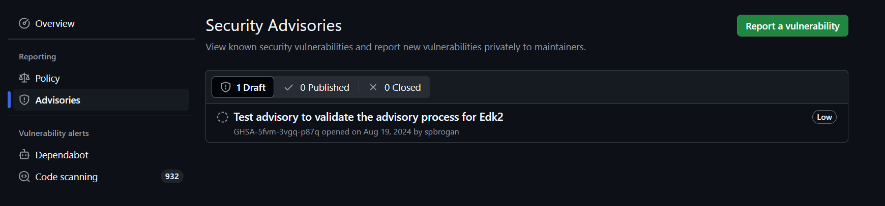
Now the Reporter can begin submitting vulnerability details.
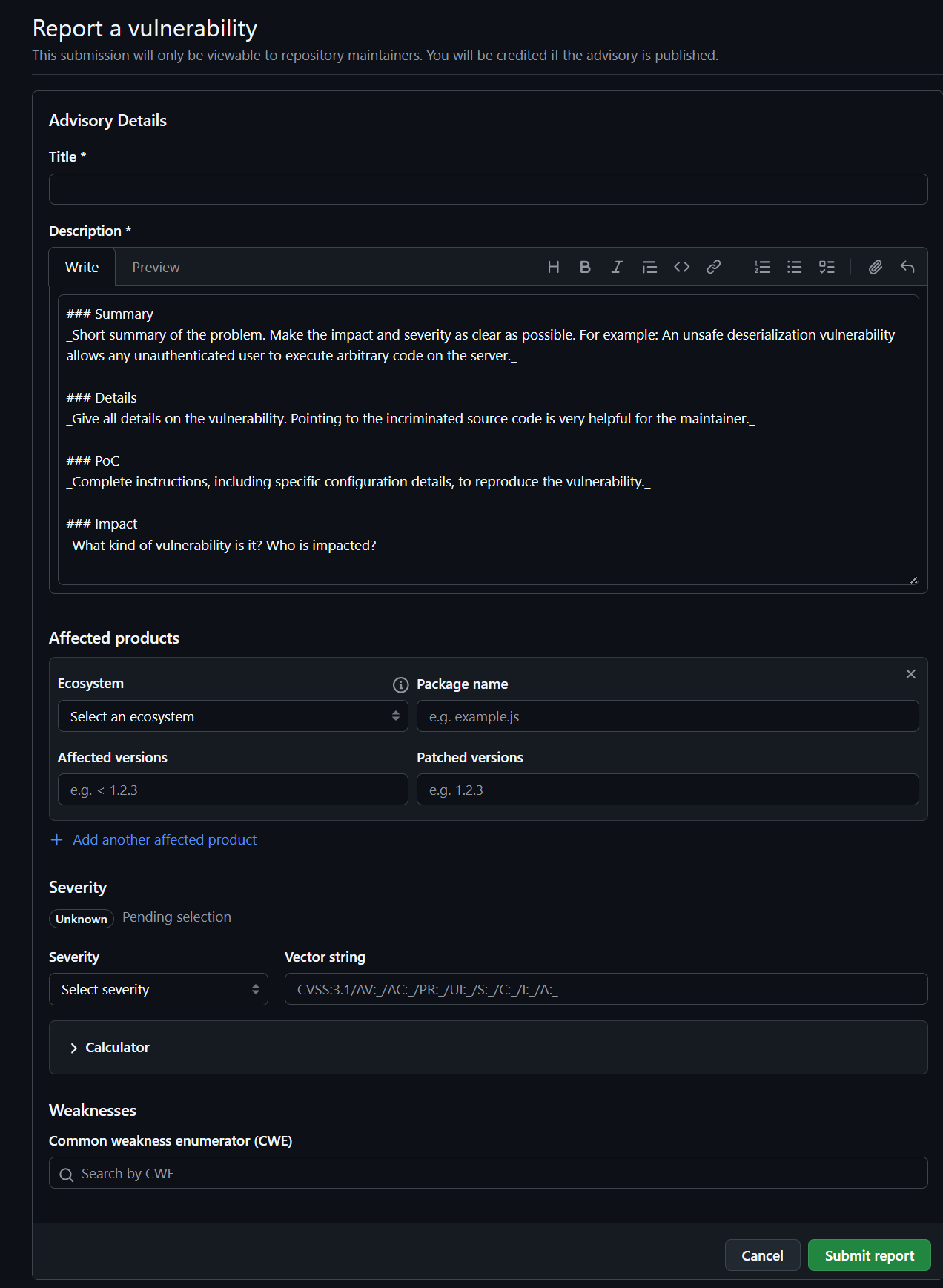
At this point the Reporter is waiting for response from the EDK2 Info Sec group.
Alternatively a report may be given by VINCE. In that case, the reporter should be directed to the github security page to submit the security issue for internal tracking.
Stage: Triage
When a new CVE is identified, a Remediation Coordinator must be designated.
The Remediation Coordinator must then find the following:
Remediation Developer- 2x
Remediation Reviewers(ideally SMEs of the patch in the Infosec community)
The Remediation Developer must find developers either within their own organization or within the Infosec community.
Once these roles are filled, the process can move on to the Fix stage.
If the submission is not found to be a CVE, the Remediation Coordinator must work with the submitter to close the
issue. The Reporter is allowed to (and probably will) write up public documentation.
Stage: Fix
During this stage, the Remediation Coordinator will inform the Reporter that the 180 day embargo has begun. The
Remediation Coordinator should provide the Reporter with up-to-date information and be the ONLY voice discussing
when patches will be available.
The Remediation Coordinator should then create a new GHSA and a temporary fork for the Advisory. Each Advisory will
have exactly one fork that may contain multiple branches, forked from EDK2.
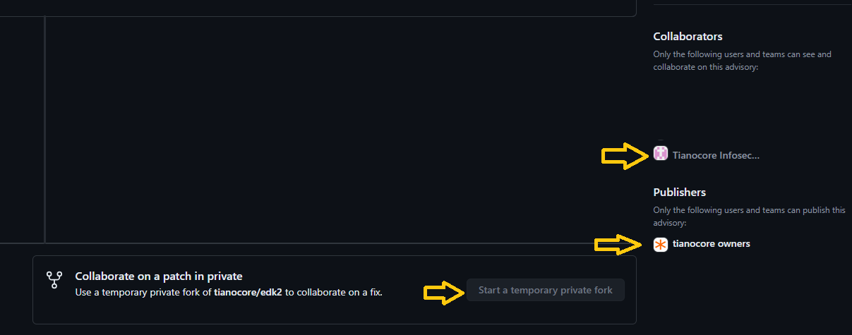
The Remediation Developer will perform their work and create a patch as soon as possible. If they have questions
they should contact the Remediation Reviewers ASAP.
The Remediation Developer must update the appropriate package security vulnerabilities
json to indicate what is being patched.
Ideally this should be completed within 90 days. Leaving another 90 days at minimum for testing across a wide range of platforms and feedback.
Stage: Review
When the Remediation Developer is ready for a review, they will create a review on the private fork targeting the
primary branch.
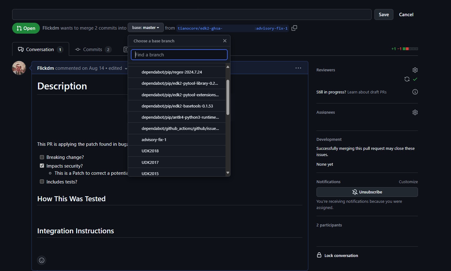
The pipelines are not expected to work. To reduce the work that will need to take place in the public, the Remediation Developer should run as many CI checks locally as they can (formatting, etc).
Example: PatchCheck, Uncrustify, etc
During this stage, the Remediation Reviewers must be responsive. If one or both reviewers are unresponsive, the
Remediation Coordinator should contact them as soon as possible. If unresponsiveness continues, the Remediation Coordinator should involve a maintainer to push the patch forward quickly.
The Remediation Coordinator should encourage the Reporter to review the patch and verify if they are able to
reproduce the original vulnerability.
The review will be considered complete when both Remediation Reviewers or maintainer have accepted the patch. If two
Remediation reviewers could not be found, then a maintainer may act as the additional or final approver.
Stage: Publish
Once the review is complete, and the team is ready to publish. The rest should follow in quick succession (1 Day)
The Remediation Coordinator must work with (or be a) Security Advisory Writer or a maintainer to create a branch
that follows the format "/security-advisory/cve-xxx-xxxx/advisory".
This special branch will not be the final destination but simply a means to publish the branch so that the community can be advised and comment. However this branch must be merged in within 24 hours.
Next, the Remediation Developer should target the new branch. Then the Remediation Developer may close their previous
reviewed PR that was targeting master.
The Security Advisory Writer or Remediation Coordination or Maintainer may merge the new branch. Then Remediation Coordinator may then publish the GHSA and credit the appropriate parties.
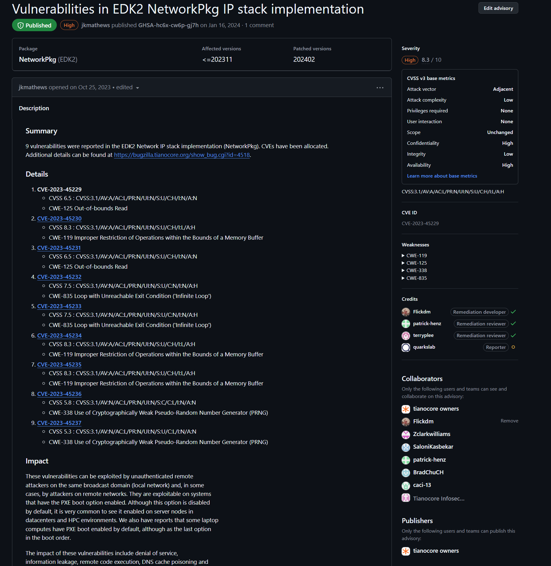
Stage: Merge
The final stage is to merge the patch into the primary branch. Here the Remediation developer will create a pull request against the primary branch. Any final CI issues should be address and the community has 24 hours to comment before being merged in.
Once merged the process is complete.
Security Advisory Process
Security Advisory Process
Now using Security reporting through the following: Reporting Security Issues
Below for archive reference only
-
IMPORTANT: All mail sent via this reflector are TianoCore Code Contributions
-
IMPORTANT: Please consider encrypting your message. We support S/MIME. If you do not have encryption available, describe the issue in generalities to establish the converstation. We can then work out some mutually agreeable method of encrypting the details in subsequent private conversations.
-
IMPORTANT: Please indicate in your initial mail if you are asking for any embargo on the information in the mail or on fixes associated with the report (ahead of a security conference, for example). We do not make assurances that all such requests will be granted.
-
Common practice in the software community when managing a security issue is:
- Receive or discover an issue.
- Rank the issue using DREAD or CVSS or ...
- If the issue is low risk, simply provide a fix via the site's non-security bug fixing methods
- Describe the issue,its vulnerabilities, and the fix to the site's trusted users
- Embargo the fix from the open site to give time for the users to review and apply the fix and provide the fixed update to their customers.
- After the embargo is complete, the complete vulnerability is described on the site.
We are aware that BIOS/Boot firmware is rarely updated by consumers or by enterprise IT departments. This makes the embargo generally impractical. It also makes the complete vulnerability description counterproductive. So, this site operates under the following modified version:
- Modified Steps:
- same as above
- same as above
- same as above
- Describe the issue, its vulernabilities, and the fix to the site's trusted users. The users have 1 week to provide comments and request an embargo.
- If reasonable rationale is provided for an embargo, the embargo occurs (as in 5 above).
- The issue is fixed in the public tree, but only the normal bug description is provided.
- A list of all issues fixed in designated files are provided via a pdf on this page.
(As noted above, the embargo in step 5 may also be requested as a part of the initial issue report.)
Designated files (step 7) are indicated by a comment in the header that the file may process untrusted input. These files are so designated because they protect the assets in the tianocore.org threat model. See (http://www.uefi.org/sites/default/files/resources/Intel-UEFI-ThreatModel.pdf) for information on the assets. If you believe other files should be so designated, please use the report button to provide the path. The "untrusted input" header comment is also used to indicate that the files so marked have had focused security reviews and may require security reviews when changes are made.
As implied in step 4 above, tianocore.org maintains a list of trusted users who receive early notification of vulnerabilities so that implementations using tianocore.org code may be upgraded and distributed prior to open notification. By joining the list, you agree to limit disclosure of any issues reported by the reflector to those necessary to fix and manage the issue. Failure to effectively manage this confidential information may result in your removal from the reflector. The list is managed by the trusted users on the list itself. Those managing the list reserve the right to limit the size and membership of the list.
EDK II Security White Papers
A list of White Papers and information for EDK II Security from multiple sources
- https://uefi.org
- https://software.intel.com/en-us/firmware/
- https://tianocore.org
- Industry standard:
- SideChannel: Intel Software Developer Zone -firmware speculative execution
- MDS: Intel Software Developer Zone - microarchitectural data sampling
General:
- Book - building secure firmware (October 2020)
- uefi.org - An Introduction to Platform Security (Spring 2018)
- uefi.org - Threat Modeling for Modern System FW.pdf (July 2013)
EDK II Code:
- A Tour Beyond BIOS - Security Design Guide in_EDK_II.pdf (Sept 2016)
- EDK II Secure Coding Guide (June 2019)
- EDK II Secure Code Review Guide (June 2019)
- OCP - Secure Firmware Development Best Practices (May 2020)
- Universal Scalable Firmware - Security (October 2021)
Memory Protection:
- A Tour Beyond BIOS – Memory Protection in UEFI BIOS - gitbook (March 2017)
- A Tour Beyond BIOS - Mitigate Buffer Overflow in UEFI (April 2018)
SMM Protection:
- A Tour Beyond BIOS Secure SMM Communication (April 2016)
- uefi.org - SMM Protection in EDK II (Spring 2017)
SecureBoot/AuthVariable:
- Understanding the UEFI Secure Boot Chain (June 2019)
- A Tour Beyond BIOS - Implementing UEFI Authenticated Variables in SMM with EDK II (Oct 2015)
TrustedBoot/TPM2:
- Understanding the Trusted Boot Chain Implementation (Nov 2020)
- A Tour Beyond BIOS - with the UEFI TPM2 Support in EDK II (Sept 2014)
- FSP2 Measurement and Attestation (July 2021)
- uefi.org - Traceable Firmware Bill of Materials Overview
DMA: A Tour Beyond BIOS - Using IOMMU for DMA Protection in UEFI firmware (Oct 2017)
Capsule/Recovery: A Tour Beyond BIOS - Capsule Update and Recovery in EDK II (Dec 2016)
S3: A Tour Beyond BIOS - Implementing S3 Resume with EDK II (Oct 2015)
Profile: A Tour Beyond BIOS - Implementing Profiling in EDK_II (July 2016)
STM/VMM:
- A Tour Beyond BIOS - Launching STM to Monitor SMM in EDK II (Aug 2015)
- A Tour Beyond BIOS - Launching a VMM in EDK II (Oct 2015)
- A Tour Beyond BIOS - Supporting SMM Resource Monitor using EDK II (June 2015)
StandaloneMM: A Tour Beyond BIOS - Launching Standalone SMM Drivers in the PEI Phase using EDK II (May 2015)
Host-Based Firmware Analyzer
Host-based Firmware Analyzer (HBFA) enables advanced testing of UEFI drivers and UEFI Platform Initialization (PI) drivers in the developer's OS environment. This test system was contributed to TianoCore edk2-staging branch by Intel in April 2019.
https://github.com/tianocore/edk2-staging/tree/HBFA
Background
Computer platform firmware is a critical element in the root-of-trust. Firmware developers need a robust tool set to analyze and test firmware components, enabling detection of security issues prior to platform integration and helping to reduce validation costs. HBFA allows developers to run open source advanced tools, such as fuzz testing, symbolic execution, and address sanitizers in a system environment.
Additional Information
- Using Host-based Analysis to Improve Firmware Resiliency (blog)
- Using Host-based Analysis to Improve Firmware Resiliency (whitepaper)
Complete Tasks
These tasks have already been completed and are examples of successful projects from prior years.
Previously Complete Projects
GSoC 2021
ext4 driver
Develop a read-only ext4 filesystem driver. http://en.wikipedia.org/wiki/Ext4
- Difficulty: Medium ... Hard
- Language: C
- Mentors: Mike Kinney (https://github.com/mdkinney) and Bret Barkelew (https://github.com/corthon)
- Suggested by: rsun3
- Status: Completed :heavy_check_mark: as GSoC2021 project by Pedro Falcato (https://github.com/heatd).
- Available at: https://github.com/tianocore/edk2-platforms/tree/master/Features/Ext4Pkg
More information: Tasks-ext2 file-system driver
Port MinPlatform to the Acer Aspire VN7-572G
Build a MinPlatform board port for the Acer Aspire VN7-572G.
- Language: C
- Mentors: Nate DeSimone (https://github.com/nate-desimone), Isaac Oram (https://github.com/iworam), and Michael Kubacki (https://github.com/makubacki)
- Suggested by: https://github.com/nate-desimone
- Status: Completed :heavy_check_mark: as GSoC2021 project by Benjamin Doron (https://github.com/benjamindoron).
- Available at: https://github.com/tianocore/edk2-platforms/tree/master/Platform/Intel/KabylakeOpenBoardPkg/AspireVn7Dash572G
More information: https://gist.github.com/benjamindoron/cf9ce28bba0b6356113918a40814af30
Formally Verified PE/COFF Loader
- Language: C
- Mentors: Bret Barkelew (https://github.com/corthon) and Benjamin You (https://github.com/BenjaminYou)
- Suggested by: https://github.com/mhaeuser
- Status: Completed :heavy_check_mark: as GSoC2021 project by Marvin Häuser (https://github.com/mhaeuser).
More information: https://github.com/mhaeuser/gsoc-2021-edk2-pe-loader
Enable Clang/LLVM Build for Microsoft Windows
https://llvm.org/ support in EDK II is currently limited to Linux builds. Getting LLVM running on Windows would enable the TianoCore project to support Clang and the LLVM toolchain more robustly. Microsoft Windows 10 should be the primary target.
- Difficulty: Medium
- Language: C, Python
- Mentor: https://github.com/shijunjing
- Suggested by: https://github.com/shijunjing
- Status: Completed :heavy_check_mark: as GSoC2021 project by Yuqi Chen (https://github.com/alyssachne).
- Available at: https://github.com/tianocore/edk2-staging/tree/2021-gsoc-llvm-gnumake
Terminal driver improvements
Optimize cursor motion sequences; support Linux/UNIX standard (xterm/konsole/gnome-terminal/etc.) key codes and line-drawing characters (currently one must set their terminal emulator to use code page 437 for correct line drawing.)
- Difficulty: Medium
- Language: C
- Mentor: https://github.com/nate-desimone and Rocio Hernandez Fabian
- Suggested by: bjjohnson, https://github.com/nate-desimone
- Status: Completed :heavy_check_mark: as GSoC2021 project by Caden Kline (https://github.com/Pokemod97).
- Available at: https://github.com/Pokemod97/edk2/tree/terminal-driver-characters-v3
More information: Tasks-Terminal-driver-improvements
GSoC 2012
USB-to-serial driver
Develop a USB driver for a common USB-to-serial adapter.
- Difficulty: Medium
- Language: C
- Mentor: https://github.com/ErikBjorge
- Suggested by: https://github.com/jljusten
- Status: Completed :heavy_check_mark: as a GSoC2012 project by Ashley DeSimone (https://github.com/ashedesimone).
- Available at https://github.com/tianocore/edk2-platforms/tree/master/Drivers/OptionRomPkg/Bus/Usb/FtdiUsbSerialDxe
More information: Tasks-USB Serial Adapter driver
GSoC 2011
Read-only FFS file-system driver
Develop a read-only filesystem driver which allows the contents of each PI 1.2 FFS in the system to appear as a pseudo-file system.
- Difficulty: Medium
- Language: C
- Mentor:
- Suggested by: https://github.com/mdkinney
- Status: Completed :heavy_check_mark: as a GSOC2011 project by Colin Drake (https://github.com/cfdrake).
- Available at: https://github.com/tianocore/edk2/tree/master/MdeModulePkg/Universal/FvSimpleFileSystemDxe
More information:
Other Completed Projects
Shell editor improvements
Various improvements for the Shell editor
- Difficulty: Medium
- Language: C
- Mentor: https://github.com/jljusten
- Suggested by: https://github.com/jljusten, https://github.com/ErikBjorge, https://github.com/jcarsey
- Status: Available in main edk2 tree
More information: Tasks-Text Editor
Optimize OVMF for Xen HVM domains
Add Xen specific support in OVMF to improve boot & runtime performance. http://www.xen.org/
- Difficulty: Medium/Hard
- Language: C
- Mentor:
- Suggested by: andreiwarkentin, Bei Guan
- Status: Implemented via https://github.com/tianocore/edk2/issues/7876
Port EmulatorPkg to Windows
Port EmulatorPkg to Microsoft Windows (32/64 bit), as a replacement for NT32.
- Difficulty: Medium
- Language: C
- Mentor:
- Suggested by: https://github.com/ajfish
More information: Tasks-EmulatorPkg for Windows
Add Visual Studio 2017 Support
Microsoft Visual Studio will be released March 7, 2017. Add VS2017 build support to EDK II.
Port Intel Firmware Engine SDK Extensions to OVMF
Intel Firmware Engine adds UserExtensions in the SDK to describe connections between modules and module parameters (as "Patchable In Binary" PCDs). This enables binary distribution of configurable firmware components. Porting these extensions to a branch of OVMF would allow development and testing of these concepts on a virtual platform.
- Status: This application has EOL'd as of Aug 2019
- Languages: C, Python
- Mentor: https://github.com/jcarsey
Enable Xen Support in OVMF
Get Xen to boot UEFI with OVMF.
- Difficulty: Hard (depending on tasks taken on)
- Language: C
- Mentor: andreiwarkentin, https://github.com/jljusten
- Suggested by: andreiwarkentin
- Status: Available in main edk2 tree
Multiprocessor support in UefiCpuPkg/CpuDxe
Enable multiprocessor support for IA32 & X64 within UefiCpuPkg/CpuDxe. (Implement MdePkg/Include/Protocol/MpService.h)
- Difficulty: Medium
- Language: Assembly, C
- Mentor:
- Suggested by: https://github.com/jljusten
- Status: Available in EDK II tree
More information: Tasks-UefiCpuPkg-CpuDxe MP support
Enable Link-time Code Optimization for Linux builds
Enable Link-time Code Optimization on Linux for either GCC or LLVM/CLANG. http://gcc.gnu.org/wiki/LinkTimeOptimization
This feature hopefully would significantly reduce code generation size for Linux based builds.
- Difficulty: Medium
- Language: C
- Mentor:
- Suggested by: https://github.com/ajfish, https://github.com/jljusten
- Status: Available in GCC5 & CLANG38 toolchains
See Also
UDK2010.SR1 How To Build
Build Instructions
Download the UDK2010.SR1 Release with expanded workspace directories Download
UDK2010.SR1 Release Files / Directories
What is included in the Downloaded zip file
- UDK2010.SR1.MyWorkSpace.zip
- BaseTools(Windows)_UDK2010.SR1.zip
- BaseTools(Unix)_UDK2010.SR1.tar
- Documents
- Notes
Windows System Configuration
Microsoft Windows 7 Ultimate 64-bit*
1. Setup Build Environment
- 1) Install Microsoft Visual Studio 2008* SP1 in the build machine and make sure that AMD64 complier was selected when installing.
- 2) Download "iasl-win-20070508.zip" from "http://www.acpica.org/downloads/Version_20070508.php" and extract file "iasl.exe" to C:\ASL
2. Extract Common Source Code
- 1) Extract files in [UDK2010.SR1.MyWorkSpace.zip] to the working space directory (e.g C:). Note the Directory "MyWorkSpace" will be created as a result. In this case, it is C:\MyWorkspace.
- 2) There are two BaseTools package one is for Windows system and another is for UNIX-Like system. Please make sure BaseTools(Windows)_UDK2010.SR1.zip is used here. Expand the appropriate BaseTools to C:\MyWorkSpace
3. Generate OpenSSL* Crypto Library Note: this does not need to be done for Nt32
- Open file "C:\MyWorkspace\CryptoPkg\Library\OpensslLib\Patch-HOWTO.txt" and follow the instruction to install OpenSSL* for UEFI building.
4. Build Steps *** NT32 ***
- 1) Open a command prompt, type command "cd C:\MyWorkspace" to enter the workspace directory, and then type command
> edksetup
to initialize the working environment. See also:
Windows systems ToolChain Matrix
for supported compiler combinations when updating TOOL_CHAIN_TAG.
- 2) Type below commands to build platforms
> build -t VS2008x86
Note: There are two methods to select the tool chain (Use Microsoft Visual Studio 2008* as sample):
- 1. Update TOOL_CHAIN_TAG in file Conf/target.txt: TOOL_CHAIN_TAG = VS2008
- 2. Add -t build option in command line: "build -t VS2008 ... "
For 32-bit VS2008 on 64-bit WINDOWS OS, VS2008x86 should be selected instead of VS2008. Please refer to tools_def.txt for all supported tool chains and detailed descriptions. (tools_def.txt will be generated at Conf directory after running "edksetup".)
Unix-Like System Configuration
Ubuntu
DistributorID: Ubuntu*
Description: Ubuntu 10*
Release: Ubuntu 10.10*
Codename: Karmic*
1. Extract Common Source Code
- 1) Create a working space directory in the build machine, for example, ~/src/
- 2) Extract files in [UDK2010.SR1.MyWorkSpace.zip] the working space directory. In this case, it is ~/src/MyWorkSpace where /MyWorkSpace is created.
- 3) There are two BaseTools packages, one is for Windows system and another is for UNIX-Like system. Please make sure BaseTools(Unix)_UDK2010.SR1.tar is used here.
2. Generate OpenSSL* Crypto Library Note: This does not need to be done for Nt32 Open file "~/src/MyWorkspace/CryptoPkg/Library/OpensslLib/Patch-HOWTO.txt" and follow the instruction to install OpenSSL* for UEFI building.
3. See How to Set up Build environment Using EDK II with Native GCC for newer versions of Linux
- a) Please note that here the root is "
/src/MyWorkSpace" instead of "/src/edk2" - b) Make sure BaseTools is built and required software like iASL compiler is installed well.
- c) Some operations need switch to user "root" to execute.
4. Build Steps *** Nt32 ***
- 1) Open a terminal and type "cd ~/src/MyWorkSpace" to enter the workspace directory.
- 2) Initialize the build environment by typing
>. edksetup.sh BaseTools
- 3) Type below commands to build platforms
> build -t GCC44
UDK2010.SR1.Up1 How To Build
Build Instructions
Download the UDK2010.SR1.UP1.P1 Release with expanded workspace directories Download
UDK2010.SR1.UP1.P1 Release Files / Directories
What is included in the Downloaded zip file
- UDK2010.SR1.UP1.P1.MyWorkSpace.zip
- BaseTools(Windows).zip
- BaseTools(Unix).tar
- Documents
Windows System Configuration
Microsoft Windows 7 Ultimate 64-bit*
1. Setup Build Environment
- 1) Install Microsoft Visual Studio 2008* SP1 in the build machine and make sure that AMD64 complier was selected when installing.
2. Extract Common Source Code
- 1) Extract files in [UDK2010.SR1.MyWorkSpace.zip] to the working space directory (e.g C:). Note the Directory "MyWorkSpace" will be created as a result. In this case, it is C:\MyWorkspace.
- 2) There are two BaseTools package one is for Windows system and another is for UNIX-Like system. Please make sure BaseTools(Windows)_UDK2010.SR1.zip is used here. Expand the appropriate BaseTools to C:\MyWorkSpace
3. Generate OpenSSL* Crypto Library Note: this does not need to be done for Nt32
- Open file "C:\MyWorkspace\CryptoPkg\Library\OpensslLib\Patch-HOWTO.txt" and follow the instruction to install OpenSSL* for UEFI building.
4. Build Steps *** NT32 ***
- 1) Open a command prompt, type command "cd C:\MyWorkspace" to enter the workspace directory, and then type command
> edksetup --nt32
to initialize the working environment. See also: Windows systems ToolChain Matrix for how to change the TOOL_CHAIN_TAG for supported compiler combinations.
- 2) Type below commands to build platforms (below assumes Microsoft Visual Studio 2008)
> build -t VS2008x86
Note: There are two methods to select the tool chain (Use Microsoft Visual Studio 2008* as sample):
- 1. Update TOOL_CHAIN_TAG in file Conf/target.txt: TOOL_CHAIN_TAG = VS2008
- 2. Add -t build option in command line: "build -t VS2008 ... "
For 32-bit VS2008 on 64-bit WINDOWS OS, VS2008x86 should be selected instead of VS2008. Please refer to tools_def.txt for all supported tool chains and detailed descriptions. (tools_def.txt will be generated at Conf directory after running "edksetup".)
- 3. Note Microsoft Visual Studio* 2010 is supported with -t VS2010 or -t VS2010x86
Unix-Like System Configuration
Ubuntu
DistributorID: Ubuntu*
Description: Ubuntu 10*
Release: Ubuntu 10.10*
Codename: Karmic*
1. Extract Common Source Code
- 1) Create a working space directory in the build machine, for example, ~/src/
- 2) Extract files in [UDK2010.SR1.MyWorkSpace.zip] the working space directory. In this case, it is ~/src/MyWorkSpace where /MyWorkSpace is created.
- 3) There are two BaseTools packages, one is for Windows system and another is for UNIX-Like system. Please make sure BaseTools(Unix)_UDK2010.SR1.tar is used here.
2. Generate OpenSSL* Crypto Library Note: This does not need to be done for Nt32 Open file "~/src/MyWorkspace/CryptoPkg/Library/OpensslLib/Patch-HOWTO.txt" and follow the instruction to install OpenSSL* for UEFI building.
3. See How to Set up Build environment Using EDK II with Native GCC for newer versions of Linux
- a) Please note that here the root is "
/src/MyWorkSpace" instead of "/src/edk2" - b) Make sure BaseTools is built and required software like iASL compiler is installed well.
- c) Some operations need switch to user "root" to execute.
4. Build Steps *** Nt32 ***
- 1) Open a terminal and type "cd ~/src/MyWorkSpace" to enter the workspace directory.
- 2) Initialize the build environment by typing
>. edksetup.sh BaseTools
- 3) Type below commands to build platforms
> build -t GCC44
UDK2014 - How To Build
Build Instructions
Download the UDK2014 Release with expanded workspace directories DownLoad
UDK2014 Release Files / Directories
What is included in the Downloaded zip file
- UDK2014.MyWorkSpace.zip
- BaseTools(Windows).zip
- BaseTools(Unix).tar
- Documents
- Notes
Windows System Configuration
Microsoft Windows 7 Ultimate 64-bit*
1. Setup Build Environment
- 1) Install Microsoft Visual Studio 2008* SP1 in the build machine and make sure that AMD64 complier was selected when installing.
2. Extract Common Source Code
- 1) Extract files in [UDK2014.MyWorkSpace.zip] to the working space directory (e.g C:). Note the Directory "MyWorkSpace" will be created as a result. In this case, it is C:\MyWorkspace.
- 2) There are two BaseTools package one is for Windows system and another is for UNIX-Like system. Please make sure BaseTools(Windows).zip is used here. Expand the appropriate BaseTools to C:\MyWorkSpace
3. Generate OpenSSL* Crypto Library Note: this does not need to be done for Nt32
- Open file "C:\MyWorkspace\CryptoPkg\Library\OpensslLib\Patch-HOWTO.txt" and follow the instruction to install OpenSSL* for UEFI building.
4. Build Steps *** NT32 ***
- 1) Open a command prompt, type command "cd C:\MyWorkspace" to enter the workspace directory, and then type command
> edksetup --nt32
to initialize the working environment. See also: Windows systems ToolChain Matrix for how to change the TOOL_CHAIN_TAG for supported compiler combinations.
- 2) Type below commands to build platforms (below assumes Microsoft Visual Studio 2008)
> build -t VS2008x86
Note: There are two methods to select the tool chain (Use Microsoft Visual Studio 2008* as sample):
- 1. Update TOOL_CHAIN_TAG in file Conf/target.txt: TOOL_CHAIN_TAG = VS2008
- 2. Add -t build option in command line: "build -t VS2008 ... "
For 32-bit VS2008 on 64-bit WINDOWS OS, VS2008x86 should be selected instead of VS2008. Please refer to tools_def.txt for all supported tool chains and detailed descriptions. (tools_def.txt will be generated at Conf directory after running "edksetup".)
- 3. Note Microsoft Visual Studio* 2010 is supported with -t VS2010 or -t VS2010x86
Unix-Like System Configuration
Ubuntu
DistributorID: Ubuntu*
Description: Ubuntu 10*
Release: Ubuntu 10.10*
Codename: Karmic*
1. Extract Common Source Code
example, ~/src/ directory. In this case, it is ~/src/MyWorkSpace where /MyWorkSpace is created. another is for UNIX-Like system. Please make sure BaseTools(Unix).tar is used here.
2. Generate OpenSSL* Crypto Library Note: This does not need to be done for Nt32 Open file "~/src/MyWorkspace/CryptoPkg/Library/OpensslLib/Patch-HOWTO.txt" and follow the instruction to install OpenSSL* for UEFI building.
3. See How to Set up Build environment Using EDK II with Native GCC for newer versions of Linux
"~/src/edk2" compiler is installed well.
4. Build Steps *** Nt32 ***
workspace directory.
>. edksetup.sh BaseTools
> build -t GCC44
How to Build UDK2017
New build instructions are available. It is recommended to start with the new instructions if learning how to build edk2 for the first time and not specifically targeting UDK2017. This page is retained for reference.
New instructions: Build Instructions
Table of Contents
HOW TO BUILD (WINDOWS SYSTEM)
The steps below are verified on Microsoft Windows 10 Enterprise*:
-
Setup Build Environment
- Install Microsoft Visual Studio 2015* in the build machine and make sure that AMD64 complier was selected when installing.
- Download NASM 2.0.7 or later from http://www.nasm.us/ and install it to C:\Nasm. Make sure C:\Nasm is added to system environment variable 'PATH'
- Set up for using GitHub for Windows. See: ../../../development/tutorials-howto/getting_started_with_edk_ii.md#github-help
- Download and install Python2.7.x https://www.python.org/ for building the BaseTools Default install directory is: C:/Python27
-
Create the full Source Code directory for the UDK2017 release
- Create a working space directory in the build machine, for example, C:\MyWorkspace
- Download the official UDK2017 release .zip file from the UDK2017 Release
Page
- Download - UDK2017 edk-vUDK2017 Workspace Source code (zip file)
- Extract files in
edk2-vUDK2017to the working space directory C:\MyWorkspace.
- OR Checkout the vUDK2017 Tag from GitHub with the following "git" command
- run
git clone https://github.com/tianocore/edk2.git vUDK2017 - Move all files and folders under "vUDK2017" to "C:\MyWorkspace"
- run
- Optional (See Compile the BaseTools below) Checkout BaseTools binaries and copy them to BaseTools binary
folder. Warning the Windows* Binary tools are only valid for the tip of the
https://github.com/tianocore/edk2 repository.
Cd C:\MyWorkspace- Run
git clone https://github.com/tianocore/edk2-BaseTools-win32.git - Enter folder edk2-BaseTools-win32
- Run the command
git checkout 0e088c19ab31fccd1d2f55d9e4fe0314b57c0097 Cd C:\MyWorkSpace- Rename this folder from edk2-BaseTools-win32 to win32, then copy the win32 directory into the BaseTools/Bin directory under the workspace. (e.g. "C:\MyWorkspace\BaseTools\Bin")
-
Generate OpenSSL* Crypto Library
- Open file "C:\MyWorkspace\CryptoPkg\Library\OpensslLib\OpenSSL-HOWTO.txt" and follow the instruction to install OpenSSL* for UEFI building. For this release, please use OpenSSL-1.1.0e.
-
Compile the BaseTools (Skip if Optional Step 2.iv was done above) See: ../../../build-tooling/environment-setup/windows_systems.md#compile-tools
- Open a Microsoft Visual Studio* command prompt, type
cd C:\MyWorkspaceto enter the workspace directory - Compile the BaseTools C source tools
set PYTHON_HOME=C:\Python27 set EDK_TOOLS_PATH=%CD%\BaseTools BaseTools\toolssetup.bat Rebuild - Open a Microsoft Visual Studio* command prompt, type
-
Build Steps
NT32
- Open a Microsoft Visual Studio* command prompt, type
cd C:\MyWorkspaceto enter the workspace directory - Use edksetup.bat command to initialize the working environment.
edksetup --nt32 - Type following command to build Nt32 platform
build -t VS2015x86 - Upon the build completing successfully there should be the UEFI Application "
HelloWorld.efi" in the C:\MyWorkspace\Build\MdeModule\DEBUG_VS2015x86\IA32 directory
- Open a Microsoft Visual Studio* command prompt, type
HOW TO BUILD (LINUX-LIKE SYSTEM)
The below steps are verified on Ubuntu 16.04 LTS Desktop*:
-
Setup Build Environment
- Follow instructions for setting up the build environment on tianocore.org. "Using EDK II with Native GCC"
- Please notice that here the root is
"~/src/MyWorkspace"instead of"~/src/edk2" - Make sure BaseTools is built and required software like iASL compiler
are installed. Some operations need switch to user "root" to execute.
At Ubuntu, you can type
"sudo apt-get install git"under terminal prompt "Cnt-Alt-T" to install git. - Install NASM 2.0.7 or later.
At Ubuntu, you can type
"sudo apt-get install nasm"under terminal prompt to install it. You can also download the source package from http://www.nasm.us/ and install it following the instruction on the website. - Install IASL 20150818 or later.
At Ubuntu, you can type
"sudo apt-get install iasl"under terminal prompt to install it. You can also download the source package from https://acpica.org/downloads and install it following the instruction on the website. - Install the C Compiler- Ubuntu 16.04 LTS you can use GNU C compiler (v5.4.0)
At Ubuntu, you can type
"sudo apt-get install gcc-5"under terminal prompt to install it.
-
Create the full Source Code directory for the UDK2017 release
- Create a working space directory in the build machine, for example, ~/src/MyWorkspace
- Download the official UDK2017 release .tar file from the UDK2017 Release
Page
- Download - UDK2017 edk-vUDK2017 Workspace Source code (tar.gz file)
- Extract files in
edk2-vUDK2017to the working space directory ~/src/MyWorkspace.
- OR Checkout the vUDK2017 tag from GitHub with the following "git" command
- Run
"git clone https://github.com/tianocore/edk2.git vUDK2017" - Move all files and folders under "vUDK2017" to "~/src/MyWorkspace"
- Run
-
Generate OpenSSL* Crypto Library
- Open file "~/src/MyWorkspace/CryptoPkg/Library/OpensslLib/OpenSSL-HOWTO.txt" and follow the instruction to install OpenSSL* for UEFI building. For this release, please use OpenSSL-1.1.0e.
-
Build Steps
MdeModulePkg
- Open a terminal and type
"cd ~/src/MyWorkspace"to enter the workspace directory. - First build the BaseTools by typing
"make -C BaseTools" - Initialize the build environment by typing
". edksetup.sh". - Type following command to build platforms using GCC v5.4.0
"build -p MdeModulePkg/MdeModulePkg.dsc -t GCC5" - Upon the build completing successfully there should be the UEFI Application "
HelloWorld.efi" in the ~/src/MyWorkspace/Build/MdeModule/DEBUG_GCC5/IA32 directory
- Open a terminal and type
If you have questions please email the edk2-devel mail list.
See also Getting Started with EDK II
How to Build UDK2018
New build instructions are available. It is recommended to start with the new instructions if learning how to build edk2 for the first time and not specifically targeting UDK2018. This page is retained for reference.
New instructions: Build Instructions
Table of Contents
HOW TO BUILD (WINDOWS SYSTEM)
The steps below are verified on Microsoft Windows 10 Enterprise*:
-
Setup Build Environment
- Install Microsoft Visual Studio 2015* in the build machine and make sure that AMD64 complier was selected when installing.
- Download NASM 2.12.01 or later from http://www.nasm.us/ and install it to C:\Nasm. Make sure C:\Nasm is added to system environment variable 'PATH'
- Set up for using GitHub for Windows. See: ../../../development/tutorials-howto/getting_started_with_edk_ii.md#github-help
- Download and install Python2.7.x https://www.python.org/ for building the BaseTools Default install directory is: C:/Python27
- Download the pre-compiled Openssl binary from https://wiki.openssl.org/index.php/Binaries. Search for a Windows binary in the list of "Third Party OpenSSL Related Binary Distributions" table that will be Windows binary. Go to the third party site to download the latest version of Windows x64 86 or Win32 binary. Download and extract to C:\Openssl. Make sure C:\Openssl is added to system environment variable 'PATH'.
-
Create the full Source Code directory for the UDK2018 release
- Create a working space directory in the build machine, for example, C:\MyWorkspace
- Download the official UDK2018 release .zip file from the UDK2018 Release Page
- Download - UDK2018 edk-vUDK2018 Workspace Source code (zip file)
- Extract files in
edk2-vUDK2018to the working space directory C:\MyWorkspace. - OR Checkout the vUDK2018 Tag from GitHub with the following "git" command
- run
git clone https://github.com/tianocore/edk2.git vUDK2018 - Go to the vUDK2018 directory, and from there run:
git checkout tags/vUDK2018 -b vUDK2018 - Move all files and folders under "vUDK2018" to "C:\MyWorkspace"
- run
-
Generate OpenSSL* Crypto Library
- Open file "C:\MyWorkspace\CryptoPkg\Library\OpensslLib\OpenSSL-HOWTO.txt" and follow the instruction to install OpenSSL* for UEFI building. For this release, please use OpenSSL-1.1.0g. Download it from https://github.com/openssl/openssl/archive/OpenSSL_1_1_0g.zip Extract it to C:\MyWorkspace\CryptoPkg\Library\OpensslLib, and rename its directory name to openssl
-
Compile the BaseTools See: ../../../build-tooling/environment-setup/windows_systems.md#compile-tools
- Open a Microsoft Visual Studio* command prompt, type
cd C:\MyWorkspaceto enter the workspace directory - Compile the BaseTools C source tools
set PYTHON_HOME=C:\Python27 edksetup.bat Rebuild - Open a Microsoft Visual Studio* command prompt, type
-
Build Steps NT32
- Open a Microsoft Visual Studio* command prompt, type
cd C:\MyWorkspaceto enter the workspace directory - Use edksetup.bat command to initialize the working environment.
edksetup --nt32 - Type following command to build Nt32 platform
build -t VS2015x86 - Upon the build completing successfully there should be the UEFI Application "
HelloWorld.efi" in the C:\MyWorkspace\Build\NT32IA32\DEBUG_VS2015x86\IA32 directory
- Open a Microsoft Visual Studio* command prompt, type
HOW TO BUILD (LINUX-LIKE SYSTEM)
The below steps are verified on Ubuntu 16.04 LTS Desktop*:
-
Setup Build Environment
-
Follow instructions for setting up the build environment on tianocore.org. "Using EDK II with Native GCC"
-
Please notice that here the root is
"~/src/MyWorkspace" instead of"~/src/edk2" -
Make sure BaseTools is built and required software like iASL compiler is installed well.
- Some operations need switch to user "root" to execute.
- At Ubuntu, you can type
"sudo apt-get install git"under terminal "Cnt-Alt-T" to install git.
-
-
Install NASM 2.12.01 or later. At Ubuntu, you can type "sudo apt-get install nasm" under terminal to install it. You can also download the source package from http://www.nasm.us/ and install it following the instruction on the website.
-
Install IASL 20150818 or later. At Ubuntu, you can type
"sudo apt-get install iasl"under terminal to install it. You can also download the source package from https://acpica.org/downloads and install it following the instruction on the website.
-
-
Create the full Source Code directory for the UDK2018 release
- Create a working space directory in the build machine, for example, ~/src/MyWorkspace
- Download the official UDK2018 release .tar file from the UDK2018 Release
Page
- Download - UDK2018 edk-vUDK2018 Workspace Source code (tar.gz file)
- Extract files in
edk2-vUDK2018to the working space directory ~/src/MyWorkspace.
- OR Checkout the vUDK2018 tag from GitHub with the following "git" command
- Run
"git clone https://github.com/tianocore/edk2.git vUDK2018" - Go to the vUDK2018 directory, and from there run:
git checkout tags/vUDK2018 -b vUDK2018 - Move all files and folders under "vUDK2018" to "~/src/MyWorkspace"
- Run
-
Generate OpenSSL* Crypto Library
- Open file "~/src/MyWorkspace/CryptoPkg/Library/OpensslLib/OpenSSL-HOWTO.txt" and follow the instruction to install OpenSSL* for UEFI building. For this release, please use OpenSSL-1.1.0g. Download it from https://github.com/openssl/openssl/archive/OpenSSL_1_1_0g.zip Extract it to ~/src/MyWorkspace/CryptoPkg/Library/OpensslLib, and rename its directory name to openssl
-
Build Steps MdeModulePkg
- Open a terminal and type
"cd ~/src/MyWorkspace"to enter the workspace directory. - First build the BaseTools by typing
"make -C BaseTools" - Initialize the build environment by typing
". edksetup.sh". - Type following command to build platforms using GCC v5.4.0
"build -p MdeModulePkg/MdeModulePkg.dsc -t GCC5" - Upon the build completing successfully there should be the UEFI Application "
HelloWorld.efi" in the ~/src/MyWorkspace/Build/MdeModule/DEBUG_GCC5/IA32 directory
- Open a terminal and type
If you have questions please email the edk2-devel mail list.
See also Getting Started with EDK II
Obsolete Tasks
:red_circle: It is not recommended that anyone work on these tasks. :red_circle:
These are tasks had been previously identified by our community but for various reasons are no longer relevant and are largely historical. We do not plan to accept any GSoC proposals for these projects. Please let us know on https://edk2.groups.io/g/devel if you plan to work on one of these tasks anyway (to prevent duplicated effort).#
Build a C compiler for EBC
:red_circle: Low priority because EBC is no longer required by the UEFI spec. :red_circle:
Build a C compiler that is able to generate EBC (EFI Byte Code).
- Difficulty: Hard
- Language: C, Assembly
- Mentor:
- Suggested by: https://github.com/nate-desimone
More information: Tasks-Build-a-C-compiler-for-EBC
Compatibility Support Module
:red_circle: Low priority because TianoCore does not promote legacy boot architectures. :red_circle:
A CSM allows a UEFI system to boot legacy operating systems on IA32 & X64 systems. In other words, most current production OS's. Strong preference is for a BSD licensed solution, as this is license used by nearly all of our code. A SeaBIOS based solution could be considered, but would not be as widely usable (GPL license). http://www.coreboot.org/SeaBIOS
- Difficulty: Hard
- Language: Assembly, C
- Mentor:
- Suggested by: bjjohnson
- Status: No longer a priority, since UEFI OS support is mainstream. SeaBIOS can be built as a CSM, but a BSD licensed alternative is still not available.
Intel Galileo Platform Improvements
:red_circle: Low priority because Galileo is no longer manufactured. :red_circle:
Add features to Galileo based on open source platform in EDK II. https://github.com/tianocore/edk2/tree/master/QuarkPlatformPkg
- Switch from private SD/MMC stack to standard one in MdeModulePkg.
- Debugger/Console using USB client mode for multiple high perf UARTs in ESRAM
- Logging and Debugger support over USB using ESRAM for DMA.
Mentor: https://github.com/mdkinney
Coverity Static Analysis Tools
:red_circle: Low priority for now because one-off Coverity scans have been done and those bugs still need to be fixed. :red_circle:
Enable Coverity Scan for all EDK II projects. https://scan.coverity.com/
- Evaluate open source CI tools to fine best one to periodically auto run Coverity static analysis
- Look into ways to auto-post results to TianoCore (website, wiki, or git repo).
- Look into ways to automate GitHub issue generation based on Coverity results.
Mentor: https://github.com/mdkinney, https://github.com/shijunjing
See Also
EdkCompatibilityPkg
EdkCompatibilityPkg provides header files and libraries that enable you to build the EDK module in UEFI 2.0 + Framework 0.9x mode. This package also provides Thunk modules that enable Framework 0.9x modules to work with UEFI 2.3.1 / PI 1.2 EDK II Platforms.
EDK FAT Driver
fat-driver Project home http://sourceforge.net/projects/edk-fat-driver/
Please read the news on the home page regarding the SITE TRANSITION—DOWNTIME January 21. Very important information regarding coming changes.
Request project membership/role | Watch project Summary Project for the Fat32 Driver Category sample-driver License Other Owner(s)
Welcome to the FAT-Driver PROJECT, a project for the FAT32 File System Driver, which is based on Microsoft's FAT32 File System Driver Specification. The Fat Driver is separate from the EDK project only because the terms of use of the code are unique, requiring us to keep it in a separate code repository (the terms are basically that code developed using the FAT32 Specification must be associated with EFI).
This project is a subproject of the EDK project, and is only used to house the FAT32 code respository. All development tools in the EDK project are integrated with this project, so come here only to update the CVS repository or to get access to the latest code snapshots. Use the EDK project to post issues, join mailing lists, participate in discussion forums, etc. In short, consider them one project with two code repositories. FAT-Driver News
The FAT-Driver development team is pleased to announce a new "Enhanced" FAT-Driver. This project will now be used to develop and maintain both drivers. From this point on, the original FAT-Driver will be refererred to as FAT-Driver while the new driver will go by the Enhanced-FAT-Driver name. Both drivers will be using the same Project Tracer and each have their own module name when creating/modifying TASKs or ENHANCEMENTs. The enhanced-fat-driver is also published under the same license as the fat-driver. To view more specific information about the enhanced-fat-driver, go to the Enhanced-FAT-Driver section. Working with the FAT32 Code
The FAT-Driver project is sponsored by Intel and released under the BSD license with one additional term. Before using the code please read the license below, paying special attention to the "Additional Terms" section:
To download code, view the directory of code snapshots and choose the version (Official Release or Development Version) you are interested in and simply click on it to start the download process. Join this project if you want to contribute code changes (see the next section for guidance). Enhanced-FAT-Driver
The Enhanced-FAT-Driver is a new implementation of the FAT32 filesystem. It is a near complete rewrite of the original FAT-Driver with over 80% of the code being specific just to the Enhanced-FAT-Driver. The new driver is faster and takes up only 66% of the original FAT-Driver's memory footprint. What makes the Enhanced-FAT-Driver better?
* Better Architecture
o More modular design thanks to object oriented and hierarchical design
o Logic directory approach used in place of the physical directory
o Easier to maintain and debug
o 80% of the code was completely rewritten to make it smaller and faster
* Higher Performance
o A cache mechanism to cache recently opened directories
o A more efficient 8.3 name generation algorithm
o 10x, 100x or even 1000x acceleration when creating thousands files/directories
* Smaller Size
o Simplified the controller name from "FAT File System[FAT16] 200MB" to "FAT File System"
o Succinct coding style
o 2/3 the image size of the original FAT-Driver
So why are there two FAT-Driver implementations in the fat-driver project?
* Publish the enhanced FAT implementation so that people can try the new implementation with size and performance benefits
* Keep the original FAT driver for backward compatibility or avoid potential risk for mature products
Which driver should I use?
* Enhanced-FAT-Driver
o When you need the fastest FAT filesystem driver
o When space is crucial
* FAT-Driver
o When you need stability to avoid possible risk of a new implementation
o When you prefer to keep the original behavior, such as 8.3 name generation algorithm, complete controller name fnor each volume`
What does this mean to you?
Not much. The source code will be housed in the same repository so there is no need to checkout multiple projects to work on these drivers. The Project Tracker configuration is setup to allow for concurrent DEFECT, ENHANCEMENT and TASK management for both projects. The only real concern for you is to figure out which driver to use when. Joining the FAT-Driver Project
To join the FAT-Driver Project simply click on the "Request Project Membership/Role" link above and choose "Observer" as a requested role (that's the default role for all new project members). Upon receipt of your request, the FAT-Driver Maintainer will approve your project membership. Once in the project you'll primarily use the CVS repository located here, or access the FAT32-specific documents located here. Managing Changes to the FAT-Driver Source Code
Since the FAT32 Driver Code is actually part of the EDK, changes to it are managed within the EDK issue management system. To make it simple for you, the following links have been developed to help the communication between the two projects. From these links you can enter a FAT32 issue, query open FAT32 issues, access the DEV mailing list archive and download the FAT32 source code.
* Enhanced FAT-Driver
o Latest Enhanced-FAT-Driver Source Code Snapshot (Development Version)
o Latest Enhanced-FAT-Driver Source Code Snapshot (Official Release)
o Query of Open and Active Enhanced-FAT-Driver Project Defects
* FAT-Driver
o Latest FAT-Driver Source Code Snapshot (Development Version)
o Latest FAT-Driver Source Code Snapshot (Official Release)
o Query of Open and Active FAT-Driver Project Defects
* General
o Query of All FAT-Driver Project Defects
o Archives of the EDK "Dev" Mailing List
Other Common Links and Downloads
* Request for a FAT-Driver Project Role (initial or promotion)
* Link to the EDK Project HomepageEDK
* Link to Microsoft's FAT32 System Driver SpecificationLink
* Link to Microsoft's license agreementLink
Project Points of Contact
EdkShellBinPkg
The EdkShellBinPkg contains binary copies of the EDK Shell for inclusion in a EDK II platform.
EdkShellPkg
EdkShellPkg contains meta data files for building the EDK Shell. EdkShellPkg has been retired in lieu of ShellPkg which implements the UEFI Shell 2.x as specified by the UEFI Forum.
Source Repository
IntelFrameworkModulePkg
IntelFrameworkModulePkg Intel Framework Module Package contains the definitions and module implementation which follows Intel® Platform Innovation Framework for UEFI and EFI Specifications found at: http://www.intel.com/technology/framework/spec.htm
IntelFrameworkPkg
Intel Framework Package provides definitions and libraries that comply to the Intel® Platform Innovation Framework for UEFI and EFI Specifications found at http://www.intel.com/technology/framework/spec.htm
NT32
See Nt32Pkg for information on the EDK II source package.
NT32 FAQ
Can NT32 work with 64bit?
NT32 has not been updated to work w/ 64bit (x64). The environment uses the 32-bit Windows API and compiles IA32 UEFI applications.
Why two consoles when NT32 is run? Two shells?
The default configuration for NT32 emulates two graphics controllers/monitors through the use of Windows. This allows developers to develop UEFI Apps/Utilities with multi-head environments in mind. The NT32 configuration can be adjusted by changing the following PCD in the NT32.dsc file. Each emulated GOP console is separated by ‘!’. You can reduce down to a single console by removing “!UGA Windows 2”, or you can add more consoles by extending the string with more console names separated by ‘!’.
gEfiNt32PkgTokenSpaceGuid.PcdWinNtGop|L"UGA Window 1!UGA Window 2"|VOID*|52
Referring to running the NT32 Emulation if you are writing an EFI shell script, where do scripts need to be? Fixed place?
NT32 maps two file systems at the shell. These are listed as fs0:/fs1: or fsnt0:/fsnt1: (depending on shell version). You need to give the path in the WORKSPACE to where fsnt0 and fsnt1 are mapped by default. You also need to describe how additional file systems can be mounted in NT32 using PCDs The default for Nt32 emulation is in Nt32Pkg.dsc :
gEfiNt32PkgTokenSpaceGuid.PcdWinNtFileSystem|L".!..\..\..\..\EdkShellBinPkg\Bin\Ia32\Apps"|VOID*|106
Visual Studio Debugging in NT32 Emulation with Windows 7 does not work
In NT32, Microsoft Windows XP would invoke the Visual Studio debugger at a CpuBreakpoint() or ASSERT in an UEFI Application. Then you could start stepping into your “c” source code. In Microsoft Windows 7 it just exits with an error from the “Build Run” command.
This problem can be fixed by adding a missing string value to the registry.
- Run the RegEdt32
- Navigate to the HKEY_LOCAL_MACHINE\SOFTWARE\Wow6432Node\Microsoft\Windows NT\CurrentVersion\AeDebug
- Add a string value entry called "Auto" with a value of "1"
The Registry value should appear as follows:
[HKEY_LOCAL_MACHINE\SOFTWARE\Wow6432Node\Microsoft\Windows NT\CurrentVersion\AeDebug]
"UserDebuggerHotKey"=dword:00000000
"Debugger"="\"C:\\Windows\\system32\\VSJitDebugger.exe\" -p %ld -e %ld"
"Auto"="1"
After making this change, if NT32 emulation generates an exception, it will bring up a dialog asking if you want to debug in Visual Studio.
Where are the NVRAM Variables for NT32 emulation stored ?
The storage of NV RAM variables for the Nt32Pkg emulation is in the Nt32.fd file in the output build directory, for example, build/NT32/DEBUG_VS2010x86/FV/NT32.fd using VS 2010 and Win 7 X64. If you issue another “Build” this is cleared for the next time “Build Run" is executed.
Nt32Pkg
Nt32Pkg has been removed. Please use the EmulatorPkg as an alternative.
Nt32Pkg implements NT32, a UEFI simulation environment for Microsoft Windows. Unlike OVMF, NT32 does not support platform emulation or loading an operating system. NT32 is primarily used for UEFI pre-OS application prototyping and developer training.
NT32 will provide boot and runtime services for application development, mapping UEFI functions to Windows APIs. Boot services cannot be terminated in NT32.
The goals and features of the Nt32Pkg platform are similar to UnixPkg and EmulatorPkg. Our long term goal is to port EmulatorPkg to Microsoft Windows and retire Nt32Pkg.
Using NT32 emulation with Windows:
- To build Nt32pkg in Windows see: How to build using Windows Systems
- To Run the NT32 Emulation,
- after building the Nt32Pkg successfully
>Build -p Nt32Pkg/Nt32Pkg.dsc - at the Command prompt type:
>Build Run
- after building the Nt32Pkg successfully
- The NT32 emulation will then display 2 UGA Windows with the UEFI Shell environment.
Source Repository: https://github.com/tianocore/edk2/tree/master/Nt32Pkg
UnixPkg
UnixPkg provides a UEFI emulation environment which runs under Unix-like operating systems.
The goals and features of the UnixPkg platform are similar to Nt32Pkg.
EDK
EDK Releases
| Release | What is it? | EDK Shell | Documents |
|---|---|---|---|
| Edk 1.06.zip | Contains UEFI 2.1, Framework 0.9, PI 1.0 and EFI shell: core and sample driver source code for EDK build source code environment and directory structure. | EfiShell 1.06.zip | ShellCommandManual.pdf Glue_Library.pdf EDK BuildDocument.pdf EBC Debugger User Manual.pdf EfiDriverLib.pdf EdkReference Manual.pdf EdkReferenceManual.zip VFR.pdf Edk Getting Started Guide[1].pdf EbcDegubber Release notes DuetRelNotes.txt |
Mobile / Client Patches
| Release | What is it? | EDK Shell | Documents |
|---|---|---|---|
| Client Framework Patch 9 Client Framework Patch 8 Client Framework Patch 7 Client Framework Patch 6 Mobile Framework Dev Patch 4 Mobile Framework Dev Patch 3 Mobile Framework Dev Path 2 | Client Framework Patches are an update to the Green H which Intel utilizes on its client platforms |
Development Snapshots
| Release | What is it? | EDK Shell | Documents |
|---|---|---|---|
| Edk-Dev Shapshot-20100527.zip | |||
| Development Snapshot Diff Patches | To see the differences between snapshot versions |
Other Projects
| Release | What is it? | EDK Shell | Documents |
|---|---|---|---|
| EDK HII Evaluation Package | Other Projects | ||
| Intel Undi UEFI Source 4606.zip Intel Undi UEFI Rel 15 7 Src.zip GOP Release.zip ixgbe.src.2201.zip gig pcie src 4109.zip gig pci src 3512.zip | Fix to the Undi EDK Intel(R) PRO/1000 Network Driver |
EDK Apps
Note that EDK has been deprecated in favor of EDK II. This information is provided for historical purposes
Welcome to the EDK Sample Applications Project
One of the inspiring aspects of the EDK is the ability to develop applications for the UEFI Environment. Since the ability to expand the functionality of the UEFI environment through applications is virtually limitless, this project was created to provide the UEFI community with a forum to create, share, and discuss applications and their development. Like the EDK these applications are released under the BSD license. Refer to the EDK section of the UEFI and Framework Open Source FAQs for a full explanation of how the EDK relates to the UEFI effort.
Working with the EDK, Shell, and Sample Applications
The EDK is essentially a container for the Framework's Foundation code and sample drivers (for more information see The EDK Project).
The EFI Shell is a simple, interactive environment that allows UEFI device drivers to be loaded, UEFI applications to be launched, and operating systems to be booted (see the EFI Shell Project for more information on the shell and its operation).
Applications are code modules that can be built with the EDK and run in the Shell environment. Applications developed in the EDK can use the UEFI Framework to perform many useful operations, from basic utilities (like editing, file manipulation, and user interfaces), to platform specific support (diagnostics, Protocol tests, device and driver inventory.
Of particular note, the EFI Shell contains many applications embedded in it operation, in fact, the shell it self is an application. However, the shell applications provided in the shell are considered the basic level of support for the shell environment. The applications contained in this project were developed beyond that scope (although it is possible to add new applications and an integrated part the shell).
UEFI applications can be used for many is also a development kit for developing, debugging, and testing UEFI and Framework drivers, UEFI Option ROMs, and UEFI Applications for use in the Framework environment. The following bullets provide information on how to download, build and use the EDK, Shell, and Sample Applications:
Download snapshots of development or official releases of the EDK. Simply click on the link and choose the latest development or official version to start the download process.
Download the EDK Getting Started Guide (pdf) for guidance on building and using the EDK to develop and test drivers.
Download snapshots of development or official releases of the EFI-SHELL. Simply click on the link and choose the latest development or official version to start the download process.
Download the EFI Shell "EDK_Snapshot.txt"
Download the EFI Shell Getting Started Guide (pdf) for guidance on building and using the EFI-SHELL to develop and test drivers.
Find a sample application you are interested in experimenting with from the Sample Application Repository, and download the package (each zipped package contains source and instructions of how to integrate that source into the EDK with Shell).
In time, you may want to develop applications of your own. If you do, please consider becoming a contributor to this project and sharing your applications with the rest of the community. You can find the Framework Specification on the Intel website.
One last note of applications: While all applications can be built in the EDK as part of the NT32 build process, some applications will not execute under NT32. NT32 is an emulation environment, which runs on top of an operating system. Since advanced operating systems ‘protect’ the hardware from direct access by user code, Applications designed to manipulate hardware will not work under NT32. However, those applications can execute in the DUET environment (for more information on DUET, see the Add-in Hardware Developers Getting Started instructions)
Project Participation The Sample Application Project originated with sample applications comprised from efforts done by Intel platform engineers. However, this project is very open for external Engineers to contribute new applications, utilities, sample code using the EFI and UEFI interface. To better understand the different roles of contribution, please see the Contributor’s Getting Started Guide. (Also, see the EDK Development Process for an explanation of how this project functions and how new users can participate.
Handy Link The following link is provided for use by the general public:
Project Points of Contact
- EDK Sample Application Project Owner (US): Michael Krau, Intel Corporation, Michael.p.krau@intel.com
- EDK Senior Engineer (China): Penny Gao, Intel Corporation, penny.gao@intel.com
EDK Boot Loader (EBL) WiKi
The EDK Boot Loader (EBL) is a small EFI application that produces a small command line shell.
EBL Devices
The EBL supports the following device types for use with any of its
commands: Filesystem, Firmware Volume, Block IO, Load File, Memory
Buffer, and TFTP. A device name has the following form:
<device number>:<device specific info>
`` is the prefix for the command. The command is matched via a
case insensitive check for the smallest number of leading characters to
make sure the device name is unique. Example: fs for a file system.
<device number> is a decimal number the differentiates between multiple
devices of the same type. The number is usually associated with the
order in which the devices are discovered from the protocol database.
The device number is not needed for the Memory Buffer form and can be
omitted.
<device specific info> varies by device type .
EBL Device Types
| Type | Syntax | Device Specific Info |
|---|---|---|
| Filesystem | fs0: | \Dir\FileName |
| Block IO | blk0: | [starting LBA]:[number of blocks] |
| Load File | l0: | None |
| Firmware Volume | fv1: | FileName or GUID |
| Memory Buffer | a:0:20 | Address_In_Hex:Byte_Size_In_Hex |
| TFTP | 10.0.0.1:FileName | FileName for TFTP |
Filesystem (fs) A Filesystem device represents an UEFI Simple File System Protocol API. The device number is zero based and represents the location of the protocol API in the handle database. The EBL does not contain file system support and depends on the platform to contain an UEFI driver that produces the Simple File System Protocol. A UEFI system can create a Simple File System Protocol for any block device that contains a FAT12, FAT16, or FAT32 file system. It is possible to have more than one Simple File System Protocol driver in the system, as it is legal to use the Simple File System protocol to abstract other file system types. When issuing filesystem commands it is legal to use "fs" or the Volume name of the device. The device specific portion of this device is a Simple File System compatible file name that is a NULL terminated string of the file to be opened, that can also contain "\, ".". and ".." path modifiers.
Block IO (blk) A Block IO device represents an UEFI Block IO protocol API. The device number is zero based and represents the location of the protocol API in the handle database. The EBL does not contain Block IO support and depends on the platform to contain an UEFI drivers that produces the block IO protocol. A UEFI system caries a logical Block IO driver that creates logical Block IO protocol instances for GUID Partition Table (GPT), MBR, and El Torito (CD-ROM) on top of the Block IO protocol that abstracts a hardware device, such as a disk. The device specific part for a Block IO device is optional and it is the Logical Block Address (LBA) in the form of a hexadecimal number followed by a semi-colon and a hexadecimal number representing the number of blocks. If no device specific information is present the entire block device is implied.
Load File (load) A Load File device represents an UEFI Load File Protocol API. The device number is zero based and represents the location of the protocol API in the handle database. A Load File protocol is used to boot from devices that are not capable of being modeled as a file system. The most common example of a Load File protocol is a PXE based network boot. In the network boot process an EFI client handshakes with a server and the service returns a boot image based on information sent by the client. The Load file device does not support device specific extensions. TFTP (IPv4 address) A TFTP device represents an IPv4 IP address and the device specific extension if the filename on the server that is the target of the TFTP read or write.
Firmware Volume (fv) A Firmware Volume represents an UEFI PI Firmware Volume protocol API. The device number is zero based and represents the location of the protocol API in the handle database. Firmware Volumes (FVs) are described in the UEFI PI specification and they contain UEFI and PI drivers that can be discovered and dispatched. The EBL for example is a file in an FV. FVs are simple NVRAM file system, that are commonly read only. The file system does not support directories and the file names are GUIDs. Each file can have any number of nested sections or encapsulated sections. The device specific portion of a Firmware Volume device can optionally be the name of a file in the FV. The name can be in the form of a GUID or it can match the name of the UI Section associated with that file, if it exists. Memory Buffer (a) An a: followed by a hexadecimal memory address, then another : and a hexadecimal size of the memory buffer. This enables any command that works on a device to also work on a memory buffer.
Here is an example of the device types that are visible, via the device command on the Beagle Board:
BeagleEdk2 >dev
Firmware Volume Devices:
fv0: 0x80008208 - 0x80087FC7 : 0x0007FDC0
fv1: 0x87F47000 - 0x87FC773F : 0x00080740
File System Devices:
fs0: SemihostFs:
fs1: ANDREW'S_SD:
Block IO Devices:
blk0: Size = 0x10000000
blk1: Removable Size = 0x1E0000000
blk2: fs1: Removable Partition Size = 0x1DFFF8200
Beagle Board Devices
| Device | Description |
|---|---|
| fv0: | FV copied to memory by Beagle Board mask ROM. Contains reset vector code, SEC, and a compressed copy of fv1: |
| fv1: | Decompressed FV that contains the UEFI and DXE drivers for the BeagleBoard |
| fs0: | File System that represents a JTAG semihosting connection. The file names and paths are part of the system running the debugger. |
| fs1: | FAT file system on an SD Card that has a volume name "ANDREW'S SD". |
| blk0: | Block IO device representing the NAND FLASH |
| blk1: | Block IO device representing the SD Card plugged into the Beagle Board |
| blk2: | Block IO device produced by the partition driver after parsing the MBR on the SD Card. This block device contains the FAT file system fs1: |
The following commands are examples of interacting with an Firmware Volume device. The page off command tells the EBL to not prompt the user when the current screen fill up. The default is to prompt so data will not scroll by. You can cd to fv0: and execute a dir command. Fv0: contains the SEC (Code that runs out of reset and a compressed copy of fv1:. The SEC decompressed fv1:, loads and relocates the DxeCore into memory and jumps to it. The DxeCore produces the systems EFI services and dispatches DXE and UEFI drivers. dir fv1: shows the contents of the decompressed firmware volume. hex fv1:\DxeCore 0 20 shows the FV Section header and the start of the PE/COFF image (contents of the section). The PE/COFF image starts with 'MZ' and a lot of the header information not needed by EFI has been zeroed out to make the image compress better. hex fv1:\DxeCore:10 0 20 shows only the contents of PE32 section of the DxeCore file in fv1:, not including its section header. 0x10 is defined as EFI_SECTION_PE32
BeagleEdk2 >page off
BeagleEdk2 >cd fv0:
BeagleEdk2 fv0:\>dir
19,544 SEC D959E387-7B91-452C-90E0-A1DBAC90DDB8
103,060 FV 9E21FD93-9C72-4C15-8C4B-E77F1DB2D792
122,604 bytes in files 401,036 bytes free
BeagleEdk2 fv0:\>dir fv1:
51,032 DxeCore D6A2CB7F-6A18-4E2F-B43B-9920A733700A DxeCore
21,908 Driver B8D9777E-D72A-451F-9BDB-BAFB52A68415 ArmCpuDxe
4,678 Driver B601F8C4-43B7-4784-95B1-F4226CB40CEE RuntimeDxe
2,480 Driver F80697E9-7FD6-4665-8646-88E33EF71DFC SecurityStubDxe
1,788 Driver F099D67F-71AE-4C36-B2A3-DCEB0EB2B7D8 WatchdogTimer
2,020 Driver 42857F0A-13F2-4B21-8A23-53D3F714B840 CapsuleRuntimeDxe
6,396 Driver 02B01AD5-7E59-43E8-A6D8-238180613A5A EmuVariableRuntimeDxe
1,378 Driver FCABE6A7-7953-4A84-B7EC-D29E89B62E87 EmbeddedMonotonicCounter
2,396 Driver 6696936D-3637-467C-87CB-14EA8248948C SimpleTextInOutSerial
2,076 Driver 16036A73-E8EF-46D0-953C-9B8E96527D13 Reset
1,260 Driver B336F62D-4135-4A55-AE4E-4971BBF0885D RealTimeClock
1,834 Driver 4C6E0267-C77D-410D-8100-1495911A989D MetronomeDxe
3,102 Driver C5B9C74A-6D72-4719-99AB-C59F199091EB SemihostFs
4,452 Driver 4D00EF14-C4E0-426B-81B7-30A00A14AAD6 NandFlash
4,364 Driver 100C2CFA-B586-4198-9B4C-1683D195B1DA MMCHS
1,724 Driver D5125E0F-1226-444F-A218-0085996ED5DA Smbus
1,402 Driver E7D9CAE1-6930-46E3-BDF9-0027446E7DF2 Gpio
2,144 Driver 23EED05D-1B93-4A1A-8E1B-931D69E37952 BeagleBoardInterruptDxe
2,728 Driver 6DDBF08B-CFC9-43CC-9E81-0784BA312CA0 BeagleBoardTimerDxe
1,490 Driver 71FE861A-5450-48B6-BFB0-B93522616F99 TPS65950
4,156 Driver 6B38F7B4-AD98-40E9-9093-ACA2B5A253C4 DiskIoDxe
8,898 Driver 1FA1F39E-FEFF-4AAE-BD7B-38A070A3B609 PartitionDxe
14,992 Driver 961578FE-B6B7-44C3-AF35-6BC705CD2B1F Fat
2,686 Driver CD3BAFB6-50FB-4FE8-8E4E-AB74D2C1A600 EnglishDxe
3,892 Driver FEAA2E2B-53AC-4D5E-AE10-1EFD5DA4A2BA BeagleBoardPciEmulation
12,056 Driver BDFE430E-8F2A-4DB0-9991-6F856594777E EhciDxe
11,484 Driver 240612B7-A063-11D4-9A3A-0090273FC14D UsbBusDxe
8,268 Driver 9FB4B4A7-42C0-4BCD-8540-9BCC6711F83E UsbMassStorageDxe
43,472 App 3CEF354A-3B7A-4519-AD70-72A134698311 Ebl
7,246 Driver 934431FE-5745-402E-913D-17B4434EB0F3 BeagleBoardBds
237,802 bytes in files 846 bytes free
BeagleEdk2 fv0:\>
BeagleEdk2 fv0:\>hex fv1:\DxeCore 0 20
00000000: 44 C7 00 10 4D 5A 00 00 00 00 00 00 00 00 00 00 |D...MZ..........|
00000010: 00 00 00 00 00 00 00 00 00 00 00 00 00 00 00 00 |................|
BeagleEdk2 fv0:\>hex fv1:\DxeCore:10 0 20
00000000: 4D 5A 00 00 00 00 00 00 00 00 00 00 00 00 00 00 |MZ..............|
00000010: 00 00 00 00 00 00 00 00 00 00 00 00 00 00 00 00 |................|
The fs0: device represents a semihosting connection to the JTAG debugger. It lets you read and write files back to you PC that is running the JTAG debugger. The following example is hex dumping a file from the PC, then coping that file to the SD card on the Beagle Board, and then hex dumping that copied file from the SD card. The semihosting file system driver does not currently support the dir command, but in practice this is not a big issue as you can look at the files directly on the PC.
BeagleEdk2 >hex fs0:C:\t.txt
00000000: 54 68 69 73 20 66 69 6C 65 20 69 73 20 66 72 6F |This file is fro|
00000010: 6D 20 6D 79 20 50 43 20 72 75 6E 6E 69 6E 67 20 |m my PC running |
00000020: 74 68 65 20 52 65 61 6C 56 69 65 77 20 44 65 62 |the RealView Deb|
00000030: 75 67 67 65 72 21 0D 0A |ugger!..|
BeagleEdk2 >cp fs0:C:\t.txt fs1:\t.txt
BeagleEdk2 >hex fs1:\t.txt
00000000: 54 68 69 73 20 66 69 6C 65 20 69 73 20 66 72 6F |This file is fro|
00000010: 6D 20 6D 79 20 50 43 20 72 75 6E 6E 69 6E 67 20 |m my PC running |
00000020: 74 68 65 20 52 65 61 6C 56 69 65 77 20 44 65 62 |the RealView Deb|
00000030: 75 67 67 65 72 21 0D 0A |ugger!..|
The blk1: device represents the Raw SD Card, and LBA zero is the Master Boot Record (MBR). The blk2: device is the partition that contains the FAT file system, and LBA zero of this device represents the BIOS Parameter Block (BPB) of the FAT filesystem . The blk1: example shows how you can use the extended device information for a block device to make the file act like a subset of the blocks on a disk. The blk2: example shows how you can operate on the entire block device with a command that allows you to specify what part of the device you would like to operate on.
BeagleEdk2 >hex blk1:0:200
00000000: 33 C0 8E D0 BC 00 7C FB 50 07 50 1F FC BE 1B 7C |3.....|.P.P....||
00000010: BF 1B 06 50 57 B9 E5 01 F3 A4 CB BD BE 07 B1 04 |...PW...........|
00000020: 38 6E 00 7C 09 75 13 83 C5 10 E2 F4 CD 18 8B F5 |8n.|.u..........|
00000030: 83 C6 10 49 74 19 38 2C 74 F6 A0 B5 07 B4 07 8B |...It.8,t.......|
00000040: F0 AC 3C 00 74 FC BB 07 00 B4 0E CD 10 EB F2 88 |..<.t...........|
00000050: 4E 10 E8 46 00 73 2A FE 46 10 80 7E 04 0B 74 0B |N..F.s*.F..~..t.|
00000060: 80 7E 04 0C 74 05 A0 B6 07 75 D2 80 46 02 06 83 |.~..t....u..F...|
00000070: 46 08 06 83 56 0A 00 E8 21 00 73 05 A0 B6 07 EB |F...V...!.s.....|
00000080: BC 81 3E FE 7D 55 AA 74 0B 80 7E 10 00 74 C8 A0 |..>.}U.t..~..t..|
00000090: B7 07 EB A9 8B FC 1E 57 8B F5 CB BF 05 00 8A 56 |.......W.......V|
000000A0: 00 B4 08 CD 13 72 23 8A C1 24 3F 98 8A DE 8A FC |.....r#..$?.....|
000000B0: 43 F7 E3 8B D1 86 D6 B1 06 D2 EE 42 F7 E2 39 56 |C..........B..9V|
000000C0: 0A 77 23 72 05 39 46 08 73 1C EB 1A 90 BB 00 7C |.w#r.9F.s......||
000000D0: 8B 4E 02 8B 56 00 CD 13 73 51 4F 74 4E 32 E4 8A |.N..V...sQOtN2..|
000000E0: 56 00 CD 13 EB E4 8A 56 00 60 BB AA 55 B4 41 CD |V......V.`..U.A.|
000000F0: 13 72 36 81 FB 55 AA 75 30 F6 C1 01 74 2B 61 60 |.r6..U.u0...t+a`|
00000100: 6A 00 6A 00 FF 76 0A FF 76 08 6A 00 68 00 7C 6A |j.j..v..v.j.h.|j|
00000110: 01 6A 10 B4 42 8B F4 CD 13 61 61 73 0E 4F 74 0B |.j..B....aas.Ot.|
00000120: 32 E4 8A 56 00 CD 13 EB D6 61 F9 C3 49 6E 76 61 |2..V.....a..Inva|
00000130: 6C 69 64 20 70 61 72 74 69 74 69 6F 6E 20 74 61 |lid partition ta|
00000140: 62 6C 65 00 45 72 72 6F 72 20 6C 6F 61 64 69 6E |ble.Error loadin|
00000150: 67 20 6F 70 65 72 61 74 69 6E 67 20 73 79 73 74 |g operating syst|
00000160: 65 6D 00 4D 69 73 73 69 6E 67 20 6F 70 65 72 61 |em.Missing opera|
00000170: 74 69 6E 67 20 73 79 73 74 65 6D 00 00 00 00 00 |ting system.....|
00000180: 00 00 00 00 00 00 00 00 00 00 00 00 00 00 00 00 |................|
00000190: 00 00 00 00 00 00 00 00 00 00 00 00 00 00 00 00 |................|
000001A0: 00 00 00 00 00 00 00 00 00 00 00 00 00 00 00 00 |................|
000001B0: 00 00 00 00 00 00 00 00 B5 81 2F 52 00 00 80 01 |........../R....|
000001C0: 01 00 0C FE FF D2 3F 00 00 00 C1 FF EF 00 00 00 |......?.........|
000001D0: 00 00 00 00 00 00 00 00 00 00 00 00 00 00 00 00 |................|
000001E0: 00 00 00 00 00 00 00 00 00 00 00 00 00 00 00 00 |................|
000001F0: 00 00 00 00 00 00 00 00 00 00 00 00 00 00 55 AA |..............U.|
BeagleEdk2 >hex blk2: 0 200
00000000: EB 58 90 4D 53 44 4F 53 35 2E 30 00 02 08 24 00 |.X.MSDOS5.0...$.|
00000010: 02 00 00 00 00 F8 00 00 3F 00 FF 00 3F 00 00 00 |........?...?...|
00000020: C1 FF EF 00 E2 3B 00 00 00 00 00 00 02 00 00 00 |.....;..........|
00000030: 01 00 06 00 00 00 00 00 00 00 00 00 00 00 00 00 |................|
00000040: 80 00 29 5F D0 36 50 4E 4F 20 4E 41 4D 45 20 20 |..)_.6PNO NAME |
00000050: 20 20 46 41 54 33 32 20 20 20 33 C9 8E D1 BC F4 | FAT32 3.....|
00000060: 7B 8E C1 8E D9 BD 00 7C 88 4E 02 8A 56 40 B4 08 |{......|.N..V@..|
00000070: CD 13 73 05 B9 FF FF 8A F1 66 0F B6 C6 40 66 0F |..s......f...@f.|
00000080: B6 D1 80 E2 3F F7 E2 86 CD C0 ED 06 41 66 0F B7 |....?.......Af..|
00000090: C9 66 F7 E1 66 89 46 F8 83 7E 16 00 75 38 83 7E |.f..f.F..~..u8.~|
000000A0: 2A 00 77 32 66 8B 46 1C 66 83 C0 0C BB 00 80 B9 |*.w2f.F.f.......|
000000B0: 01 00 E8 2B 00 E9 48 03 A0 FA 7D B4 7D 8B F0 AC |...+..H...}.}...|
000000C0: 84 C0 74 17 3C FF 74 09 B4 0E BB 07 00 CD 10 EB |..t.<.t.........|
000000D0: EE A0 FB 7D EB E5 A0 F9 7D EB E0 98 CD 16 CD 19 |...}....}.......|
000000E0: 66 60 66 3B 46 F8 0F 82 4A 00 66 6A 00 66 50 06 |f`f;F...J.fj.fP.|
000000F0: 53 66 68 10 00 01 00 80 7E 02 00 0F 85 20 00 B4 |Sfh.....~.... ..|
00000100: 41 BB AA 55 8A 56 40 CD 13 0F 82 1C 00 81 FB 55 |A..U.V@........U|
00000110: AA 0F 85 14 00 F6 C1 01 0F 84 0D 00 FE 46 02 B4 |.............F..|
00000120: 42 8A 56 40 8B F4 CD 13 B0 F9 66 58 66 58 66 58 |B.V@......fXfXfX|
00000130: 66 58 EB 2A 66 33 D2 66 0F B7 4E 18 66 F7 F1 FE |fX.*f3.f..N.f...|
00000140: C2 8A CA 66 8B D0 66 C1 EA 10 F7 76 1A 86 D6 8A |...f..f....v....|
00000150: 56 40 8A E8 C0 E4 06 0A CC B8 01 02 CD 13 66 61 |V@............fa|
00000160: 0F 82 54 FF 81 C3 00 02 66 40 49 0F 85 71 FF C3 |..T.....f@I..q..|
00000170: 4E 54 4C 44 52 20 20 20 20 20 20 00 00 00 00 00 |NTLDR .....|
00000180: 00 00 00 00 00 00 00 00 00 00 00 00 00 00 00 00 |................|
00000190: 00 00 00 00 00 00 00 00 00 00 00 00 00 00 00 00 |................|
000001A0: 00 00 00 00 00 00 00 00 00 00 00 00 0D 0A 52 65 |..............Re|
000001B0: 6D 6F 76 65 20 64 69 73 6B 73 20 6F 72 20 6F 74 |move disks or ot|
000001C0: 68 65 72 20 6D 65 64 69 61 2E FF 0D 0A 44 69 73 |her media....Dis|
000001D0: 6B 20 65 72 72 6F 72 FF 0D 0A 50 72 65 73 73 20 |k error...Press |
000001E0: 61 6E 79 20 6B 65 79 20 74 6F 20 72 65 73 74 61 |any key to resta|
000001F0: 72 74 0D 0A 00 00 00 00 00 AC CB D8 00 00 55 AA |rt............U.|
The address device type is powerful as it lets you use an arbitrary chunk of memory in any command that operates on devices. In the follow example the hex command is used to dump the first 0x40 bytes of the FV via the fv0: device, and the same result is possible by using an address device that points to the memory buffer. The hex.4 example shows how you can use the dot syntax to modify the width of a command. The default width for hex is one byte, and by putting hex.4 the with is changed to four bytes.
BeagleEdk2 >dev
Firmware Volume Devices:
fv0: 0x80008208 - 0x80087FC7 : 0x0007FDC0
fv1: 0x87F47000 - 0x87FC783F : 0x00080840
File System Devices:
fs0: SemihostFs:
fs1: ANDREW'S_SD:
Block IO Devices:
blk0: Size = 0x10000000
blk1: Removable Size = 0x1E0000000
blk2: fs1: Removable Partition Size = 0x1DFFF8200
BeagleEdk2 >hex fv0: 0 40
00000000: 37 01 00 EA 00 00 00 00 7E F0 B0 E1 00 00 00 00 |7.......~.......|
00000010: 78 E5 8C 8C 3D 8A 1C 4F 99 35 89 61 85 C3 2D D3 |x...=..O.5.a..-.|
00000020: C0 FD 07 00 00 00 00 00 5F 46 56 48 FF FE 03 00 |........_FVH....|
00000030: 48 00 6D 1B 00 00 00 02 F7 1F 00 00 40 00 00 00 |H.m.........@...|
BeagleEdk2 >hex a:80008208:40
80008208: 37 01 00 EA 00 00 00 00 7E F0 B0 E1 00 00 00 00 |7.......~.......|
80008218: 78 E5 8C 8C 3D 8A 1C 4F 99 35 89 61 85 C3 2D D3 |x...=..O.5.a..-.|
80008228: C0 FD 07 00 00 00 00 00 5F 46 56 48 FF FE 03 00 |........_FVH....|
80008238: 48 00 6D 1B 00 00 00 02 F7 1F 00 00 40 00 00 00 |H.m.........@...|
BeagleEdk2 >hex.4 a:80008208:40
80008208: EA000137 00000000 E1B0F07E 00000000 |7.......~.......|
80008218: 8C8CE578 4F1C8A3D 61893599 D32DC385 |x...=..O.5.a..-.|
80008228: 0007FDC0 00000000 4856465F 0003FEFF |........_FVH....|
80008238: 1B6D0048 02000000 00001FF7 00000040 |H.m.........@...|
EDK Member Documents
Member Documents
| Document Name | Description |
|---|---|
| Enthusiastic2Learn folder | Community contributed content. |
| 2009 Beijing UEFI Training Stuff folder | Material from the 2009 training in Beijing. |
EDK User Documentation
| Document Name | Description |
|---|---|
| EFI Developer Kit EDK Getting Started Guide | This document provides detailed instructions for using the EFI Development kit. |
| Shell Command Reference Manual | This document describes all the shell commands a user can execute directly in EFI Shell command prompt. |
| EBC Debugger User Manual | This document describes the information on how to use an EBC debugger on an EFI implementation. |
| EDK Build | This document describes the information on how to build drivers and applications, and how to build platforms existing in the EFI Develoment kit. It requires the basic knowledge about nmake utility.. |
| EDK II Glue Library Programming Guide | This document describes the uage of the EDK II Glue Library. |
| VFR Programming Language | This document describes the VFR language in designing and developing products for UEFI 2.1 compliance. |
| EDK Reference Manual(pdf) EDK Reference Manual (zip) | This document is explains the source code of the EDK project. It is an implementation guide that explains the actual work done by the different parts of the code base. |
| EFI/ UEFI Driver Library Specification | This document explains the driver support library features |
EFI Dev Kit
EDK II for the latest information. This page is maintained for historical purposes and will be archived in a future site update.
The EDK is the open-source component of the "Framework", Intel's implementation of the EFI Specification, which was developed under the project codenamed "Tiano". The EDK was released under the BSD License. Refer to the EDK section of the EFI and Framework Open Source FAQs for a full explanation of how the EDK relates to the EFI effort.
Working with EDK
The EDK is essentially a container for the Framework's Foundation code and sample drivers. The EDK is also a development kit for developing, debugging, and testing EFI and Framework drivers, EFI Option ROMs, and EFI Applications for use in the Framework environment. To download snapshots of development or official release of the EDK, click on the link and choose the release to start the download process. Download the EDK Getting Started Guide (pdf) for guidance on building and using the EDK to develop and test drivers. The Framework Specification on the Intel website. To learn more about the EDK codebase see the EDK Module Structure Explained.
- Developer page: http://sourceforge.net/projects/efidevkit/develop
- EDK Files page: http://sourceforge.net/projects/efidevkit/files
EDK Releases
Edk 1.06.zip
- Download: Edk 1.06.zip
- What is it?: Contains UEFI 2.1, Framework 0.9, PI 1.0 and EFI shell: core and sample driver source code for EDK build source code environment and directory structure.
- EDK Shell: EfiShell 1.06.zip
- Documents:
- ShellCommandManual.pdf
- Glue_Library.pdf
- EDK BuildDocument.pdf
- EBC Debugger User Manual.pdf
- EfiDriverLib.pdf
- EdkReference Manual.pdf
- EdkReferenceManual.zip
- VFR.pdf
- Edk Getting Started Guide[1].pdf
- EbcDegubber Release notes
- DuetRelNotes.txt
Mobile / Client Patches
Client Framework Patch 9
- Downloads:
- Description: Intel Green H - EDK1117 Patch Version 9
This package contains the full set of Green H files intended to be used for the Broadwell Platform and Bay Trail Platform (Intel Corporation Code names). The configuration that will be utilized for platform validation is UEFI 2.3.1 and Framework 0.9x (without Framework HII). This package does not contain the associated build tools required for UEFI 2.3.1 support.
At a high level, this update requires a codebase owner to:
- Integrate this Green H package
- Integrate the latest Broadwell Platform or Bay Trail platform framework reference code packages
- Integrate the latest open source tools to support UEFI 2.3.1 HII
- Update the SetupBrowser and HII producer and consumer modules and tools to support UEFI 2.3.1
The patch should function in either UEFI 2.0 or UEFI 2.3.1 modes, but UEFI 2.3.1 will be the only configuration used by Intel validation. It is recommended that the UEFI 2.3.1 conversion be made as quickly and completely as possible for the 2014 platforms.
Please refer to EDK1117_PatchV9_Details.txt for the changes from the open source EDK 11/17/2006 AKA EDK Release 1.01.
Further details are available from your Intel client BIOS support representative.
Development Snapshots
- Edk-Dev Shapshot-20100527.zip
- Development Snapshot Diff Patches (To see the differences between snapshot versions)
Other Projects
- EDK HII Evaluation Package
- Intel Undi UEFI Source 4606.zip
- Intel Undi UEFI Rel 15 7 Src.zip
- GOP Release.zip
- ixgbe.src.2201.zip
- gig pcie src 4109.zip
- gig pci src 3512.zip
Description: Other Projects - Fix to the Undi EDK Intel(R) PRO/1000 Network Driver
Previous EDK and Shell Releases
Sub Projects
License information: BSD
Project owner(s): ,
Member Links
- Query of Open and Active EDK Defects
- Request for a Project Role (initial or promotion)
Project Points of Contact
Useful Links
- Link to the Intel EFI 1.10 Specification (on Intel's Site)
EFI Self-Certification Tests (SCT)
The EFI-SCT is no longer maintained on this web site and the UEFI SCT has been moved to the UEFI Forum at http://www.uefi.org.
EFI Shell
Welcome to the EFI-SHELL Project. The purpose of this project is to allow the EFI Shell application code to become an open-source component of the EDK and the "Framework". The EFI Shell was released under the BSD license. Working with the SHELL The EFI Shell is a simple, interactive environment that allows EFI device drivers to be loaded, EFI applications to be launched, and operating systems to be booted. In addition, EFI Shell also provides a set of basic commands used to manage files and the system environment variables etc. The EFI-SHELL is an EFI Application that is also existent in the EDK Project as a binary.
The EFI Shell was created for building EFI Shell and user-defined EFI Shell applications. To use the EFI Shell, users should install the EFI Developer Kit (EDK) first. Please refer the EDK Getting Started Guide (pdf) to install the EDK. Install the same EDK that is the same snapshot mentioned in the EFI Shell "EDK_Snapshot.txt"
The following bullets provide information on how to download, build and use the EFI-SHELL:
- Download snapshots of development or official releases of the "EFI-SHELL". Simply click on the link and choose the latest development or official version to start the download process.
- Download the "EFI Shell Getting Started Guide" (pdf) for guidance on building and using the EFI-SHELL to develop and test drivers.
Project Participation
The EFI-SHELL project team is primarily comprised of Intel platform engineers, but the door is open to external engineers to join this blended team of professionals. Companies and individuals that may want to join the EFI-SHELL development team include:
- Independent Hardware Vendors (IHVs)
- Independent BIOS Vendors (IBVs)
- Original Equiment Manufacturers (OEMs)
- Operating System Developers
- Open BIOS Engineers
- Educational Institutions
There is room for project membership in filing, screening, fixing and verifying bugs, as well as participating in the enhancement of the EFI Shell See EFI Shell Development Process for an explanation of how this project functions and how new users can participate.
Handy Links
- Link to the Intel EFI 1.10 Specification (on Intel's Site)
EFI Toolkit
The EDKII-EADK is replacing the EFI Toolkit. It is recommended that you use this EDK II Project instead of the EFI Toolkit since it is no longer supported.**
⚠️ Unmaintained project for reference only
The EFI Toolkit is a set of tools that support rapid porting and development of EFI applications, and promote a uniform pre-boot environment on 32 and 64 bit based platforms. The components are released as reference source code. Some components are meant to be stand alone and run on UEFI/EFI compliant systems and some components will require running on the EFI shell. The EFI Toolkit is released under the BSD License, and the Python code is released under PSF License.
Working with the EFI Toolkit
The EFI Toolkit package enables rapid development of EFI based applications, protocols, device drivers, EFI shells, and OS loaders on IA-32, IA-64(IPF) and Intel 64(EM64T or X64) platforms. It provides libraries and samples for using native EFI services, as well as portability libraries that make it easy to port or write Unix/POSIX style programs.
Source repository: https://svn.code.sf.net/p/efi-toolkit/code/trunk/efi-toolkit/
admonish caution "Unmaintained Project" This project is no longer maintained.
EFI Toolkit Releases
| Release | What is it? | Documents |
|---|---|---|
| EFI_Toolkit-2.0.0.1.zip | Contains sample EFI applications and utilities source code to aid in EFI development. | Readme EFI Application Toolkit Release Notes General documentation Specifications Technical information |
What's in the package
- IA-32, IA-64 and Intel 64 Build Environments - All source and make files needed to build the IA-32, IA-64 and Intel 64(EM64T) versions of the Toolkit
- Common Utilities - Hexdump(display raw file contents or medis), Ed (line editor), makramdisk (Create ramdisk)
- Standard C Library - The standard functions in the C library (libc, libm, libsociket as well as libefi.
- Compress/Decompress Library - Support for doing file compression/decompression is supplied through libz
- Database Access Library - The FreeBSD database access method library, libdb
- TTY Library - A serial port management library libtty.
- Network Stack - A complete TCP/IPv4 implementation as an EFI protocol, and the socket library.
- Network Utilities - FTP client, CHCP client, ifconfig, route, hostname, and ping.
- PPP network support - A complete PPP implementation is included with the network stack as well as a client and serial port management protocol.
- Scripting Interpreter - The Python interpreter.
- Full Screen Text Editor - Simple full screen text editor that can create and edit both Unicode and ASKII text files
- Wide character (Unicode) and local support - The C library supports the ANSI wide-character functions and FreeBSD* local support.
- Multi-processor Test support - Provides support for loading, starting, and terminating non-EFI based programs on application processors of a multi-processor Itanium-based system.
- RAM Disk - A protocol which provides a virtual (RAM) disk.
License information: BSD
Project owner(s): hlhsiung, mwu7
Developer page: http://sourceforge.net/projects/efi-toolkit/develop
Handy Links
The following links are provided for use by the general public:
Project Point of Contact Project owner:
- Hsiung, Harry L, Intel Corporation,
- Wu, Ming, Intel Corporation
EFI Shell
Note: EDK Shell has been deprecated. Please refer to Shell and ShellPkg for the latest information.
EFI shell releases are part of the EDK build infrastructure. Also referred to as EFI Shell.
Framework SCT
Welcome to the Framework Self-Certification Tests (framework-sct) Project on TianoCore. The framework-sct is a toolset for platform firmware developers to validate Framework EFI implementations on IA-32 as well as Intel64 (AKA EMT64) and Itanium® Architecture-based platforms for compliance with the Framework Specification. The purpose is to ensure interoperability of different EFI Framework implementations. The Framework SCT was released under the Eclipse license. Working with the SCT
The toolset features a Test Harness for executing built-in EFI Compliance Tests, as well as for integrating user-defined tests that were developed using the framework-sct open source code. The main objective to framework-sct open source code is to provide standards for writing EFI 1.10 Specification compliant test cases, with shared output, reporting, and logging features. This allows test case writers to concentrate their efforts on test functionality.
The framework-sct requires the EFI Developer Kit (EDK) and the EFI Shell to compile and build. Please refer the EDK Getting Started Guide (pdf) to install the EDK and the EFI Shell Getting Started Guide (pdf) to install the EFI Shell.
The following bullets provide information on how to download, build and use the framework-sct.
- Download snaphots of development or official releases of the framework-sct. Simply click on the link and choose the latest development or official version to start the download process.
- Download the EFI SCT Getting Started Guide (pdf) for guiding on building and using the framework-sct to develop.
Project Participation
The framework-sct project team is primarily comprised of Intel platform engineers, but the door is open to external engineers to join this blended team of professionals. Companies and individuals that may want to join the framework-sct development team include:
- Independent Hardware Vendors (IHVs)
- Independent BIOS Vendors (IBVs)
- Original Equiment Manufacturers (OEMs)
- Operating System Developers
- Open BIOS Engineers
- Educational Institutions
There is room for project membership in filing, screening, fixing and verifying bugs, as well as participating in the enhancement of the framework-sct . See the framework-sct Project Development Process for an explanation of how this project functions and how new users can participate. Handy Links
The following links are provided for use by the general public:
- Directory of framework-sct Source Code Snapshots (Development Versions)
- Directory of framework-sct Source Code Snapshots (Official Releases)
- Link to the TianoCore Community Project
- Link to the Intel EFI 1.10 Specification (on Intel's Site)
- Archives of the framework-sct "Dev" Mailing List
These links will work only if you are a registered user on TianoCore (click here to register):
- Query of Open and Active framework-sct Project Defects (link not active yet)
- Request for a Project Role (initial or promotion)